1
M-6050 Sensor Product Guide
revision 2.0
McAfee® IntruShield® IPS
IntruShield M-6050 Sensor
version 4.1
McAfee®
Network Protection
Industry-leading intrusion prevention solutions
COPYRIGHT
Copyright ® 2001 - 2009 McAfee, Inc. All Rights Reserved.
TRADEMARKS
ACTIVE FIREWALL, ACTIVE SECURITY, ACTIVESECURITY (AND IN KATAKANA), ACTIVESHIELD, CLEAN-UP, DESIGN (STYLIZED E), DESIGN (STYLIZED N),
ENTERCEPT, EPOLICY ORCHESTRATOR, FIRST AID, FOUNDSTONE, GROUPSHIELD, GROUPSHIELD (AND IN KATAKANA), IntruShield, INTRUSION
PREVENTION THROUGH INNOVATION, McAfee, McAfee (AND IN KATAKANA), McAfee AND DESIGN, McAfee.COM, McAfee VIRUSSCAN, NET TOOLS, NET TOOLS
(AND IN KATAKANA), NETSCAN, NETSHIELD, NUTS & BOLTS, OIL CHANGE, PRIMESUPPORT, SPAMKILLER, THREATSCAN, TOTAL VIRUS DEFENSE, VIREX,
VIRUS FORUM, VIRUSCAN, VIRUSSCAN, VIRUSSCAN (AND IN KATAKANA), WEBSCAN, WEBSHIELD, WEBSHIELD (AND IN KATAKANA) are registered trademarks
or trademarks of McAfee, Inc. and/or its affiliates in the US and/or other countries. The color red in connection with security is distinctive of McAfee brand products. All other
registered and unregistered trademarks herein are the sole property of their respective owners.
LICENSE AND PATENT INFORMATION
License Agreement
NOTICE TO ALL USERS: CAREFULLY READ THE APPROPRIATE LEGAL AGREEMENT CORRESPONDING TO THE LICENSE YOU PURCHASED, WHICH SETS
FORTH THE GENERAL TERMS AND CONDITIONS FOR THE USE OF THE LICENSED SOFTWARE. IF YOU DO NOT KNOW WHICH TYPE OF LICENSE YOU HAVE
ACQUIRED, PLEASE CONSULT THE SALES AND OTHER RELATED LICENSE GRANT OR PURCHASE ORDER DOCUMENTS THAT ACCOMPANIES YOUR
SOFTWARE PACKAGING OR THAT YOU HAVE RECEIVED SEPARATELY AS PART OF THE PURCHASE (AS A BOOKLET, A FILE ON THE PRODUCT CD, OR A
FILE AVAILABLE ON THE WEB SITE FROM WHICH YOU DOWNLOADED THE SOFTWARE PACKAGE). IF YOU DO NOT AGREE TO ALL OF THE TERMS SET
FORTH IN THE AGREEMENT, DO NOT INSTALL THE SOFTWARE. IF APPLICABLE, YOU MAY RETURN THE PRODUCT TO McAfee OR THE PLACE OF
PURCHASE FOR A FULL REFUND.
License Attributions
This product includes or may include:
* Software developed by the OpenSSL Project for use in the OpenSSL Toolkit (http://www.openssl.org/). * Cryptographic software written by Eric A. Young and software
written by Tim J. Hudson. * Some software programs that are licensed (or sublicensed) to the user under the GNU General Public License (GPL) or other similar Free
Software licenses which, among other rights, permit the user to copy, modify and redistribute certain programs, or portions thereof, and have access to the source code.
The GPL requires that for any software covered under the GPL, which is distributed to someone in an executable binary format, that the source code also be made
available to those users. For any such software covered under the GPL, the source code is made available on this CD. If any Free Software licenses require that McAfee
provide rights to use, copy or modify a software program that are broader than the rights granted in this agreement, then such rights shall take precedence over the rights
and restrictions herein. * Software originally written by Henry Spencer, Copyright 1992, 1993, 1994, 1997 Henry Spencer. * Software originally written by Robert Nordier,
Copyright (C) 1996-7 Robert Nordier. * Software written by Douglas W. Sauder. * Software developed by the Apache Software Foundation (http://www.apache.org/). A copy
of the license agreement for this software can be found at www.apache.org/licenses/LICENSE-2.0.txt. * International Components for Unicode ("ICU") Copyright (C) 19952002 International Business Machines Corporation and others. * Software developed by CrystalClear Software, Inc., Copyright (C) 2000 CrystalClear Software, Inc. *
FEAD(R) Optimizer(R) technology, Copyright Netopsystems AG, Berlin, Germany. * Outside In(R) Viewer Technology (C) 1992-2001 Stellent Chicago, Inc. and/or Outside
In(R) HTML Export, (C) 2001 Stellent Chicago, Inc. * Software copyrighted by Thai Open Source Software Center Ltd. and Clark Cooper, (C) 1998, 1999, 2000. * Software
copyrighted by Expat maintainers. * Software copyrighted by The Regents of the University of California, (C) 1996, 1989, 1998-2000. * Software copyrighted by Gunnar
Ritter. * Software copyrighted by Sun Microsystems, Inc., 4150 Network Circle, Santa Clara, California 95054, U.S.A., (C) 2003. * Software copyrighted by Gisle Aas. (C)
1995-2003. * Software copyrighted by Michael A. Chase, (C) 1999-2000. * Software copyrighted by Neil Winton, (C) 1995-1996. * Software copyrighted by RSA Data
Security, Inc., (C) 1990-1992. * Software copyrighted by Sean M. Burke, (C) 1999, 2000. * Software copyrighted by Martijn Koster, (C) 1995. * Software copyrighted by
Brad Appleton, (C) 1996-1999. * Software copyrighted by Michael G. Schwern, (C) 2001. * Software copyrighted by Graham Barr, (C) 1998. * Software copyrighted by Larry
Wall and Clark Cooper, (C) 1998-2000. * Software copyrighted by Frodo Looijaard, (C) 1997. * Software copyrighted by the Python Software Foundation, Copyright (C)
2001, 2002, 2003. A copy of the license agreement for this software can be found at www.python.org. * Software copyrighted by Beman Dawes, (C) 1994-1999, 2002. *
Software written by Andrew Lumsdaine, Lie-Quan Lee, Jeremy G. Siek (C) 1997-2000 University of Notre Dame. * Software copyrighted by Simone Bordet & Marco
Cravero, (C) 2002. * Software copyrighted by Stephen Purcell, (C) 2001. * Software developed by the Indiana University Extreme! Lab (http://www.extreme.indiana.edu/). *
Software copyrighted by International Business Machines Corporation and others, (C) 1995-2003. * Software developed by the University of California, Berkeley and its
contributors. * Software developed by Ralf S. Engelschall <[email protected]> for use in the mod_ssl project (http:// www.modssl.org/). * Software copyrighted by Kevlin
Henney, (C) 2000-2002. * Software copyrighted by Peter Dimov and Multi Media Ltd. (C) 2001, 2002. * Software copyrighted by David Abrahams, (C) 2001, 2002. See
http://www.boost.org/libs/bind/bind.html for documentation. * Software copyrighted by Steve Cleary, Beman Dawes, Howard Hinnant & John Maddock, (C) 2000. * Software
copyrighted by Boost.org, (C) 1999-2002. * Software copyrighted by Nicolai M. Josuttis, (C) 1999. * Software copyrighted by Jeremy Siek, (C) 1999-2001. * Software
copyrighted by Daryle Walker, (C) 2001. * Software copyrighted by Chuck Allison and Jeremy Siek, (C) 2001, 2002. * Software copyrighted by Samuel Krempp, (C) 2001.
See http://www.boost.org for updates, documentation, and revision history. * Software copyrighted by Doug Gregor ([email protected]), (C) 2001, 2002. * Software
copyrighted by Cadenza New Zealand Ltd., (C) 2000. * Software copyrighted by Jens Maurer, (C) 2000, 2001. * Software copyrighted by Jaakko Järvi
([email protected]), (C) 1999, 2000. * Software copyrighted by Ronald Garcia, (C) 2002. * Software copyrighted by David Abrahams, Jeremy Siek, and Daryle Walker,
(C) 1999-2001. * Software copyrighted by Stephen Cleary ([email protected]), (C) 2000. * Software copyrighted by Housemarque Oy
<http://www.housemarque.com>, (C) 2001. * Software copyrighted by Paul Moore, (C) 1999. * Software copyrighted by Dr. John Maddock, (C) 1998-2002. * Software
copyrighted by Greg Colvin and Beman Dawes, (C) 1998, 1999. * Software copyrighted by Peter Dimov, (C) 2001, 2002. * Software copyrighted by Jeremy Siek and John
R. Bandela, (C) 2001. * Software copyrighted by Joerg Walter and Mathias Koch, (C) 2000-2002. * Software copyrighted by Carnegie Mellon University (C) 1989, 1991,
1992. * Software copyrighted by Cambridge Broadband Ltd., (C) 2001-2003. * Software copyrighted by Sparta, Inc., (C) 2003-2004. * Software copyrighted by Cisco, Inc
and Information Network Center of Beijing University of Posts and Telecommunications, (C) 2004. * Software copyrighted by Simon Josefsson, (C) 2003. * Software
copyrighted by Thomas Jacob, (C) 2003-2004. * Software copyrighted by Advanced Software Engineering Limited, (C) 2004. * Software copyrighted by Todd C. Miller, (C)
1998. * Software copyrighted by The Regents of the University of California, (C) 1990, 1993, with code derived from software contributed to Berkeley by Chris Torek.
Issued JUNE 2009 / M-6050 Sensor Product Guide
700-1703-00/ 2.0 - English
Contents
Preface ........................................................................................................... v
Introducing McAfee IntruShield IPS .............................................................................................. v
About this guide............................................................................................................................. v
Audience ....................................................................................................................................... v
Contents of this guide.................................................................................................................... v
Contacting Technical Support .......................................................................................................vi
Related documentation .................................................................................................................vi
Conventions used in this guide ....................................................................................................vii
Overview ........................................................................................................ 1
About IntruShield sensors ............................................................................................................. 1
Sensor functionality ....................................................................................................................... 1
Network topology considerations .................................................................................................. 1
M-6050 key features...................................................................................................................... 2
M-6050 physical description.......................................................................................................... 2
Ports .......................................................................................................................................3
Front panel LEDs ...................................................................................................................4
Before You Install.......................................................................................... 7
Usage Restrictions ........................................................................................................................ 7
Safety measures ........................................................................................................................... 7
Working with Fiber-Optic ports ...................................................................................................... 8
Contents of the box ....................................................................................................................... 8
Unpacking the sensor.................................................................................................................... 9
Setting up an M-6050 .................................................................................. 10
Setup Overview ........................................................................................................................... 10
Positioning the sensor ................................................................................................................. 10
Installing the rails and ears on the chassis and rack............................................................10
Mounting a sensor in a rack .................................................................................................11
Removing a sensor from the rack ........................................................................................11
Using the redundant power supply.............................................................................................. 12
Installing the power supply...................................................................................................12
Removing the power supply.................................................................................................13
Cabling the sensor ...................................................................................................................... 13
Using Small Form-factor Pluggable modules .............................................................................. 13
Modules Description.............................................................................................................14
Installing a module ...............................................................................................................15
Removing a module .............................................................................................................15
Power-on the sensor ................................................................................................................... 15
Powering off the sensor............................................................................................................... 16
Attaching Cables to the M-6050................................................................. 17
Cabling the Console port............................................................................................................. 17
Cabling the Auxiliary port ............................................................................................................ 17
Cabling the Response port.......................................................................................................... 18
Cabling the Fail-Open port .......................................................................................................... 18
Cabling the Management port ..................................................................................................... 18
Cabling the Monitoring port ......................................................................................................... 19
Using peer ports ...................................................................................................................19
efault Monitoring port speed settings ...................................................................................20
Cable types for routers, switches, hubs, and PCs ...............................................................20
iii
Cabling for in-line ........................................................................................................................ 20
Cabling for TAP mode ................................................................................................................. 21
Cabling for SPAN or hub mode ................................................................................................... 21
Cabling the Failover interconnection ports .................................................................................. 21
Using Fail-Open hardware .......................................................................................................... 22
Troubleshooting .......................................................................................... 23
Sensor Technical Specifications ............................................................... 24
Regulatory, Compliance, and Safety Information.................................... 25
Sensor Capacity .......................................................................................... 27
iv
Preface
This preface provides a brief introduction to McAfee IntruShield, discusses the
information in this document, and explains how this document is organized. It also
provides information such as the supporting documents for this guide and how to
contact McAfee Technical Support.
Introducing McAfee IntruShield IPS
McAfee IntruShield delivers the most comprehensive, accurate, and scalable network
IPS solution for mission-critical enterprise, carrier, and service provider networks,
while providing unmatched protection against spyware and known, zero-day, and
encrypted attacks.
IntruShield combines real-time detection and prevention to provide the most
comprehensive and effective network IPS in the market.
What do you want to do?
•
•
•
Learn more about McAfee IntruShield components.
Learn how to get started.
Learn about the Home page and interaction with the Manager interface.
About this guide
This guide contains information necessary to setup your M-6050 sensor model. This
information includes guiding you through preconfiguring, cabling, and troubleshooting
your sensor. See the Related Documents section for a list of other product
documentation that covers topics ranging from planning and deployment to best
practices for your environment.
Audience
This guide is intended for use by network technicians and maintenance personnel
responsible for installing, configuring, and maintaining sensors, but is not necessarily
familiar with IPS-related tasks, the relationship between tasks, or the commands
necessary to perform particular tasks.
Contents of this guide
This guide is organized as follows:
•
Chapter 1: Overview describes the features and port configurations of the M6050 sensor, including descriptions of the front panel LEDs.
v
McAfee® IntruShield® IPS 4.1
Preface
M-6050 Sensor Product Guide
Contacting Technical Support
•
•
•
•
•
•
Chapter 2: Before You Install contains system specifications, and the safety and
usage requirements for the sensors.
Chapter 3: Setting up an M-6050 describes the preliminary steps you must follow
prior to configuring the sensor.
Chapter 4: Attaching Cables to the M-6050 Sensor describes how to attach
network, monitoring, configuration, and response cables to the sensor, and how
to cable the sensor to operate in various operating modes.
Chapter 5: Troubleshooting provides basic information to help you assess
possible installation problems that could occur.
Appendix A: Sensor Technical Specifications provides a physical description
(such as dimensions) as well as operating and environmental requirements.
Appendix B: Information on regulatory, compliance, and other safety
requirements.
Contacting Technical Support
If you have any questions, contact McAfee for assistance:
Online
Contact McAfee Technical Support http://mysupport.mcafee.com.
Registered customers can obtain up-to-date documentation, technical bulletins, and
quick tips on McAfee's 24x7 comprehensive KnowledgeBase. In addition, customers
can also resolve technical issues with the online case submit, software downloads,
and signature updates.
Phone
Technical Support is available 7:00 A.M. to 5:00 P.M. PST Monday-Friday. Extended
24x7 Technical Support is available for customers with Gold or Platinum service
contracts. Global phone contact numbers can be found at McAfee Contact
Information http://www.mcafee.com/us/about/contact/index.html page.
Note: McAfee requires that you provide your GRANT ID and the serial number of
your system when opening a ticket with Technical Support. You will be provided
with a user name and password for the online case submission.
Related documentation
For information to assist you in hardware setup, installation, and configuration, see
the following related documents:
•
Sensor Configuration—using the Manager
•
Sensor Configuration Guide—using CLI
•
Sensor Configuration Guide—using the Wizard
For information to assist you planning for IntruShield IPS deployment and operation,
see the following related documents:
•
Planning and Deployment Guide
vi
McAfee® IntruShield® IPS 4.1
Preface
M-6050 Sensor Product Guide
Conventions used in this guide
•
Special Topics Guide
•
Database Tuning
•
Best Practices
•
Denial-of-Service
•
Sensor High Availability
•
Custom Roles Creation
•
In-line Sensor Deployment
•
Virtualization
•
Troubleshooting Guide
•
Release Notes
Additionally, you might want to refer to the Getting Started Guide or various configuration
guides.
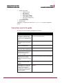
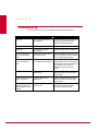
Conventions used in this guide
This document uses the following typographical conventions:
Convention
Example
Terms that identify fields, buttons,
tabs, options, selections, and
commands on the User Interface
(UI) are shown in Arial Narrow bold
font.
The Service field on the Properties tab specifies the
name of the requested service.
Menu or action group selections
are indicated using a right angle
bracket.
Select My Company > Admin Domain > View Details.
Procedures are presented as a
series of numbered steps.
1. On the Configuration tab, click Backup.
Names of keys on the keyboard
are denoted using UPPER CASE.
Press ENTER.
Text such as syntax, keywords,
and values that you must type
exactly are denoted using
Courier New font.
Type: setup and then press ENTER.
Variable information that you must Type: sensor-IP-address and then press ENTER.
type based on your specific
situation or environment is shown
in italics.
Parameters that you must supply
are shown enclosed in angle
brackets.
set sensor ip <A.B.C.D>
Information that you must read
before beginning a procedure or
that alerts you to negative
consequences of certain actions,
such as loss of data is denoted
using this notation.
Caution:
vii
McAfee® IntruShield® IPS 4.1
Preface
M-6050 Sensor Product Guide
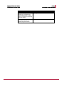
Conventions used in this guide
Convention
Example
Information that you must read to
prevent injury, accidents from
contact with electricity, or other
serious consequences is denoted
using this notation.
Warning:
Notes that provide related, but
non-critical, information are
denoted using this notation.
Note:
viii
CHAPTER 1
Overview
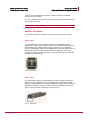
This chapter provides an introduction to IntruShield sensors.
About IntruShield sensors
IntruShield sensors are high-performance, scalable, and flexible content processing
appliances built for the accurate detection and prevention of intrusions, misuse, and
distributed denial of service (DDoS) attacks.
IntruShield sensors are specifically designed to handle traffic at wire speed, efficiently
inspect and detect intrusions with a high degree of accuracy, and flexible enough to
adapt to the security needs of any enterprise environment. When deployed at key
network access points, an IntruShield sensor provides real-time traffic monitoring to
detect malicious activity and respond to the malicious activity as configured by the
administrator.
Once deployed and once communication is established, sensors are configured and
managed using the central IntruShield ISM server.
The process of configuring a sensor and establishing communication with the ISM is
described in later chapters of this guide. The IntruShield ISM server is described in
detail in the Getting Started Guide.
Sensor functionality
The primary function of an IntruShield sensor is to analyze traffic on selected network
segments and to respond when an attack is detected. The sensor examines the
header and data portion of every network packet, looking for patterns and behavior in
the network traffic that indicate malicious activity. The sensor examines packets
according to user-configured policies, or rule sets, which determine what attacks to
watch for, and how to respond with countermeasures if an attack is detected.
If an attack is detected, a sensor responds according to its configured policy. Sensors
can perform many types of attack responses, including generating alerts and packet
logs, resetting TCP connections, “scrubbing” malicious packets, and even blocking
attack packets entirely before they reach the intended target.
Network topology considerations
Deployment of an IntruShield IPS requires knowledge of your network to help
determine the level of configuration and amount of installed sensors and ISMs
required to protect your system.
1
McAfee® IntruShield® IPS 4.1
Overview
M-6050 Sensor Product Guide
M-6050 key features
The IntruShield sensor is purpose-built for the monitoring of traffic across one or more
network segments. For more information on IntruShield, see the Getting Started Guide.
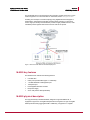
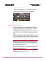
Following is an example of a network topology using Gigabit Ethernet throughput. In
the illustration, IntruShield provides IPS and Alert Viewer protection to outsourced
servers. High port-density and virtualization provides a highly scalable solution, while
IntruShield protects against Web and eCommerce mail server exploits.
Figure 1: Service Provider Data Center-based Deployment
M-6050 key features
The M-6050 sensor includes the following features:
•
•
•
•
•
•
•
8 10-GbE XFP
8 SFP ports (10/100/1000 copper or 1 GbE fiber)
1 10/100/1000 Base-T Management port
1 Response port
Hot-swappable SFP/XFP modules
Dual power supply
3 Fan units (that are field replaceable)
M-6050 physical description
The high-port density IntruShield M-6050, designed for high bandwidth links, is
equipped to support four 10 Gigabit full-duplex Ethernet segments or eight 10 Gigabit
SPAN ports transmitting aggregated traffic. Additionally, it supports four 1 Gigabit
2
McAfee® IntruShield® IPS 4.1
Overview
M-6050 Sensor Product Guide
M-6050 physical description
dull-duplex Ethernet segments or eight 1 Gigabit SPAN ports transmitting aggregated
traffic.
Ports
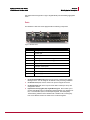
The M-6050 is a 2RU unit and is equipped with the following components:
Figure 2: M-6050 sensor
Name
Description
1
Management port
2
Console port
3
Auxiliary port
4
SFP Gigabit Ethernet Monitoring ports
5
XFP Gigabit Ethernet Monitoring ports
6
Response port
7
Fail-Open Control ports
8
External Compact Flash port
9
Power Supply A
10
Power Supply B
1
One RJ-45 10/100/1000 Management port, which is used for communication with the
Manager server. You can assign an IP address to this port during installation.
2
One RS-232C Console port, which is used to set up and configure the sensor.
3
One RS-232C Auxiliary port, which may be used to dial in remotely to set up and
configure the sensor.
4
Eight small form-factor pluggable (SFP) 1 Gigabit Monitoring ports, which enable you to
monitor eight SPAN ports, four full-duplex tapped segments, four segments inline, or a combination (that is, two full-duplex segment, four SPAN ports).
The Monitoring interfaces of the M-6050 work in stealth mode, meaning they
have no IP address and are not visible on the monitored segment.
3
McAfee® IntruShield® IPS 4.1
Overview
M-6050 Sensor Product Guide
M-6050 physical description
5
Eight 10 Gigabit small form-factor pluggable (XFP) 10 Gigabit Monitoring ports, which enable
you to monitor eight SPAN ports, four full-duplex tapped segments, four
segments in-line, or a combination (that is, two full-duplex segment, four SPAN
ports).
The Monitoring interfaces of the M-6050 work in stealth mode, meaning they
have no IP address and are not visible on the monitored segment.
If you choose to run in failover mode, port 4A is used to interconnect with a
standby sensor.
Note: The gigabit ports of the M-6050 running in In-line Mode fail closed,
meaning that if the sensor fails, it will interrupt/block data flow. Fail-open
functionality requires either the Layer 2 Passthru feature, described in detail in
the Sensor Configuration Guide—using ISM or the hardware Gigabit Fail-Open
Bypass kit for Gigabit ports, described in Cabling the failover interconnection
ports section.
6
One RJ-45 Response port, which, when you’re operating in SPAN or TAP mode,
enables you to inject response packets back through a switch or router.
7
Eight RJ-11 Fail-Open Control ports, designed for use with the Optical Fail-Open
Bypass kit. The ports are marked X1, X2, X3, X4, X5, X6, X7, and X8 and are
used in conjunction with ports 1A/1B, 2A/2B, 3A/3B, 4A/4B, 5A/5B, 6A/6B,
7A/7B, and 8A/8B, respectively.
8
One External Compact Flash port. This port is used for two purposes. It is used to
control optional fail-open hardware as described in the Gigabit Optical Fail-Open
Bypass Kit Quick Guide. It is also used in troubleshooting situations where the
sensor’s internal flash is corrupted and you must reboot the sensor using the
external compact flash. For more information, see the on-line KnowledgeBase at
https://mysupport.mcafee.com.
9
Power Supply A (included). Power supply A is included with each sensor. The
supply uses a standard IEC port (IEC320-C13). The supply uses a standard IEC
port (IEC320-C13). McAfee provides a standard, 2m NEMA 5-15P (US) power
cable (3 wire). International customers must procure a country-appropriate power
cable.
10 Power Supply B (optional, purchased separately). Power supply B is a hotswappable, redundant power supply. This power supply also uses a standard
IEC320-C13 port, and you can use the McAfee-provided cable or acquire one
that meets your specific needs.
The M-6050 does not have internal taps; it must be used with a third-party external
tap to run in tapped mode.
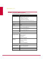
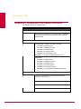
Front panel LEDs
The front panel LEDs provide status information for the health of the sensor and the
activity on its ports. Table 1-1 describes the M-6050 front panel LEDs.
4
McAfee® IntruShield® IPS 4.1
Overview
M-6050 Sensor Product Guide
M-6050 physical description
LED
Status
Description
Pwr A (Power A)
•
OK
•
•
~AC
Green
Power Supply A is functioning.
Amber
Power Supply A is not functioning.
Green
Power Supply in AC mode.
Green
Power Supply B is functioning.
Amber
Power Supply B is not functioning.
Green
Power Supply in AC mode.
Pwr B (Power B)
•
OK
•
•
~AC
Note: If a power supply is not present, both green and amber LEDs are off.
Management Port Speed
Management Port Link
Sys
Fan
Temp
Green
The port speed is 1000 Mbps.
Amber
The port speed is 100 Mbps.
Off
The port speed is 10 Mbps.
Green
The link is connected.
Off
The link is disconnected.
Green
Sensor is operating.
Amber
Sensor is booting. (It could also indicate a
system failure.)
Green
All three fans are operating.
Amber
One or more of the fans has failed.
Green
Inlet air temperature measured inside chassis
is normal. (Chassis temperature OK.)
Amber
Flash
Gigabit Ports Act
Gigabit Ports Link
Response Port Speed
Response Port Link
Inlet air temperature measured inside chassis
is too hot. (Chassis temperature too hot.)
Green
Activity on external compact flash. (For
example, the Fail-Open Controller has been
inserted.)
Off
No activity on external compact flash.
Amber
Data transferring.
Off
No data transferring.
Green
The link is connected.
Off
The link is disconnected.
Green
The port speed is 1000 Mbps.
Amber
The port speed is 100 Mbps.
Off
The port speed is 10 Mbps.
Green
The link is connected.
Off
The link is disconnected.
5
McAfee® IntruShield® IPS 4.1
Overview
M-6050 Sensor Product Guide
M-6050 physical description
LED
Status
Description
Fail-Open Control Port
Speed
Green
The link is enabled.
Off
The link is disabled.
Fail-Open Control Port
Link
Amber
There is an error.
Off
There is no error.
6
CHAPTER 2
Before You Install
Usage Restrictions
The following restrictions apply to the use and operation of an IntruShield sensor:
•
•
•
•
You may not remove the outer shell of the sensor. Doing so will invalidate your
warranty.
The sensor appliance is not a general purpose workstation.
McAfee prohibits the use of the sensor appliance for anything other than
operating the IntruShield IPS.
McAfee prohibits the modification or installation of any hardware or software in
the sensor appliance that is not part of the normal operation of the IntruShield
IPS.
Safety measures
Please read the following warnings before you install the product. These safety
measures apply to all sensor models unless otherwise noted.
Failure to observe these safety warnings could result in serious physical injury.
Warnings:
•
•
•
•
•
•
•
Read the installation instructions before you connect the system to its power
source.
To remove all power from the M-6050 sensor, unplug all power cords, including
the redundant power cord.
Only trained and qualified personnel should be allowed to install, replace, or
service this equipment.
Before working on equipment that is connected to power lines, remove jewelry
(including rings, necklaces, and watches). Metal objects will heat up when
connected to power and ground and can cause serious burns or weld the metal
object to the terminals.
This equipment is intended to be grounded. Ensure that the host is connected to
earth ground during normal use.
Do not remove the outer shell of the sensor. Doing so will invalidate your
warranty.
Do not operate the system unless all cards, faceplates, front covers, and rear
covers are in place. Blank faceplates and cover panels prevent exposure to
hazardous voltages and currents inside the chassis, contain electromagnetic
interference (EMI) that might disrupt other equipment, and direct the flow of
cooling air through the chassis.
7
McAfee® IntruShield® IPS 4.1
Before You Install
M-6050 Sensor Product Guide
Working with Fiber-Optic ports
•
To avoid electric shock, do not connect safety extra-low voltage (SELV) circuits
to telephone-network voltage (TNV) circuits. LAN ports contain SELV circuits,
and WAN ports contain TNV circuits. Some LAN and WAN ports both use RJ-45
connectors. Use caution when connecting cables.
•
This equipment has been tested and found to comply with the limits for a Class A
digital device, pursuant to Part 15 of the FCC Rules. These limits are designed to
provide reasonable protection against harmful interference when the equipment
is operated in a commercial environment. This equipment generates, uses, and
can radiate radio frequency energy and, if not installed and used in accordance
with the instruction manual, may cause harmful interference to radio
communications. Operation of this equipment in a residential area is likely to
cause harmful interference in which case the user will be required to correct the
interference at his own expense.
Refer to Appendix B for information on regulatory, compliance, and other safety
requirements.
Working with Fiber-Optic ports
The IntruShield M-6050 sensor uses fiber-optic connectors for its 16 Monitoring ports.
The connector type is a Small Form-factor Pluggable (SFP) fiber optic connector that
is LC-Duplex compatible.
•
•
Fiber-optic ports (for example, SFP/XFP, FDDI, OC-3, OC-12, OC-48, ATM,
GBIC, and 100BaseFX) are considered Class 1 laser or Class 1 LED ports.
These products have been tested and found to comply with Class 1 limits of IEC
60825-1, IEC 60825-2, EN 60825-1, EN 60825-2, and 21CFR1040.
Warning: To avoid exposure to radiation, do not stare into the aperture of a fiberoptic port. Invisible radiation might be emitted from the aperture of the port when no
fiber cable is connected.
•
Only FDA registered, EN 60825-1 and IEC 60825-1 certified Class 1 SFP laser
transceivers are acceptable for use with the M-6050 sensor.
Contents of the box
The following accessories are shipped in the M-6050 sensor box:
•
•
•
•
•
•
•
•
•
One sensor.
One power supply.
Two CD ROMS containing the sensor software and on-line documentation.
Power cords. McAfee provides a standard and international power cables.
One set of rack mounting rails.
One set of rack mounting ears.
One printed slide rail assembly procedure.
One printed quick start guide.
Release notes.
8
McAfee® IntruShield® IPS 4.1
Before You Install
M-6050 Sensor Product Guide
Unpacking the sensor
Unpacking the sensor
To unpack the sensor:
1
Place the sensor box as close to the installation site as possible.
2
Position the box with the text upright.
3
Open the top flaps of the box.
4
Remove the accessory box.
5
Verify you have received all parts. These parts are listed on the packing list and
in Contents of the sensor box.
6
Pull out the packing material surrounding the sensor.
7
Remove the sensor from the anti-static bag.
8
Save the box and packing materials for later use in case you need to move or
ship the sensor.
9
CHAPTER 3
Setting up an M-6050
This chapter describes the process of setting up a sensor to prepare it for
configuration.
Setup Overview
Setting up a sensor involves the following steps:
1
Positioning the sensor. (See below.)
2
Installing interface modules (SFP and XFP).
3
Attaching power, network, and monitoring cables. (See Attaching Cables to the
M-6050 sensor.)
4 Powering on the sensor. (See Powering on the sensor.)
Once you have set up and powered on the sensor, you can proceed with
configuration.
Positioning the sensor
Place the sensor in a physically secure location, close to the switches or routers it will
be monitoring. Ideally, the sensor should be located within a standard
communications rack.
The M-6050 is a 2RU (2 rack unit).
To mount the sensor in a rack, you will attach two mounting ears and rails to the
sensor as described below.
Installing the rails and ears on the chassis and rack
Caution: Before you install the rails and ears on the chassis, make sure that power
is OFF. Remove the power cable and all network interface cables from the sensor.
Each rack-mounting rail and ear has holes that match up with holes in the chassis.
To install the rails and ears on the chassis, follow these steps—using a Phillips
screwdriver to secure the Phillips flathead screws:
1
Verify that you have all the parts you will need: two three-in-one rails, two
chassis ears, and fourteen Phillips flathead screws. Each rail includes a rail that
mount to the rack, a rail that slides into the mounted rail, and a rail that is
attached to the chassis.
10
McAfee® IntruShield® IPS 4.1
Setting up an M-6050
M-6050 Sensor Product Guide
Positioning the sensor
2
Disassemble the slide rail by pulling the inner rail out and pushing the side latch
in to separate.
3
Attach the inner rail to the chassis by fastening it with the screws provided.
4
Attach the ear to each side of the chassis.
Mount L-shape and external rail to your rack frame. The adjustable end of the Lshape rail is intended for placement at the back of your rack. Adjust the rail as
needed for length.
You are now ready to mount the sensor in the rack.
5
Mounting a sensor in a rack
McAfee recommends rack-mounting your sensors. The rack-mounting hardware
included with the sensors is suitable for most 19-inch equipment racks and telco-type
racks. For maintenance purposes, you should have access to the front and rear of the
sensor.
Caution: Before you mount the sensor in the rack, make sure that power is OFF.
Remove the power cable and all network interface cables from the sensor
Note: Because of the weight of the appliance, McAfee recommends that two people
place the chassis into the rail cabinet.
Insert the chassis into the rail cabinet and complete the rack-mounting of the sensor
by securing the rack mount ears to two posts or mounting strips in the rack. The ears
secure the sensor to two rack posts. Ensure to fasten the ears securely to the rack.
You can also mid-mount the Sensor (optional). For details, refer to M-6050 Quick Start
Guide.
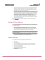
Removing a sensor from the rack
Note: Because of the weight of the appliance, McAfee recommends that two people
remove the chassis from the rail cabinet.
When removing the chassis from the rack, pull chassis forward until you hear the
innermost rails snap in place. On each side of the rails, press in the release button as
pictured below and continue pulling the chassis.
Figure 3: Rail release latch
11
McAfee® IntruShield® IPS 4.1
Setting up an M-6050
M-6050 Sensor Product Guide
Using the redundant power supply
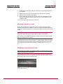
Using the redundant power supply
A basic configuration of the M-6050 includes one hot swappable supply. You may
install a second hot-swappable power supply (purchased separately from McAfee) for
redundancy.
Each of these modules has one handle for insertion or extraction from the unit as well
as a release latch.
Figure 4: Power supply units
Installing the power supply
To install a power supply in the M-6050:
1
Unpack the power supply from its shipping carton.
2
Remove the faceplate panel covering the power supply slot.
Note: The faceplate panel should remain in place unless a power supply is in
the power supply slot.
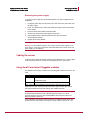
3
Do not operate the sensor without the faceplate panel in place.
4
Place the power supply in the slot with the cable outlet facing front and on the
left side of the faceplate.
Figure 5: Power supply installation
5
Slide in the power supply until it makes contact with the backplane, then push
firmly to mate the connectors solidly with the backplane.
Note: For true redundant operation with the optional redundant power supply,
McAfee recommends that you plug each supply into a different power circuit. For
optimal protection, use uninterruptable power sources.
12
McAfee® IntruShield® IPS 4.1
Setting up an M-6050
M-6050 Sensor Product Guide
Cabling the sensor
Removing the power supply
To remove a power supply from the M-6050 (Optional—the power supplies are hotswappable):
1
Unplug the power cable from its power source and remove the power cable from
the power supply.
2
Put on an antistatic wrist or ankle strap. Attach the strap to a bare metal surface
of the chassis.
3
Push the release latch inward toward the handle.
4
Squeeze the handle of the power supply and pull it out.
5
Use faceplate panels to protect unused slots from dust and reduce
electromagnetic radiation.
6
Replace the mounting bracket.
Warning 1: To remove all power from the M-6050 sensor, unplug all power cords.
Warning 2: To avoid data interruption, do not power off both power supplies on an
in-line sensor, or the sensor shuts down and all data traffic stops. Power off only the
power supply you are replacing.
Cabling the sensor
Follow the steps outlined in Attaching Cables to the M-6050 Sensor to connect cables
to the monitoring, response, console, and management ports on your sensor.
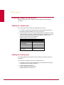
Using Small Form-factor Pluggable modules
The M-6050 uses two types of Small Form-factor Pluggable modules as shown in the
table.
Type
SPF
Performance
10/100/1000 Mbps (copper)
1 Gbps (fiber optic)
XFP
10 Gbps (fiber optic)
Each module is a hot-swappable input/output device that plugs into an LC-type
Gigabit Ethernet port, linking the module port with a copper or fiber-optic network.
SFP optical interfaces are less than half the size of GBIC interfaces.
Note: To ensure compatibility, McAfee supports only those SFP and XFP modules
purchased through McAfee or from a McAfee-approved vendor. For a list of
approved vendors, see the on-line KnowledgeBase, https://support.mcafee.com.
https://mysupport.mcafee.com
These installation instructions provide information for installing an SFP and an XFP
module that uses a bail clasp for securing the module in place in the sensor. Your
13
McAfee® IntruShield® IPS 4.1
Setting up an M-6050
M-6050 Sensor Product Guide
Using Small Form-factor Pluggable modules
module may be slightly different. Check the module manufacturer’s installation
instructions for more details.
For ease of installation, insert the module in the sensor while it is powered down and
before placing it in a rack.
Caution: To prevent eye damage, do not stare into open laser apertures.
Modules Description
This section describes the operating requirements of the SFP and XFP modules.
SFP module
The SFP (Small Form Factor Pluggable) module is a hot-swappable, protocolindependant, compact, optical receiver, which allows for greater port density than the
standard GBIC. This module operates at varying speeds for up to 1 Gigabit per
second on SONET/SDH, Fibre Channel, Gigabit Ethernet and other applications. The
SFP module operates in single mode and multimode. Additionally, this module
transmits on a 850-nanometer wavelength on short reach (SR) and 1310-nanometer
wavelength on long reach (LR).
Figure 6: SFP Module
XFP module
The supported XFP module is a robust Small Form Factor Pluggable, operating at
850nm, for up to 10 Gigabits per second on SONET/SDH, Fibre Channel, Gigabit
Ethernet and other applications. This module operates in single mode and multimode.
Additionally, this module transmits on a 850-nanometer wavelength on short reach
(SR), and 1310-nanometer wavelength on long reach (LR).
Figure 7: XFP Module
14
McAfee® IntruShield® IPS 4.1
Setting up an M-6050
M-6050 Sensor Product Guide
Power-on the sensor
Installing a module
To install a module with a bail clasp, follow these steps:
1
Remove the module from its protective packaging.
2
Ensure the module is the correct model for your network.
3
Locate the label on the module and ensure that the alignment groove is down.
Note: For SFP modules, turn the module so that its label is on top. For XFP
modules, turn the module so that its label is on bottom.
4
Grip the sides of the module with your thumb and forefinger and insert module
into the module socket.
Modules are keyed to prevent incorrect insertion.
Figure 8: Module in Monitoring port
Removing a module
If you are removing a module, follow these steps:
1
Disconnect the network fiber-optic cable from the module.
2
Release the module from the slot by pulling the bail clasp out of its locked
position.
3
Slide the module out of the slot.
4
Insert the module plug into the module optical bore for protection.
Power-on the sensor
Warning: Do not attempt to power on the sensor until you have installed the sensor
in a rack, made all necessary network connections, and connected the power cable
to the power supply.
Connect the power cable to the sensor power supply.
Connect the power cable to a power source.
15
McAfee® IntruShield® IPS 4.1
Setting up an M-6050
M-6050 Sensor Product Guide
Powering off the sensor
Note: If you are installing a redundant power supply, you should install it as
described in Installing a power supply. For true redundant operation with the
optional redundant power supply, McAfee recommends that you plug each supply
into a different power circuit.
The M-6050 sensor has no power switch. The sensor powers on as soon as one of its
power cables is connected to a power source.
Powering off the sensor
McAfee recommends that you use the shutdown CLI command to halt the sensor
before powering it down. For more information on CLI commands, see Sensor
Configuration Guide—using CLI.
16
CHAPTER 4
Attaching Cables to the M-6050
Follow the steps outlined in this chapter to connect cables to the various ports on
your sensor.
Cabling the Console port
The Console port is used for setup and configuration of the sensor.
1
For console connections, plug the DB9 Console cable supplied by McAfee into
the Console port (labeled Console on the sensor front panel).
2
Connect the other end of the Console port cable directly to a COM port of the PC
or terminal server you will use to configure the sensor (for example, a PC running
correctly configured Windows HyperTerminal software). You must connect
directly to the console for initial configuration.
Required settings for HyperTerminal are:
Name
3
Setting
Baud rate
38400
Number of bits
8
Parity
None
Stop bits
1
Flow Control
None
Power on the sensor.
Cabling the Auxiliary port
The Auxiliary (Aux) port is also used for modem access to the sensor for setup and
configuration.
You cannot use a modem the first time you configure a sensor.
1
For modem connections, plug a straight-through modem cable into the Auxiliary
port (labeled Aux on the sensor front panel).
2
Connect a modem to the Aux port.
Connect a telephone line to the modem.
Required settings for the Aux port are:
17
McAfee® IntruShield® IPS 4.1
Attaching Cables to the M-6050
M-6050 Sensor Product Guide
Cabling the Response port
Name
Setting
Baud rate
38400
Number of bits
8
Parity
None
Stop bits
1
Flow Control
None
Cabling the Response port
The sensors’ Response ports are used to send responses to attacks; when operating
in TAP or SPAN mode, for example, you cannot inject response packets via a tap.
You must use a Response port.
►
To connect the Response port to a network device:
1
Plug a Cat-5e Ethernet cable into the Response port (labeled Rx on the sensor
front panel).
2
Connect the other end of the cable to the network device (for example, hub,
switch, router) through which you want to respond to attacks.
Cabling the Fail-Open port
Fail-open functionality for the GE Monitoring ports is accomplished using the standard
Gigabit Fail-open Bypass Kit, sold separately. (Both Copper and Optical versions are
available.)
Fail-open functionality for the 10 Gigabit Monitoring ports is accomplished using the
standard 10 Gigabit (Optical) Fail-open Bypass Kit, sold separately.
For more information, see the documentation that accompanies the Kit.
Cabling the Management port
The Management (Mgmt) port is used for communication with the Manager server.
►
To connect the sensor to the Manager server:
1
Plug a Cat-5e Ethernet cable into the Management port (labeled Mgmt on the
sensor front panel).
18
McAfee® IntruShield® IPS 4.1
Attaching Cables to the M-6050
M-6050 Sensor Product Guide
Cabling the Monitoring port
2
Connect the other end of the cable to the network device (for example, hub,
switch, router) that in turn connects to the Manager server.
Note: To isolate and protect your management traffic, McAfee strongly
recommends using a separate, dedicated management subnet to interconnect the
sensors and the Manager.
Cabling the Monitoring port
Connect to the network devices you will be monitoring via the sensor Monitoring
ports. You can deploy sensors in the operating modes shown in the following table.
Cabling instructions for the sensor Monitoring ports are shown on the pages
indicated.
To cable the M-6050 in this mode...
See...
In-line mode (fail-closed)
Cabling for in-line mode
In-line mode (fail-open)
Using fail-open hardware
External tap mode
Cabling for TAP mode
SPAN or Hub mode
Cabling for SPAN or hub mode
Failover
Cabling the Failover interconnection ports
Using peer ports
All full-duplex sensor deployment modes require the use of two peer monitoring ports
on the sensor. On the sensors, the numbered ports are wired in pairs to
accommodate the traffic.
The following XFP 10 Gigabit Ethernet ports and SFP Gigabit Ethernet ports are
coupled and must be used together:
Port Pairs (and Transceiver Type)
1A and 1B (XFP)
2A and 2B (XFP)
3A and 3B (XFP)
4A and 4B (XFP)
5A and 5B (SFP)
6A and 6B (SFP)
7A and 7B (SFP)
8A and 8B (SFP)
19
McAfee® IntruShield® IPS 4.1
Attaching Cables to the M-6050
M-6050 Sensor Product Guide
Cabling for in-line
Note: You cannot configure, for example, IA and 2A to work together as a pair.
Figure 9: Port pair
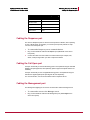
Default monitoring port speed settings
Be sure that the switch/router ports connected to the sensor Monitoring ports match
the sensor configuration.
Default monitoring port speed settings
Monitoring Ports
XFP ports
Operating Mode
Speed/Duplex Setting
SPAN
Auto-negotiation is ON
Tap
Auto-negotiation is ON
In-line
Auto-negotiation is ON
SFP ports
Cable types for routers, switches, hubs, and PCs
The cabling instructions in this chapter
•
•
•
Use a crossover Ethernet RJ-45 cable to connect a router port to the
10/100/1000 copper SFP Monitoring ports.
Use a straight-through Ethernet RJ-45 cable to connect a switch/hub port to
10/100/1000 copper SFP Monitoring ports.
Use a crossover Ethernet RJ-45 cable to connect a router port to PC to the
sensor Management port.
Note: You should also use a crossover Ethernet RJ-45 cable to connect a PC to the
sensor monitoring port.
Cabling for in-line
The Gigabit Ethernet ports fail closed, meaning they stop the flow of traffic if the
sensor fails. To allow traffic to flow uninterrupted, you must use special hardware and
cable the sensor for fail-open functionality. For instructions, see the section later in
this chapter.
To connect the M-6050’s Gigabit Ethernet ports so they fail closed:
20
McAfee® IntruShield® IPS 4.1
Attaching Cables to the M-6050
M-6050 Sensor Product Guide
Cabling for TAP mode
1
Plug the cable appropriate for use with your Gigabit Ethernet into one of the ports
labeled xA (for example, 1A).
2
Plug another cable into the peer of the port used in Step 1. This port will be
labeled xB (for example, 1B).
3
Connect the other end of each cable to the network devices that you want to
monitor. (For example, if you plan to monitor traffic between a switch and a
router, connect the cable connected to 1A to the switch and the one connected to
1B to the router.)
Cabling for TAP mode
The M-6050 sensor’s Gigabit Ethernet ports must be used with a 3rd party external
tap.
Note: For a list of approved 3rd party vendors, see the KnowledgeBase at
https://mysupport.mcafee.com
External tap mode requires a port pair (for example, 1A and 1B).
To connect the sensor to the devices you want to monitor in external tap mode:
1
Plug the cable appropriate for use with your Gigabit Ethernet port into one of the
ports labeled xA (for example, 1A).
2
Plug another cable into the other port labeled xB (for example, 1B).
3
Connect the other end of each cable to the tap.
4
Connect the network devices that you want to monitor to the tap.
Cabling for SPAN or hub mode
For the M-6050 sensor, monitoring in SPAN or hub mode occurs in in-line fail-open
mode. When you monitor in SPAN or hub mode, you do not need to use a port pair.
You can use single ports. To connect an M-6050 to a SPAN port or hub, plug an LC
fiber-optic cable into one of the modules and connect the other end of the cable to the
SPAN port or the hub.
Note: See Cable types for routers, switches, hubs, and PCs to determine which
cable type to use with which type of network device.
Cabling the Failover interconnection ports
Failover requires connecting two identical M-6050 sensors (same model, same
software) using an interconnection cable or cables.
Gigabit ports 4A is the interconnection port on the M-6050. A failover cable is the
only additional hardware required to support failover communication between two M6050 sensors.
21
McAfee® IntruShield® IPS 4.1
Attaching Cables to the M-6050
M-6050 Sensor Product Guide
Using Fail-Open hardware
To connect two M-6050s for failover:
1
Plug the cable appropriate for use with your XFP module into port 4A of the
active sensor.
2
Connect the other end of the cable to port 4A of the standby sensor.
Figure 10: Cabling M-6050 sensors for Failover
Using Fail-Open hardware
The standard Gigabit Fail-Open Kit and the 10 Gigabit Fail-Open Kit (sold separately)
minimizes the potential risks of in-line IntruShield sensor failure on critical network
links. Both Copper and Optical versions of the Kit are available for 1 Gigabit ports. A
10 Gigabit Optical Kit is also available for the 10 Gigabit ports.
The Monitoring ports on IntruShield sensors fail closed; thus, if the sensor is deployed
in-line, a hardware failure results in network downtime. Fail-open operation for the
Monitoring ports requires the use of the optional external Bypass Switch provided in
the Kit.
With the Bypass Switch in place, normal sensor operation supplies power to the
switch via a control cable. While the sensor is operating, the switch is “on” and routes
all traffic directly through the sensor. When the sensor fails, the switch automatically
shifts to a bypass state: in-line traffic continues to flow through the network link, but is
no longer routed through the sensor. Once the sensor resumes normal operation, the
switch returns to the “on” state, once again enabling in-line monitoring.
Caution 1: Note that sensor outage breaks the link connecting the devices on
either side of the sensor for a brief moment and requires the renegotiation of the
network link between the two peer devices connected to the sensor. Depending on
the network equipment, this disruption introduced by the renegotiation of the link
layer between the two peer devices may range from a couple of seconds to more
than a minute with certain vendors’ devices.
Caution 2: A very brief link disruption may also occur while the links between the
sensor and each of the peer devices are renegotiated to place the sensor back in
in-line mode. This outage, again, varies depending on the device, and can range
from a few seconds to more than a minute.
Installation and troubleshooting instructions for the Kit can be found in the Quick
Guide that accompanies the kit. For example, for more information on the Optical kit,
see the standard Gigabit Optical Fail-Open Bypass Kit Guide.
22
CHAPTER 5
Troubleshooting
This section lists some common installation problems and their solutions.
Problem
Possible Cause
Solution
LED is off.
The control cable has been
disconnected.
Check the control cable and ensure it
is properly connected to both the
sensor and the Bypass Switch.
LED is off.
The sensor is powered off.
Restore sensor power.
LED is off.
The sensor port cable is
disconnected.
Check the sensor cable connections.
Sensor is operational,
but is not monitoring
traffic.
Network device cables have
been disconnected.
Check the cables and ensure they are
properly connected to both the network
devices and the Bypass Switch.
Sensor is operational,
but is not monitoring
traffic.
The sensor ports have not
The sensor will not monitor traffic on
been enabled in the Manager. the ports unless the ports are enabled
in the Manager. Ports are disabled in a
sensor failure; they must be reenabled for sensor monitoring to
resume.
Network or link problems. Improper cabling or port
configuration.
Ensure that the transmit and receive
cables are properly connected to the
Bypass Switch.
Runts or giants errors on
switch and routers.
Improper cabling or port
configuration.
Ensure that the transmit and receive
cables are properly connected to the
Bypass Switch.
The system fault “Switch
absent” appears in the
Manager System Health
window.
The control cable has been
disconnected.
Check the control cable and ensure it
is properly connected to both the
sensor and the Bypass Switch.
23
APPENDIX A
Sensor Technical Specifications
The following table lists the specifications of the M-6050 sensor.
Sensor Specifics
Dimensions
Description
Without mounting ears/rails/cable management:
•
•
•
Width: 16.75 in. (41.91 cm)
Height: 3.5 in. (8.89 cm)
Depth: 30.00 in. (76.20 cm)
Dimensions do not include cables or power cords.
Weight
47 lbs (21.31 kg)
Voltage Range
100-240VAC
Frequency
50/60Hz
Vibration, operating
Sinusoidal: 3 to 500 Hz @ 0.15 gpk
Random: 2.5 to 200 Hz @ 0.33 g
Vibration, non-operating
Sinusoidal: 10 to 500 Hz @ 0.8 gpk
Random: 2.5 to 200 Hz @ 1.05 g
Power requirements
450W
Temperature
Ambient Temperature
Range (Non-condensing)
Operating
0C(32F) to 35C(95F)
Non-operating
-40C(-40F) to 70C(158F)
Relative Humidity (Noncondensing)
Operating
5%-90% non-condensing
Non-operating
5% to 95% non-condensing
Sensor Specifics
System Heat Dissipation
AC (max): 535W, 1825 BTU/hr
DC (max): To Be determined
Airflow
200 lfm (1 m/s)
Altitude
Sealevel to 10,000 ft (3050m)
24
APPENDIX B
Regulatory, Compliance, and Safety Information
The M-6050 meets the following standards:
Sensor Regulatory, Safety, and Compliance
Regulatory
Products with the CE Marking are compliant with the 89/336/EEC
and 73/23/EEC directives, which include the safety and EMC
standards listed.
Safety certification:
EN 55024: 1998 + A1:2001 + A2: 2003 - Immunity:
•
•
•
•
•
EN-61000-4-2: ESD Immunity
EN-61000-4-3: Radiated Immunity
EN-61000-4-4 EFT/B Immunity
EN-61000-4-5: Surge Protection
EN-61000-4-6: Conducted Immunity
EN-61000-4-11: Voltage Interruption/Dips (N/A for DC)
CISPR/KN22
•
•
•
•
•
•
KN-61000-4-2: ESD Immunity
KN-61000-4-3: Radiated Immunity
KN-61000-4-4 EFT/B Immunity
KN-61000-4-5: Surge Protection
KN-61000-4-6: Conducted Immunity
KN-61000-4-11: Voltage Interruption/Dips (N/A for DC)
Electromagnetic compliance (emissions):
FCC Part 15 Class A/Industry Canada ICES-003 Issue 4,
February 7, 2004 Class A
VCCI V-1/93.11, V-2/97.04, V-4/97 Class A
AS/NZS CISPR22: 2004 Class A
CNS 13438: May 1997
25
McAfee® IntruShield® IPS 4.1
Regulatory, Compliance, and Safety Information
M-6050 Sensor Product Guide
Using Fail-Open hardware
Sensor Regulatory, Safety, and Compliance
SS IEC CISPR22: 1993, Singapore IDA Class A
EN 55024: 1998 + A1:2001 + A2: 2003 - Emissions:
•
•
•
•
Radiated Emissions
Conducted Emissions
EN 61000-3-2: 2000 Harmonic Current Emissions
EN 61000-3-3: 1995 + A1: 2001 Voltage Fluctuation/Flicker
CISPR/KN22
•
•
Radiated Emissions
Conducted Emissions
26
APPENDIX C
Sensor Capacity
The following table lists the sensor's capacity to handle data operations within the
following categories:
Operation Type
Maximum Capacity
Concurrent connections
1,000,000
Connections established per sec.
25,000
Concurrent SSL Flows (2.1.x and later)
100,000
Number of SSL keys that can be stored on the sensor
64
Virtual IDS sessions
1000
Virtual Interfaces (VIDS)
1000
VLANS / CIDR Blocks
3000
VLANS / CIDR Blocks per Physical Port
254
Customized attacks
100,000
Alert filters
128,000
Default number of supported UDP Flows
100,000
Supported UDP Flows
750,000
DoS Profiles
5000
SYN rate (64-byte packets per second)
1,000,000
ACL Rules (refer to note below)
1000
27