1
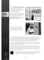
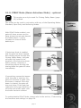
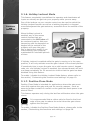
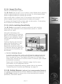
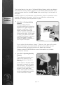
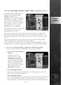
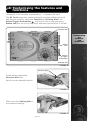
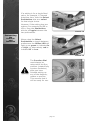
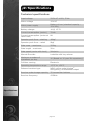
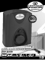
Centurion Logo
D2 Turbo domestic sliding gate operator
User guide
SLIDING GATE
OPERATORS
SWING GATE
OPERATORS
GARAGE DOOR
OPERATORS
REMOTE
CONTROLS
INTERCOMS
SAFETY BEAMS
KEYPADS
Company overview
Centurion Systems has been manufacturing automatic gate systems since 1986, and is
committed to providing reliable, cost effective solutions in the field of gate and access
automation.
We offer a diverse range of products including gate motors, GSM-based products, garage
door motors, remote controls, keypads, traffic barriers, proximity access control and
intercom systems.
Our products are developed by an in-house team of talented engineers that are constantly
researching new and innovative products to add to our range and upgrade existing models.
We are accredited with the world class quality assurance system, ISO 9001-2008, to ensure
that our products are manufactured to the highest level of quality with a 100% test to
specification.
Through a team of dedicated technicians and sales personnel, together with a fully fledged
in-house training facility, we are committed to providing unmatched service and support for
our products.
The equipment is installed worldwide and is available through a network of competent
distributors and installers.
Further information is available on our website www.centsys.co.za.
Centurion Systems (Pty) Ltd. reserves the right to make changes to the products described in this document without
notice and without obligation of Centurion Systems (Pty) Ltd. to notify any persons of any such revisions or changes.
Additionally, Centurion Systems (Pty) Ltd. makes no representations or warranties with respect to this document.
No part of this document may be copied, stored in a retrieval system or transmitted in any form or by any means
electronic, mechanical, optical or photographic, without the express prior written consent of Centurion Systems (Pty) Ltd.
Contents
IMPORTANT SAFETY FEATURES
page 1
Introduction
page 2
D2 Turbo overview
page 2
1.
Identification of parts
page 3
2.
Manual Override
page 4
2.1.
Disengage the gearbox/drive
page 4
2.2.
Re-engage the gearbox/drive
page 4
3.
Features and functions
page 5
Introduction
page 5
3.1.
Gate Operation
page 5
3.1.1.
Full Gate Opening
page 5
3.1.2.
Modes of Operation
page 5
3.1.2.1.
Standard Mode
page 5
3.1.2.2.
Open Only Mode
page 6
3.1.2.3.
Reversing Mode
page 6
3.1.3.
Automatic Closing (Autoclose Mode)
page 7
3.1.3.1.
page 7
Autoclose Override
3.1.4.
Pedestrian Opening
page 8
3.1.5.
PIRAC Mode (Beam Autoclose) - optional
page 9
3.1.6.
Holiday Lockout Mode
page 10
3.1.7.
Positive Close Mode
page 10
3.1.8.
Speed Profiles
page 11
3.1.9.
Anti-crushing Sensitivity
page 11
3.1.9.1
page 11
3.1.10.
3.1.11.
Collision Count
Safety beams (optional, but recommended feature)
page 11
3.1.10.1.
Closing Safety Beams
page 12
3.1.10.2.
Opening Safety Beams
page 12
Courtesy (Pillar) Light Timer (optional feature)
page 13
3.1.11.1.
page 13
Courtesy (Pillar) Light act as Warning Light
3.1.11.1A. Pre-flashing Modes
page 13
3.1.12.
External Gate Status Indication LED
page 14
3.1.13.
Battery Low Protection
page 14
4.
page 15
Customising the features and functions
Examples:
page 17
A. Setting up the gate Limits
page 18
B. Remote control administration
TM
C. Adding NOVA remote controls (Keeloq
5.
encryption)
page 19
D. Deleting specific remote controls
page 20
E. Deleting ALL remote controls
page 21
F. Setting the Autoclose feature
page 22
G. Setting the Mode of Operation
page 24
H. Setting PIRAC Mode
page 26
I. Setting the Pre-flashing Modes
page 27
J. Setting the Operating Profiles
page 28
K. Verifying your setup
page 30
Additional features
page 31
5.1.
Battery saver
page 31
5.2.
Solar power supply
page 31
6.
Basic Maintenance
page 32
7.
Servicing your D2 Turbo
page 32
8.
Diagnostics
page 33
9.
Specifications
page 34
10.
24 Month product warranty
page 35
11.
Optional extras
page 37
Icons used in this user guide
This icon indicates tips and
other information that could be
useful during the installation.
This icon denotes variations and
other aspects that should be
considered during installation.
This icon indicates warning, caution or attention! Please take special note of
critical aspects that MUST be adhered to in order to prevent injury.
IMPORTANT Safety instructions
Even if you have owned and used an automated gate before, we suggest that
you read through the safety instructions below very carefully. Although years
of thought have been put into every CENTURION product – and your safety is
our top priority – accidents do happen. So, please make sure that you fully
understand the following safety requirements before using your automated
gate.
Before you attempt to use your new gate operator for the first time, you
should know:
&
How to operate the Manual Release thumbwheel
&
How the Obstruction Detection System and all other safety features work
&
All the safety considerations that come with operating an automated gate
– and the importance of explaining these considerations to everyone who
uses the operator
DOs and DON’Ts
1. Do not activate your gate opener unless you can see it. Make sure that no
people, pets or any other obstructions are in your gate’s area of travel.
2. NO ONE MAY CROSS THE PATH OF A MOVING GATE. Our advanced
obstruction detection technology is designed to stop your gate in its
tracks should a child or pet be in the way. However this is a reactive
system and should never supersede proactive measures of preventing
people, pets or vehicles from moving into the path of a moving gate.
3. Check if the obstruction detection system and safety devices for correct
operation are in working order once a month.
4. Children should be supervised to ensure that they do not play with the
appliance.
5. This appliance is not intended for use by persons (including children) with
reduced physical, sensory or mental capabilities, or lack of experience
and knowledge, unless they have been given supervision or instruction
concerning use of the appliance by a person responsible for their safety.
6. Always be mindful of where your limbs are when dealing with moving
parts – you don’t want your fingers to be pinched (or worse).
7. Keep your gate controls (remote controls) in a safe place. You don’t want
anyone getting in uninvited.
8. Look after your gate and it will look after you. Ensure that all working
areas are debris-free and that your automated system is well-maintained
and your CENTURION operator should last you a very long time.
9. Ensure that any technician that works on your operator has been trained
by CENTURION.
10. This product was designed and built strictly for the use indicated in this
documentation. Any other use, not expressly indicated here, could
compromise the good condition/operation of the product and/or be a
source of danger.
11. Centurion Systems does not accept any liability caused by improper use
of the product, or for use other than that for which the automated system
was intended.
page 1
Introduction
This User Guide contains all the information you need to configure and
operate your new D2 Turbo Sliding Gate Operator.
From safety instructions to basic principles of operation and an in-depth
description of your CENTURION product’s many features and functions,
by the time you have finished reading this guide you will have learnt
how to make the most out of your gate operator.
Even Basic Maintenance is covered but, in the unlikely event that your
CENTURION product malfunctions, rather leave it to the professionals
and contact your installer or nearest Centurion Systems branch (contact
details listed on the back page) for prompt assistance.
D2 Turbo overview
The D2 Turbo has various useful features and functions, all easily
accessible from a user-friendly dial-based setup system. Multiple Modes
of Operation,Speed Profiles, an onboard multichannel receiver – you
name it, the D2 Turbo's got it.
The integral 12V 5Ah battery (charged by an internal 220V charger)
comes with full battery backup and advanced lightning protection so you
can always get in – even when the power is out. For increased power
capacity you can install a larger, 7Ah battery (your D2 Turbo was
designed to cater for this), or you can even use a solar panel to power
it. (see the section on Solar Panels, for more details about solar
charging)
The D2 Turbo is designed to open and close domestic sliding gates
weighing up to 250kg. It must not be installed or used to automate the
entrances of townhouses complexes, housing estates, commercial or
industrial properties.
The gearbox, moulded from a high-tech engineering polymer not only
looks good, but is corrosion-free and guarantees that even if you live at
the coast, your D2 Turbo will just keep on going.
For your security, the internal gearset has a self-locking action so forced
entry is not an option for would-be burglars.
An optional Theft-resistant Cage and Theft-resistant Locking Nut makes
intruders’ lives even more difficult.
For your safety, our revolutionary limit switch mechanism monitors the
speed and location of your gate for accurate position control and
sensitive anti-crushing protection.
page 2
Identification
of
parts
1. Identification of parts
Refer to the drawings below, for how to identify your D2 Turbo operator
and its parts.
1. Motor fuse
2. Motor enclosure
unit
7
1
8
3. Camlock cover
9
4. Manual release
thumbwheel
5. Foundation plate
10
11
2
6. Spare fuse
12
7. Function Dial
13
8. Status LED
9. Pushbutton
10. D2 Turbo
controller
3
14
4
11. Settings Dial
12. 12V 7.2Ah or
5Ah battery
13. Battery strap
14. Pulley guard
15
5
15. Gate mounted
origin marker
16
16. Origin marker
bracket
17
17. D2 Turbo
controller
18
18. 12V 7.2Ah or
5Ah battery
19. Motor housing
6
19
20. Pinion
21. Pinion guard
20
21
FIGURE 1
page 3
2. Manual Override
Manual
Override
2.1. Disengaging the
gearbox/drive
To manually override the
operator you will need to: Open
the camlock cover, insert the
camlock key and rotate it 90°
clockwise (the operator cover
can also be removed at this
stage if so desired).
This will allow for the rotation of
the Manual Release
thumbwheel.
By turning the Manual Release
thumbwheel 90° counterclockwise until it clicks, the
motor pinion will be put into
‘Manual Mode’.
FIGURE 2
2.2. Re-engaging
gearbox/drive
To re-engage the drive
mechanism of the operator, turn
the Manual Release thumbwheel
90° clockwise until it clicks.
Once you have re-engaged the
drive mechanism don’t forget to
lock the camlock by inserting
the key and rotating it 90?
counter-clockwise – this will
help prevent unauthorised
tampering with the operator.
By locking the camlock, the
Manual Release thumbwheel
cannot be moved from ‘locked’
to ‘unlocked’ and vice versa.
FIGURE 3
page 4
3. Features and functions
Introduction
The D2 Turbo sliding gate operator's advanced functions are controlled
by an intelligent micro-controller based electronic controller.
Features
and
functions
FIGURE 4
3.1. Gate operation
3.1.1. Full Gate Opening
The NOVA remote controls (with
KeeloqTM encryption) supplied
with the D2 Turbo are used to
operate the gate.
However, most automatic gate
installations are also fitted with
an intercom, which provides for
communication between the
house or building and the gate.
The handset is usually fitted
with a gate pushbutton, which
when pressed, sends a signal to
the D2 Turbo controller to
operate the gate.
FIGURE 5
3.1.2. Modes of Operation
To operate the gate to open fully, the D2 Turbo has three modes to
choose from depending on the application. Only one mode can be
selected at any given time.
&
3.1.2.1. Standard Mode
Standard Mode is the most commonly used mode for domestic
applications as it allows full control of the gate. Press the remote
control button for approximately one second to get the gate in
motion. If the remote control button is pressed while the gate is
page 5
moving, the gate will stop. Press the remote control button again
and the gate will go into reverse.
Autoclose (page 7) and PIRAC (Beam Autoclose) (page 9) can be
used together with Standard Mode.
Features
and
functions
&
3.1.2.2. Open Only Mode
This mode is ideal for increased safety in multi-user single dwelling
applications.
If you select Open Only Mode, your gate will open when you press
the button of the remote control or the gate pushbutton on the
intercom – but pressing the button again while the gate is opening
will be ignored. It will not cause the gate to stop or to reverse.
Only the internal Autoclose feature described on page 7 of this User
Guide, which is automatically enabled, will close the gate if you have
selected Open Only Mode.
If the button of the remote control or intercom gate release is
pressed while the gate is closing, the gate will immediately reopen.
The gate cannot be stopped in a midway position and will therefore
always close. If the button is pressed while the gate is in the open
position, the Autoclose timer (page 7) will be reset.
We highly recommended that a pair of safety beams are
installed across the gate entrance and connected to the
closing safety beam input on the D2 Turbo if you select
Open Only Mode. This will prevent the gate from closing
on people, pets or vehicles. (page 11)
PIRAC (Beam Autoclose) (page 9) can be used with Open
Only Mode.
&
3.1.2.3. Reversing Mode
Reversing Mode offers slightly more security than Standard Mode as
it allows you to close your gate quickly by pressing, for instance,
your remote control just as you drive through the gate to prevent
children or pets running out - or anybody getting in behind you.
When pressing the button of the remote control or the gate
pushbutton on the intercom, your gate will be set in motion. If you
press the button again, the gate will move in the opposite direction.
So, if the gate is opening and you press the button, the gate will
stop and immediately start to close (and vice versa).
Autoclose (page 7) and PIRAC (Beam Autoclose) (page 9)
can be used with Reversing Mode.
To configure any of the operating modes please refer to the section,
‘Customising the Functions and Settings’ on page 24.
page 6
3.1.3. Automatic closing (Autoclose Mode)
The D2 Turbo has the facility to automatically close the gate after it
has opened (Autoclose Mode). The time that the gate stays open is by
default fifteen seconds, but this time period can be set to be five, ten,
fifteen, thirty, or forty-five seconds.
As described in the previous section, Autoclose Mode is selectable with
Standard Mode (page 5) and Reversing Mode (page 6) - by default the
function is Off. However, Autoclose is automatically enabled in Open
Only Mode.
CENTURION highly recommends that if you select Autoclose
Mode in order to prevent the gate from closing on people,
pets or vehicles, a pair of safety beams are installed across
the gate entrance and connected to the Closing Safety Beam
input on the D2 Turbo.
&
3.1.3.1. Autoclose Override
Autoclose Mode can be
overridden in Standard and
Reversing Modes by pressing
and holding the button of the
remote control or intercom gate
release for no less than three
seconds. The gate response will
be to start opening and then to
stop as soon as the Autoclose
Override feature is activated.
On releasing the button, the
gate will continue opening until
fully open.
Your gate will stay open until
you use the remote control or
intercom gate release to close
the gate. The D2 Turbo will
then revert to normal Autoclose
operation.
Press and hold remote
control pushbutton;
gate will start to open
STOP
Gate stops to indicate
that Autoclose Override
has been engaged
The Autoclose
function cannot be
overridden in Only
Open Mode.
To enable/disable the Autoclose
function and/or change the
Autoclose time, please refer to
the section, 'Customising the
Functions and Settings' on page
22.
Release pushbutton;
gate will continue to open
fully and stay open
FIGURE 6
page 7
Features
and
functions
3.1.4. Pedestrian Opening
The Pedestrian Opening input
opens the gate just wide enough
for a pedestrian to pass
through the opening.
Features
and
functions
A second button on your remote
control can be used to operate
the Pedestrian Opening function.
You can also connect a
keyswitch or keypad mounted
adjacent the gate entrance to
operate this function.
FIGURE 7
There is a default two second
delay before the gate opens.
This is to warn the pedestrian
that the gate is about to move.
FIGURE 8
It will also give the person enough time to move their hand away if they
are reaching through the gate to operate a keyswitch or a keypad*. If
the Courtesy Light* (page 13) is connected to the D2 Turbo's control
card, it will flash indicating that the gate will open approximately one
metre. The gate will close after a default time of five seconds.
The gate can be kept open by keeping a trigger on the input (keeping
your key in the keyswitch, for example) – once removed the gate will
close after the fixed five seconds.
If a Closing Safety Beam (page 12) is fitted and the beam is broken
while the gate is closing, the gate will stop and open to the Pedestrian
Opening position. The gate will remain open while the beam is broken
and the five second (fixed) Autoclose Delay will only commence once
the beam has been cleared.
* For safety reasons it is recommended that all pedestrian
keyswitches and keypads are installed on the opposite end
of the gate to where the operator is installed.
page 8
3.1.5. PIRAC Mode (Beam Autoclose Mode) - optional
This mode can only be used if a Closing Safety Beam (page
12) is fitted.
This mode can be used in conjunction with any of the Operating Modes Standard, Open Only and Reversing Modes.
Gate
opening
With PIRAC Mode enabled, your
gate will close as soon as you
have driven through and passed
the Safety Beam – giving
intruders no time to follow
behind you.
Beam
FIGURE 9
If Autoclose Mode is enabled
and the gate has been opened
but nothing moves through the
Closing Safety Beam, the gate
will stay fully open for the
duration of the Autoclose timer
before closing. However, if
something passes through the
closing beam the gate will close
immediately.
Gate
opening
Beam
broken
FIGURE 10
If something crosses the beams
while the gate is opening, the
gate will continue to open until
the beam is cleared. Once the
beam is cleared, the gate will
stop and close. If the gate has
reached its fully open position, it
will stop and remain open until
the beam has been cleared.
Gate
closing
Beam
re-made
FIGURE 11
To enable/disable PIRAC Mode, please refer to the section, 'Customising
the functions and settings' on page 26.
page 9
Features
and
functions
3.1.6. Holiday Lockout Mode
This feature completely immobilises the operator and deactivates all
inputs so nobody can get into your property while you are away.
Features
and
functions
One of the buttons on your remote control can be used to switch the
Holiday Lockout function as well as a latching keyswitch or keypad
mounted adjacent the gate entrance, accessible from the outside of the
property.
When Holiday Lockout is
enabled, any of the access
control devices that are
connected to the D2 Turbo will
be rendered inactive. Not even
tampering with the keyswitch or
keypad on the outside of the
property will open the gate –
this is particularly useful if you
intend leaving your property
unattended for extended periods
of time.
FIGURE 12
If Holiday Lockout is enabled while the gate is moving or in the open
position, it will only activate once the gate is back in the closed position.
If somebody tries to open the gate via a valid remote control, keypad
code, etc. and Holiday Lockout is enabled, the onboard buzzer will emit
one beep periodically for 30 seconds to confirm that the gate has been
disabled using this feature.
To enable / disable the Holiday Lockout Mode feature, please refer to
the section, 'Customising the functions and settings' on page 19.
3.1.7. Positive Close Mode
Positive Close Mode is intended for applications where the gate must
close fully against the gate end post for security reasons – such as
ensuring proper contact of a switch on the gate that feeds power to an
electric fence.
This feature operates only during the last few millimetres when the gate
closes.
It is recommended that a rubber strip be fixed to the front
edge of the gate to reduce the noise when the gate closes
against the end post.
To enable / disable the Positive Close Mode feature, please refer to the
section, 'Customising the functions and settings' on page 28.
page 10
3.1.8. Speed Profiles
There’s no substitute for speed!
The D2 Turbo can be set to run on either a High Speed Mode (default)
which is approximately 24 metres per minute, or a Low Speed Mode
which is approximately 16 metres per minute.
High speeds offer a greater level of convenience and security, while
slower speeds ensure increased levels of safety at the gate.
To change the Speed Profile, please refer to the section, 'Customising
the Functions and Settings' on page 29.
3.1.9. Anti-crushing Sensitivity
The D2 Turbo incorporates a sensitive electronic anti-crushing
technology that responds in the events that a person or vehicle
obstructs your gate.
Using this technology, the
typical response for an opening
gate is to immediately stop and
retract a short distance, while a
closing gate will stop and fully
re-open.
Collision Sensing can be set to
either High Sensitivity or Low
Sensitivity. Generally High
Sensitivity should be used, but
in instances where the gate runs
very poorly Low Sensitivity can
be selected.
FIGURE 13
&
3.1.9.1. Collision Count
A counter monitors the number of collisions the gate experiences
before it fully closes. If the number exceeds the default value of
four, the gate will stop. The Status LED (page 14) will flash four
times every second until a remote control or intercom gate release
pushbutton is pressed.
Please refer to Gate Status Indication (page 14) for more
information on this diagnostic device.
To change the Sensitivity setting, please refer to the section,
'Customising the Functions and Settings' on page 30.
3.1.10. Safety Beams
(optional, but recommended feature)
It is always recommended to connect additional safety mechanisms to
the D2 Turbo instead of relying only on the inherent anti-crushing
protection, referred to above.
page 11
Features
and
functions
The typical device is a pair of Infrared Safety Beams which can detect
the presence of any vehicle, person or pet that breaks the beam and
communicates back to the D2 Turbo that something is in the path of
the gate.
Features
and
functions
Another option is an Inductive Loop Detector, which is mounted in the
ground, adjacent to the gate, which is very effective at detecting
vehicles or the like, but not persons or pets.
&
3.1.10.1. Closing Safety
Beams
Closing Safety Beams
provide additional protection
against your gate closing on
people or vehicles. If the
beam is broken while the
gate is opening, the gate will
continue to open. If the gate
is open, the gate cannot be
closed if the beam is broken,
and if the gate is closing
when the beam is broken, it
will stop and reopen.
FIGURE 14
If you select the Autoclose (page 7) feature, the gate will remain
open if the beam is broken and it will only close after the set
Autoclose time has expired when the beam has cleared.
Please contact CENTURION for more information on suitable
protection devices.
&
3.1.10.2. Opening Safety
Beams
These beams prevent your
gate from opening if an
object, person or pet is in
the way.
If the beam is broken while
the gate is closed, the gate
will not open. If the gate is
opening and the beams are
broken, it will stop then
close. If the gate is closing
while the beams are broken,
it will continue to close.
FIGURE 15
page 12
3.1.11. Courtesy (Pillar) Light Timer
(optional feature)
Courtesy (Pillar) Lights can be
connected through the D2
Turbo controller if an
adequate* 220V power supply is
available at the gate. The lights
will switch on every time the
gate is given a signal to operate
(the trigger could be a remote
control button, or the gate
pushbutton on an intercom.
Features
and
functions
The lights will stay on for a fixed
period of two minutes, then
automatically turn off.
FIGURE 16
The purpose is to bathe your entrance with light when you open the
gates and increase your security as you drive into your property – it
also saves electricity as the lights only come on when you use the gate
motor.
Using the Pedestrian Opening feature will cause the Courtesy (Pillar)
Lights to flash three times before the gate opens.
*The cabling that supplies the 220V supply to the D2 Turbo must be
suitably sized to carry the additional load of the courtesy (pillar) lights.
&
3.1.11.1. Courtesy (Pillar) Lights act as Warning Light
These modes replace the standard Courtesy Light feature
&
3.1.11.1A. Pre-flashing
Modes
Depending on your
requirements or local
regulations, your gate
automation system can
provide for two different
safety Pre-flashing Modes
which will activate the
gate’s pillar lights if fitted
and connected to the
D2 Turbo controller.
FIGURE 17
&
Pre-flashing Mode A
With Pre-flashing Mode A activated, the pillar light relay will only
activate during gate movement.
&
Pre-flashing Mode C
With Pre-flashing Mode C activated, the pillar light relay will activate
for two seconds before gate movement occurs, as well as during
gate movement. This means that gate movement will be delayed for
page 13
a period of two seconds after a trigger signal has been received.
To change the Courtesy (Pillar) to one of the Pre-flashing Modes, please
refer to the section, 'Customising the functions and settings' on page 27.
3.1.12. External Gate Status Indication LED
Features
and
functions
A LED (Light Emitting Diode)
mounted on your intercom
allows you to view the position
of your gate and the condition of
the battery and power supply
from the safety of your home.
The different signals of the LED
are described below:
FIGURE 18
Off
Gate is closed
On
Gate is partially or fully open
Continuous slow flash
Gate is opening
Continuous fast flash
Gate is closing
Two flashes every two seconds
No mains present
Three flashes every two seconds
Battery voltage is low
Four flashes every two seconds
Multiple collisions have occurred
If you choose not to fit a Gate Status Indicator, the Status LED
on the controller can also be used for trouble-shooting.
3.1.13. Battery Low Protection
The D2 Turbo’s controller has circuitry that monitors the state of the
battery. During a power failure, energy is drawn from the battery but
not replaced.
To protect the battery from being quickly damaged, the protection
circuitry prevents the motors from being run off the battery when the
battery voltage drops below 10.6 volts.
Indication that the Battery Low Protection has been triggered is
provided by the onboard buzzer and status LED on the controller (and
intercom if so equipped and connected to the controller). The LED will
flash three times every two seconds, as will the buzzer beep three times
every two seconds.
The gate system will also shut off until such time as the battery has
recharged to an acceptable level.
Consult your gate automation specialist or Centurion Systems if you
discover that your Battery Low Protection signal continues to re-occur.
page 14
4. Customising the features and
functions
"Simplicity is the ultimate sophistication". ~ Leonardo Da Vinci
The D2 Turbo controller makes ordinarily complex settings as quick
and easy as possible. Using the Function and Setting Dials, the
Select/Toggle Pushbutton
, and the bi-colour (red and green)
Status LED you can set up the many features and functions in a flash.
Function Dial
Customising
the
features
and
functions
Status
LED
Select/
Toggle
Pushbutton
Settings Dial
FIGURE 15
Function Dial
Please always adjust the
Function Dial first.
Set this to the desired function.
FIGURE 16
Then move the Setting Dial to
the preferred setting.
FIGURE 17
page 15
If a setting is for a single fixed
value, for example, 15 second
Autoclose time, then the Select
Pushbutton acts as a select
for that single choice.
However, if the setting has two
options, for example On/Off or
Hi/Lo, then the Pushbutton
acts as a Toggle between the
two preferences.
Customising
the
features
and
functions
FIGURE 18
When using the Select
Pushbutton to toggle between
preferences the Status LED will
light up as green to indicate On
or High; or alternatively red to
indicate Off or Low.
FIGURE 19
The Function Dial
must always be
returned to the Run
position (rotated fully
counter-clockwise)
after you have
finished setting up
any of the features,
modes or profiles.
This ensures that it
will be ready for use.
FIGURE 20
page 16
Examples:
A. Setting up the gate Limits
This is usually performed by an installer at the end of the installation.
However, should you need to change these settings, you can do this by
simply following these steps:
Step 1: Ensure the gate is in the fully closed position and the motor
drive is engaged.
Customising
the
features
and
functions
Step 2: Rotate the Function Dial
to the LIMITS position (A).
Step 3: Rotate the Setting Dial
to the SETUP position along the
‘A’ row of options.
FIGURE 21
Step 4: Press the Pushbutton to
select this feature.
FIGURE 22
The gate will then run through
its automated procedure to
determine the gate's open and
closed positions. If setup is
successful, the Status LED will
be green, which indicates the
setup has finished.
FIGURE 23
Step 5: Return the Function
Dial to the RUN position.
FIGURE 24
page 17
B. Remote control administration
Customising
the
features
and
functions
The D2 Turbo controller
incorporates an onboard
multichannel receiver compatible
with NOVA secure rolling code
(KeeloqTM encryption). The receiver
will allow any combination of the
different inputs - Trigger (Gate
fully open), Pedestrian, Holiday
Lockout, etc. to be operated from
a single multi-button remote
control.
You can also artificially increase
the number of buttons by using a
two button combination. One of
the buttons is used as a shift
button to allow the other buttons
to be used again in combination
with this button. Press and hold
the allocated shift button and
then press one of the other
buttons to create a new button.
The shift button cannot be used
as a button on its own - it must
always be used in combination
with another button.
FIGURE 25
2
Shift key
1
3
5
Shift key
4
Use of the shift button principle
allows a three button transmitter to
gain an extra button and operate
four functions and a four button
transmitter gains two extra buttons
and can operate six functions. This is
quite handy if you’d like to control
additional devices from a single
multi-button remote control, for
example your garage doors if they
are equipped with CENTURION
NOVA rolling code receivers
(KeeloqTM encryption).
6
Press and
hold the
‘fourth’ button
as a shift key
together with
button 1, 2 or
3 to operate
4, 5 or 6
FIGURE 26
However, it’s important to note that the other devices cannot be activated with
the new shift button, only the D2 Turbo (and other CENTURION operators that
are equipped with an onboard receiver) is able to recognise the shift button
signals. Using the shift key principle also prevents you from enabling functions like
Holiday Lockout Mode by accident. This is because you have to use both hands to
press the two button combination.
At any stage remote controls can be selectively added or deleted within the
system. To selectively delete a remote control, the remote control must be
available, please refer to the section, 'Deleting specific remote controls' on
page 20.
page 18
C. Adding NOVA remote controls (KeeloqTM encryption)
To add a NOVA rolling code remote control (KeeloqTM encryption) to the
onboard receiver and assign a button to any specific function as
described above, follow the steps below:
Step 1: Rotate the Function Dial
to the REMOTES position (B).
Step 2: Rotate the Setting Dial
to the desired selection along
the ‘B’ row of options.
Customising
the
features
and
functions
FIGURE 27
You can choose from the following settings:
&
Tx TRG to assign a remote control button to be learned into
the system and trigger the gate to fully open
&
Tx PED to assign a remote control button to be learned into
the system and partially open the gate for a pedestrian
&
Tx LCK to assign a remote control button to be learned into
the system and activate Holiday Lockout Mode
Step 3: Press the Pushbutton to
select the setting chosen from
above – the Status LED will
change from red to green to
confirm the setting.
FIGURE 28
Step 4: Press the desired
button on the remote control(s)
that you want to active the
selected function.
The Status LED will flash twice
indicating that the onboard
receiver has learned in the
remote control(s). The onboard
buzzer will also pulse twice.
FIGURE 29
Step 5: Return the Function
Dial to the RUN position.
FIGURE 30
page 19
D. Deleting specific remote controls
To delete specific remote controls from the D2 Turbo's onboard
receiver follow the steps below:
AUTOC
LO
SE
C
Aux 12V
Safe Com
Com
E
Step 1: Rotate the Function Dial
to the REMOTES position (B).
D
LIMI
TS
A
TES
MO
RE B
Safe OPN
Safe CLS
Step 2: Rotate the Setting Dial
to DELETE Tx along the ‘B’ row
of options. This will delete
specific remote controls from
the onboard receiver’s memory.
LCK/STP
TRG
PED
Aux I/O
Com
LED
UP
SET
Customising
the
features
and
functions
FUNCTION
AB CD E
SETTING
FIGURE 31
Step 3: Press the Pushbutton to
select - the Status LED will
change from red.
FIGURE 32
Step 4: Press any button on the
specific remote control(s) that
you want to delete from the
onboard receiver’s memory. The
Status LED will flash green three
times and the buzzer will also
beep three times, indicating that
the onboard receiver has
deleted the remote control(s)
from its memory.
FIGURE 33
Step 5: Return the Function
Dial to the RUN position.
FIGURE 34
page 20
E. Deleting ALL remote controls
To delete all the learned-in remote controls from the D2 Turbo's
onboard receiver follow the steps below:
Step 1: Rotate the Function Dial
to the REMOTES position (B).
Step 2: Rotate the Setting Dial
to the DELETE ALL position
along the ‘B’ row of options.
This will delete all remote
controls from the onboard
receiver’s memory.
Customising
the
features
and
functions
FIGURE 35
Step 3: Press the pushbutton to
select the setting.
The Status LED will initially flash
red. Hold down the pushbutton
button until the Status LED
turns green and three beeps are
heard. This will indicate that the
onboard receiver has deleted
the remote control(s) from its
memory.
FIGURE 36
Step 4: Return the Function
Dial to the RUN position.
FIGURE 37
page 21
F. Setting the Autoclose feature
The Autoclose feature can be selected to be either Off or Activated, with
a pre-selected time delay.
F1. Activating the Autoclose feature:
To activate the Autoclose feature with as pre-selected time delay, follow
the steps below:
Customising
the
features
and
functions
Step 1: Rotate the Function Dial
to the AUTOCLOSE position (C).
Step 2: Rotate the Setting Dial
to the desired time delay setting
along the ‘C’ row of options. You
can choose either 5 seconds, 10
seconds, 15 seconds, 30
seconds or 45 seconds.
FIGURE 38
Step 3: Press the Pushbutton to
select your choice.
FIGURE 39
The Status LED will change from
red to green indicating that the
Autoclose feature has been
activated with the delayed time
selected in Step 2.
FIGURE 40
Step 4: Return the Function
Dial to the RUN position.
FIGURE 41
Please note that if the operator is running in Open Only Mode –
the Autoclose feature is activated with a 15 second delay as the
default – this can be changed if necessary.
page 22
F2. De-activating the Autoclose feature
To de-activate the Autoclose feature, follow the steps below:
Step 1: Rotate the Function Dial
to the AUTOCLOSE position (C).
Step 2: Rotate the Setting Dial
to the OFF selection along the
‘C’ row of options.
The Status LED will be red if
Autoclose is on. If it is already
Off, the Status LED will be green.
FIGURE 41
Step 3: Press the Pushbutton to
select.
The Status LED will change from
red to green indicating that the
Autoclose feature has been
deactivated or switched Off.
FIGURE 42
Step 4: Return the Function
Dial to the RUN position.
FIGURE 43
Please note that if the operator is running in Open Only Mode –
the Autoclose feature cannot be de-activated.
page 23
Customising
the
features
and
functions
G. Setting the Mode of Operation
The D2 Turbo has three modes to choose from depending on the
application. Only one mode can be selected at any given time.
G1. Standard Mode:
Step 1: Rotate the Function Dial
to the MODE position (D).
Customising
the
features
and
functions
Step 2: Rotate the Setting Dial
to the STD selection along the
‘D’ row of options.
FIGURE 44
Step 3: Press the Pushbutton to
select the setting.
The Status LED will change from
red to green indicating that the
Standard Operating Mode has
been activated.
FIGURE 45
Step 4: Return the Function
Dial to the RUN position.
FIGURE 46
PIRAC Mode can be active while in Standard Mode, if desired.
G2. Open Only Mode:
Step 1: Rotate the Function Dial
to the MODE position (D).
Step 2: Rotate the Setting Dial
to the OPEN ONLY selection
along the ‘D’ row of options.
FIGURE 47
page 24
Step 3: Press the pushbutton to
select the setting.
The Status LED will change from
red to green indicating that the
Open Only Mode has been
activated.
FIGURE 48
Step 4: Return the Function
Dial to the RUN position.
FIGURE 49
PIRAC Mode can be active while in Standard Mode, if desired.
G3. Reversing Mode:
Step 1: Rotate the Function Dial
to the MODE position (D).
Step 2: Rotate the Setting Dial
to the REVERSING selection
along the ‘D’ row of options.
FIGURE 50
Step 3: Press the Pushbutton to
select the setting.
The Status LED will change from
red to green indicating that the
Reversing Mode has been
activated.
FIGURE 51
Step 4: Return the Function
Dial to the RUN position.
FIGURE 52
PIRAC Mode can be active while in Standard Mode, if desired.
page 25
Customising
the
features
and
functions
H. Setting PIRAC Mode
PIRAC (Beam Autoclose) Mode can be activated when using any of the
three Operating Modes (Standard, Open Only, or Reversing).
To select PIRAC Mode as either On or Off, please follow the following
steps:
Customising
the
features
and
functions
Step 1: Rotate the Function Dial
to the MODE position (D).
Step 2: Rotate the Setting Dial
to the PIRAC on/off selection
along the ‘D’ row of options.
FIGURE 53
Step 3: Press the Pushbutton to
toggle between On and Off.
The Status LED will change from
red to green indicating that
PIRAC has been activated, or it
will change to red indicating
that PIRAC Mode has been dectivated.
FIGURE 54
Step 4: Return the Function
Dial to the RUN position.
FIGURE 55
page 26
I. Setting the Pre-flashing Modes
Pre-flashing Mode A and Pre-flashing Mode C can be activated in
addition to any of the above modes of operation.
To select a Pre-flash Mode as either on or off please follow these steps:
AUTOC
LO
SE
C
D
Aux 12V
Safe Com
Com
E
LIMI
TS
A
TES
MO
RE B
Step 1: Rotate the Function Dial
to the MODE position (D).
Safe OPN
Safe CLS
FUNCTION
Step 2: Rotate the Setting Dial
to either PFA on/off for Pre-flash
Mode A, or PFC on/off for Preflash Mode B along the ‘D’ row
of options.
LCK/STP
TRG
PED
Aux I/O
Com
LED
UP
SET
C
AB CD E
SETTING
FIGURE 56
Step 3: Press the Pushbutton to
toggle the Pre-flash Mode
between On and Off.
The Status LED will change from
red to green indicating that the
selected Pre-flashing Mode has
been activated, or it will change
to red indicating that it has been
de-activated.
FIGURE 57
Step 4: Return the Function
Dial to the RUN position.
FIGURE 58
page 27
Customising
the
features
and
functions
J. Setting the Operating Profiles
Three Operating Profiles, Positive Close Mode, Speed and Collision
Sensitivity, can each be configured depending on your individual
requirements.
J1. Positive Close Mode
Customising
the
features
and
functions
Step 1: Rotate the Function Dial
to the PROFILE position (E).
Step 2: Rotate the Setting Dial
to PCM on/off along the ‘E’ row
of options.
FIGURE 59
Step 3: Press the pushbutton to
toggle the chosen mode
between On and Off.
The Status LED will change from
red to green indicating that the
selected Positive Close Mode has
been activated, or it will change
to red indicating that it has been
de-activated.
FIGURE 60
Step 4: Return the Function
Dial to the RUN position.
FIGURE 61
page 28
J2. Setting the Speed Profile to High or Low
To select the desired speed profile, either High (approximately 24m/min)
or Low (approximately 16m/min) please follow these steps:
Step 1: Rotate the Function Dial
to the PROFILE position (E).
Step 2: Rotate the Setting Dial
to SPEED hi/lo along the ‘E’ row
of options.
FIGURE 62
Step 3: Press the Pushbutton to
toggle Speed profile between
High and Low.
The Status LED will change from
red to green indicating that the
High Speed Profile has been
activated, or it will change to
red indicating that the Low
Speed Profile has been
activated.
FIGURE 63
Step 4: Return the Function
Dial to the RUN position.
FIGURE 64
page 29
Customising
the
features
and
functions
J3. Setting the Anti-crushing Sensitivity Profile
To select the desired sensitivity of the anti-crushing technology to either
High or Low please follow the following steps:
Step 1: Rotate the Function Dial
to the PROFILE position (E).
Customising
the
features
and
functions
Step 2: Rotate the Setting Dial
to SENS hi/lo along the ‘E’ row
of options.
FIGURE 65
Step 3: Press the pushbutton to
toggle the Sensitivity Profile
between High and Low.
The Status LED will change from
red to green indicating that the
High Sensitivity Profile has been
activated, or it will change to
red indicating that the Low
Sensitivity Profile has been
activated.
FIGURE 66
Step 4: Return the Function
Dial to the RUN position.
FIGURE 67
K. Verifying your setup
Should you wish to verify your settings you can rotate the Function Dial
to the function that you want to check the settings of. Then rotate the
Setting Dial to the various selection options. The status LED will light up
as green to indicate that the selected option is either On or High; or
alternatively red to indicate Off or Low.
page 30
5. Additional features
5.1. Battery saver
In the event of a battery low
shutdown, only the motor will
stop drawing current – the
controller, infrared beams and
any other peripheral device will
continue to flatten the battery,
however, at a much slower rate.
An optional low cut-out switch
(product code CP107) totally
disconnects the battery and
protects it from being fully
discharged and potentially
damaged.
Consult your gate automation
specialist or Centurion Systems
for further details.
FIGURE 68
5.2. Solar power supply
A solar panel can be used to
charge the battery instead of
the conventional charging
circuit. A 20 Watt panel will
provide enough power for 20
daily operations (less if 12V DC
security lights are fitted) of an
average gate.
FIGURE 69
page 31
Additional
features
6. Basic maintenance
CENTURION operators are designed to be maintenance-free. However,
there are some basic checks that should be carried out regularly, (every
six months). These checks will increase the long term reliability of the
system and prevent erratic operation of your gate.
WARNING! Isolate mains supply to system before
cleaning or working on the equipment.
General
Basic
maintenance
&
Keep the track clear of stones, dirt and obstructions
&
Ensure that all rollers run freely
&
Put the operator into Manual Mode and check that the gate runs
freely on its rail and does not catch or foul against the walls or
pillars
&
Ensure that the gate wheels and guide-rollers are rotating freely and
are not worn. In high-volume applications it will be necessary to
replace these components regularly
&
Ensure that the rack is properly secured to the gate and that it does
not press down onto the operator pinion at any point along its travel
&
Keep shrubs and vegetation clear of the motor and rack
&
Check that the key still operates the camlock - spray with lubrication
if necessary
&
Keep the inside of the motor housing clear of insects and dust
Battery
Servicing
CENTURION operators are fitted with high quality, maintenance-free
lead acid batteries which should provide up to three years of normal
service life.
&
Check for corrosion of the battery terminals.
&
Clean and apply copper-based grease as necessary.
7. Servicing your D2 Turbo
Refer all servicing to qualified service personnel. Consult Centurion
Systems for assistance.
Your D2 Turbo sliding gate operator requires no special care other than
that described in the Maintenance section.
If you are having a problem with your D2 Turbo sliding gate operator,
please contact your installer or Centurion Systems.
page 32
8. Diagnostics
Depending on the type of fault or condition of the motor, audible
feedback will be given via the onboard buzzer. Listen out for this and
refer to the table below:
The different conditions are given in order of precedence.
Battery Low – Buzzer will emit three beeps every two seconds for 30
seconds. Refer to section, 'Battery Low’
Multiple Collisions – Buzzer will beep periodically until condition is
cleared. Refer to section, ‘Anti-crushing, collision count’
Holiday Lockout Mode – If Holiday Lockout Mode has been enabled,
when triggering to operate the gate, the gate will not operate but the
buzzer will emit one beep periodically for 30 seconds
Mains Failure – If the mains supply to the charger has failed the
buzzer will emit two beeps every two seconds for 30 seconds
Safety Beams Broken – if something in the path of the beams the
buzzer will emit one beep periodically for 30 seconds
Safety Beams Failure – if the safety beams are not operating the
buzzer will emit three beeps each time the gate is triggered
Contact your gate automation specialist or Centurion Systems for
further assistance.
WARNING! Do not attempt to repair the unit yourself.
Any work performed by unauthorised personnel may
void the warranty.
Diagnostics
page 33
9. Specifications
Technical specifications
Input voltage
220V AC ±10%, 50Hz
Motor voltage
12V DC
Motor power supply
Battery driven (standard capacity 12V 5Ah)
Battery charger
1A @ 13.7V
Current consumption (mains)
70mA
Current consumption (motor at
rated load)
8A
Operator push force - starting
18kgf
Operator push force - rated
9kgf
Gate mass – maximum
250kg
Gate length - maximum
20m
Gate speed (varies with load)
24m/min
Manual Override
Lockable with key release
Maximum numbers of
operations per day
10 (Based on 10 year life expectancy)
Collision sensing
Electronic
Operating temperature range
-15°C to +50°C
Onboard receiver type
NOVA rolling code (KeeloqTM
encryption), multichannel output
Receiver code storage capacity
32 transmitter buttons
Receiver frequency
433MHz
Specifications
page 34
10. 24 Month product warranty
You can register your product(s) online at
www.centsys.co.za which will assist you in keeping a
record of your date of purchase or installation, serial
numbers, etc.
This information may come in handy for future reference to help you in
the event of a warranty claim, or to remember your installer’s details, or
for any other future reference needs that may arise.
All CENTURION products are manufactured with extreme care,
thoroughly inspected and tested. All CENTURION products are
warranted against faulty materials and workmanship for a period of 24
months from the invoice date of the product or 26 months from the
manufacturing date (as shown on the serial number label of the
operator), whichever expires first.
The warranty will cover the repair or replacement, at the discretion of
Centurion Systems, of such faulty materials or parts free of charge
provided that the equipment is returned to our workshop. The
workmanship of the installation of the products carried out by any third
party is specifically not covered under this warranty (please consult with
your installer about their workmanship warranty terms and conditions).
For equipment not of CENTURION's manufacture the warranty as
supplied by the original manufacturer will apply.
No claims whatsoever will be recognised under the terms of this
warranty which pertain to damage, injury, cost or expense, suffered by
persons and / or to property, which either directly or indirectly arise out
of any one of the following occurrences:
a) Failure to install the product in accordance with the installation
instructions provided by Centurion Systems.
b) Failure to abide by the safety instructions provided by Centurion
Systems.
This warranty will not apply to any equipment which:
a) Has not been installed in accordance with the installation
instructions provided.
b) Has been subject to misuse or which has been used for any purpose
other than that designed for by the manufacturers.
c) Has damage caused as a result of handling during transit,
atmospheric conditions (including lightning), insect infestation,
power surges or other forces outside of the control of Centurion
Systems.
d) Has been repaired by any workshop and / or person NOT previously
authorised by Centurion Systems.
e) Has been repaired with components not previously tested, passed or
authorised by Centurion Systems.
page 35
24 Month
product
warranty
D2 Turbo 24 Month Warranty Sticker
For your own record and reference purposes if claiming against
the warranty - Stick Barcode product and serial number label for
the operator here.
24 Month
product
warranty
page 36
11. Optional extras
i5 Infrared Safety Beams
Always recommended on any
gate automation installation
SmartGUARD keypad
Cost-effective and versatile
keypad, allowing for access to
pedestrians, armed response
companies, etc
i5 Infrared
safety beams
SOLO/Lattice Proximity
Access Control System
Proximity reader, allowing for
access to both pedestrians and
vehicles, while offering a higher
level of security than a keypad
SmartGUARD
keypad
Pedestrian keyswitch
Allows for pedestrians to
partially open the gate using a
key
SOLO/Lattice Proximity
Access Control System
Pedestrian
keyswitch
POLOphone Intercom
System
Allow visitors to communicate
with residents in order to gain
access to the property
POLOview Surveillance
System
Enhances the POLOphone to
provide CCTV at the gate
POLOphone
Intercom/Surveillance
System
Theft-resistant Cage
Retro-installable steel cage that
increases the resistance of the
operator against theft
Theft-resistant
cage
Theft-resistant Locking Nut
with Discus Padlock
Retro-installable theft-resistant
locking nut and padlock set
Discus
Padlock
Theft-resistant
Locking Nut
FIGURE 70
page 37
Optional
extras
Notes
Notes
SLIDING GATE
OPERATORS
Sharecall number
0860-CENTURION
(Please note that this number is only applicable if dialed from within South Africa)
www.centsys.co.za
Please visit
for more information on the world-class products manufactured by
Centurion Systems, as well as for details of your nearest agent
Manufactured by:
Centurion Systems (Pty) Ltd Head Office
Tel +27(0)11 699 2400 Fax +27(0)11 704 3412
or (0)11 462 6669
Unit 13 Northlands Production Park
Intersection Epsom Avenue and Newmarket Road
Northriding JOHANNESBURG 2196
PO Box 506 Cramerview 2060 South Africa
www.centsys.co.za
[email protected]
[email protected]
South African Branches and Regional
Distributors
(0)51 430 0870
Bloemfontein
(0)21 510 0951
Cape Town
(0)31 701 9583
Durban
(0)43 743 4923
East London
Johannesburg Central/West Rand (0)11 699 2400
(0)11 397 6401
Johannesburg East Rand
(0)53 832 3231
Kimberly
(0)13 752 8074/5
Nelspruit
(0)41 367 1292
Port Elizabeth
(0)12 349 1745
Pretoria
(0)16 422 5667
Vereeniging
(Please omit the (0) when dialing from outside South Africa)
DR: 1195.D.01.0003_1 D2 Turbo User Guide
RD: 18.02.2011
www.centsys.co.za
MAP: 0000.D.01.0008_3
© 2010 Centurion Systems (Pty) Ltd.