Download Electro-Voice EVID 6.2 Product guide

Transcript
Paging/Background Music Systems
How to Design and Sell Paging and Background Music Systems from EV & Dynacord
DISCLAIMER & COPYRIGHT
The material and instructions covered in the document are subject to change without notice.
Telex Communications, Inc. does not guarantee the suitability of the material contained herein for
your particular application.
Copyright © 2003 Telex Communications, Inc. All rights reserved.
Table Of Contents
Table Of Contents............................................................................................................................ 3
The Business Audio “Business”....................................................................................................... 5
EV HAS ALL THE PERFECTLY POSITIONED PRODUCTS! ............................................... 5
EV Business Audio Product Guide .................................................................................................. 7
EVID Surface Mount Speaker Systems ...................................................................................... 7
Innovation in Design ............................................................................................................... 7
Innovation in Functionality ...................................................................................................... 7
Model Summary ...................................................................................................................... 7
Full Range Audio Performance............................................................................................... 7
“Outdoor Ready” Construction ................................................................................................ 8
EVID Ceiling Mount Speaker Systems ....................................................................................... 8
The EVID Ceiling Speaker Solution – Why is it Different? ..................................................... 8
The EVID C8.2HC – Wide Spectrum Pattern Control in a Compact Package ....................... 8
The EVID 4.2, 8.2 and 8.2L – Full Range Models with Punch ............................................... 9
The 10.1 - Finally a Compact True Ceiling Subwoofer ........................................................... 9
EV Raw Frame Ceiling Speakers................................................................................................ 9
EV Amplification Products ............................................................................................................. 10
MA Series Mixer Amplifiers ....................................................................................................... 10
Primary Features................................................................................................................... 11
EV Commercial Power Amplifiers ............................................................................................. 11
CPS Series Power Amplifiers.................................................................................................... 11
Key CPS Amplifier Product Features.................................................................................... 12
ProAnnounce Digital Routing System ........................................................................................... 12
Overview ................................................................................................................................... 12
Basic System Components ....................................................................................................... 13
Audio Routing Made Easy......................................................................................................... 13
ProAnnounce DP Series Power Amplifiers ............................................................................... 13
Basic Business Audio System Design Guide ................................................................................ 14
The Basic System Components................................................................................................ 14
Microphones.......................................................................................................................... 14
Signal Routing and Processing............................................................................................. 14
Amplification.......................................................................................................................... 14
Speakers ............................................................................................................................... 14
What to Recommend? .............................................................................................................. 14
Step 1 – Know the Job!......................................................................................................... 14
Step 2 – Determine the Acoustic Requirements................................................................... 15
Step 3 – Conduct a Preliminary Layout and “Walk Through” ............................................... 15
Step 4 – Assemble the Equipment List................................................................................. 16
Expect The Unexpected........................................................................................................ 16
Standardizing for Profitability ................................................................................................ 17
Speaker Selection ..................................................................................................................... 17
Ceiling vs. Surface Mount Systems ...................................................................................... 17
Selecting & Positioning Ceiling Loudspeakers ..................................................................... 17
Ceiling Speaker Coverage .................................................................................................... 18
Converting Coverage Specs to A Layout.............................................................................. 19
An Example of Coverage Pattern vs. Speaker Size ............................................................. 19
When Controlled Coverage is Needed ................................................................................. 20
The Use of Subwoofers ........................................................................................................ 20
Positioning Subwoofer Components..................................................................................... 21
Choosing the Best Mixer/Amplifier ............................................................................................ 21
ElectroVoice/Dynacord BGM Guide
Page 3
Analyzing the Application...................................................................................................... 21
When To Specify Mixer/Amplifiers ........................................................................................ 22
When the Job Calls For ProAnnounce!..................................................................................... 23
The DRM4000 vs. the DPM4000 .............................................................................................. 23
DPM4000 4x4 Matrix Router................................................................................................. 23
DRM 4000 Mixer ................................................................................................................... 23
Volume And Tone Controls / Delays..................................................................................... 24
Signal Generators / Voice Message Memory ....................................................................... 24
Control Inputs And Outputs................................................................................................... 24
Clock / Calendar.................................................................................................................... 25
Monitoring ............................................................................................................................. 25
Macros .................................................................................................................................. 25
Interfaces .............................................................................................................................. 25
Station Control Consoles ...................................................................................................... 26
Understanding DCS Expansion Options............................................................................... 26
The DCS 400 Expansion Chassis......................................................................................... 27
BGM and Paging System Designs............................................................................................ 27
BGM Installations - System Examples .......................................................................................... 28
Retail Store – Single Zone ........................................................................................................ 28
Office Building - 5 Zone - Simplified system ............................................................................. 29
Bar-Restaurant - 2 Zone ........................................................................................................... 30
Health Club - 4 Zone ................................................................................................................. 31
Retail Clothing Store -2 Zone.................................................................................................... 32
Retail Book/Record Store -3 Zone ............................................................................................ 33
Large Department Store - 6 Zone ............................................................................................. 34
Basic Warehouse - 5 Zone........................................................................................................ 35
Multi-Use Warehouse, Factory & Office Facility - 15 Zone....................................................... 36
Appendix A: Distributed Audio Systems – A Primer ................................................................. 37
Why Is It Called “Constant Voltage”?.................................................................................... 37
What Are the Advantages to Constant Voltage Systems? ................................................... 37
Amplifier Bridging .................................................................................................................. 38
Single-Channel Direct Drive.................................................................................................. 38
Use of Autotransformers ....................................................................................................... 39
ElectroVoice/Dynacord BGM Guide
Page 4
The Business Audio “Business”
Business audio or “background music” has come a long way since the days of Muzak and
“elevator music” systems of the 50’s – 80’s. Countless retail establishments such as clothing
stores restaurants, department stores and even “drug stores” are spending money on better
quality audio.
Many contractors and BGM integrators are rapidly discovering this fast growing source of
business and several manufacturers have introduced products to meet these new demands.
There are several at the low end of the market, some in the middle but virtually no one has
ventured into the premium end of the market.
Some estimates put the size of the U.S. BGM market at over $250 million dollars. The rate of
growth has been over 10% in recent years primarily due to the increased cost per installation.
Including installation labor the average high quality BGM install is now over $7,500, up from less
than $3,000 just a decade ago.
EV is perfectly positioned to capture a major portion of the growing business. Over the last 3
years we have made major inroads in positioning our speaker products to fit into this market. The
EVID line of speakers has grown to fill virtually every segment in the middle and upper BGM
market segments.
Now however we are able to complete the entire system offering in nearly every segment. The
breadth of the BGM offerings is quite amazing. We can now offer complete BGM systems with
equipment costs from under $1,000 to over $20,000 at dealer. NO ONE ELSE IN THE
BUSINESS CAN DO THIS! EV is the only source that can offer a complete solution for a
department store, restaurant, or any other retail environment.
EV HAS ALL THE PERFECTLY POSITIONED PRODUCTS!
Category
Microphones
Product Range
Telex and EV Paging Mics
Audio Routers
ProAnnounce Matrix Manager
System
Integration
Speakers
ProAnnounce Designer Software
Amplification
EVID premium speakers and standard EV
component ceiling speakers
MA Series mixer amplifiers ProAnnounce
and EV power amplifiers
The EV Advantage
Over 50 years of proven
performance.
Powerful and economical. No
system can offer this level of
flexibility for under $1,000
The most flexible and
sophisticated solution available
Wide range of solutions with
leading edge designs
Comprehensive and reliable
product. Wide range of price
points.
People are getting used to better quality sound in their homes, cars and entertainment spaces.
Their expectations have grown for better quality sound in retail, office and other background
music spaces. Using premium quality audio systems can help increase sales through improved
customer perceptions of the business’s products or services. It has now been well established
that the quality of music in commercial spaces greatly impacts the customer’s perceptions of the
products or services of the establishment. The dollar payback is substantial. High quality music
also increases the friendliness and job satisfaction of the employees.
How do you put together a top-quality business music system? It may seem easier than it really
is. We can't design systems the way we used to, using obsolete rules of thumb or just substituting
a louder, low-quality sound for a quieter one and calling it a job well done.
ElectroVoice/Dynacord BGM Guide
Page 5
We have to approach each design analytically. The first step is to determine what the customer
wants and expects. The questions you ask up front help you decide what kind of sound system to
propose.
As you start thinking about the design, you need to translate the client's requirements into terms
of coverage, adequate sound levels and bandwidth. Once these requirements are identified, you
can start thinking about loudspeaker and component selection, speaker layout patterns and
speaker density.
Unless it's a simple “point-and-shoot” system using a single mixer/amplifier (which is often a good
choice), you need to be able to correctly tune the system after it's installed, ensuring proper
settings and optimal performance.
This guide is a comprehensive set of design tools and extensive product information to help you
understand the world of Business Audio and the broad range of offerings EV/Dynacord makes
available to you to service this dynamic and fast growing market.
ElectroVoice/Dynacord BGM Guide
Page 6
EV Business Audio Product Guide
EVID Surface Mount Speaker Systems
The “ID” in EVID is for Innovative Design of high quality foreground/background speaker
systems. EVID is not just another box, or trapezoidal system, EVID is different. It’s unique
design concept combines style with acoustics for several benefits.
Innovation in Design
EVID is an aesthetic design using organic curves to fit into many decors and themes, it does not
look like a traditional loudspeaker. This allows better integration for a more invisible sound
system, while not distracting from a commercial or theme environment. In our desire to have
them blend into the background we even eliminated an EV logo on the grille!
Innovation in Functionality
EVID’s mounting system provides greater range of aiming angles in both horizontal and vertical
planes than other types. Coverage options are increased by the enclosure’s ability to be
mounted either “vertically”, or “horizontally” while fitting into the environment without looking
awkward. The bracket’s design compliments the enclosure while helping deterring theft. The
grille follows the use of curvature with designed in weather resistance and a “hidden leash” for
safety. All models all available in black or white, and can easily be painted the match the décor.
Model Summary
EVID 3.2
Most compact of the EVID series, the EVID 3.2 consists of dual 3” LF drivers with
a .75” Ti (titanium) direct radiator, providing high-fidelity full-range sound over an
extremely wide coverage area. The EVID 3.2t includes a transformer for 70V or
100V systems.
EVID 4.2
The EVID 4.2 uses dual 4” LF drivers and a 1” Ti /waveguide tweeter, able to
deliver maximum sound level over a wide coverage area. The EVID 4.2t includes
a multi-tap transformer for 70V or 100V line distribution systems.
EVID 6.2
The EVID 6.2 contains dual 6.5” woofers and a 1” Ti /waveguide tweeter,
designed for high performance audio over a wide coverage area. The EVID 6.2t
includes a multi-tap transformer for a 70V or 100V line distribution system.
EVID 12.1
The unique 12” dual voice coil woofer design and side/front angled port system
allows for powerful low-frequency reinforcement from a flexible, compact wall or
ceiling mount enclosure. The EVID 12.1 is an ideal addition to any EVID system,
resulting in an amazing bottom end and fullness to any program material.
Full Range Audio Performance
EVID’s rounded enclosures coupled with dual low frequency transducers endows all three models
with exceptional performance. The three dimensional elliptic baffle symmetrically locates the high
frequency element in front of, and between the low frequency drivers. This careful shaping,
location, and 10° splaying of the LF units provides coverage control by the resulting line array.
Lobing is controlled by physically “shadowing” the LF transducers from each other over the
bandwidth they would normally exhibit interference. The specially designed waveguide used in
EVID 6.2 and 4.2 contributes to the controlled coverage without adding distortion. It’s size, shape
and depth are optimized for crossover transition, linear response on and off axis, and even
coverage over a 100° x 120°.
ElectroVoice/Dynacord BGM Guide
Page 7
Dual L.F. elements extend bandwidth and increase power handling. A sophisticated network
uses 2nd order filters for smooth, low distortion response, and overload protection for all
transducers.
“Outdoor Ready” Construction
All EVID models except the 12.1 subwoofer are weather resistant. EVID 3.2, 4.2, and 6.2 meet
IEC529 rating IP-x4 and MilSpec 810 for water and dust resistance. The attention to detail even
includes weep holes to evacuate condensation. Outdoor installations should include an overhang
or other protection from direct exposure.
Built-in transformer versions (3.2T, 4.2T, 6.2T) feature high quality, low distortion transformers for
70v and 100v constant voltage applications. They provide the same superior sound as the nontransformer models.
The 12.1 subwoofer uses a 12” transducer with dual voice coils to produce low frequencies to
below 40Hz. Its built-in filters reduce coloration while providing a high pass output for satellites
that further increases their potential output capability. The dual voice coils fully utilize a stereo
amplifier for maximum sound and allow filtered stereo outputs.
All models are also available in “decorator” white
EVID Ceiling Mount Speaker Systems
The EVID ceiling system product line provides premium-level performance at a value price. Their
wide coverage and high SPL capability allows the use of fewer speakers, resulting in lower
system cost than the tight-spaced layout that low power narrow coverage speakers require. The
overall price differential of the EVID units to commodity type speakers is actually quite small when
the assembly and component costs of these standard ceiling speakers is taken into
consideration. The EVID units are fully assembled and no additional installation components are
generally needed. An EVID system “pays for itself” very quickly. Locations with the highest sales
per square foot are the ones who are most careful about sound quality, music programming, and
customer satisfaction.
The EVID Ceiling Speaker Solution – Why is it Different?
The design goal of the EVID line of ceiling speakers was to provide effective solutions to give the
contractor the best range of options when specifying a job. Since the acoustic and design
requirements can vary considerably from job to job, a comprehensive range of choices is needed
to be a full service supplier.
The EVID C8.2HC – Wide Spectrum Pattern Control in a Compact
Package
High ceilings and reverberant rooms have long been
the downfall of many ceiling based distributed sound
installations. The inherent desire for wide dispersion
in smaller acoustically dead spaces works against the
use of ceiling speakers in larger rooms with
reverberant characteristics and higher ceilings. Until
now there has not been a cost effective solution that
combines good quality full range audio with useful
pattern control. Some ceiling products attempted to
have pattern control at the high frequencies but this
proved largely ineffective at the critical voice spectrum
of the audio range. The result was a speaker that had
the same poor intelligibility problems when used in
reverberant room as conventional ceiling speakers.
ElectroVoice/Dynacord BGM Guide
Page 8
The real solution to the problem requires that directionality must exist for the critical mid
frequencies as well as the upper end of the spectrum. For this to happen a new approach is
needed. An effective answer to this problem is the EVID C8.2HC
The EVID C8.2HC is designed to provide directionality through the critical voice spectrum by
employing a unique (patent pending) ported waveguide to the entire 8” driver. The resultant
package is one that is compact, easy to install and provides far more intelligibility in reverberant
or high ceiling environments than any other competitive model. The C8.2HC also is designed for
higher power, high SPL applications with a 60watt 70/100v transformer standard. No other
ceiling speaker available offers this unique solution.
The EVID 4.2, 8.2 and 8.2L – Full Range Models with Punch
EVID C4.2
Perfect for conventional rooms. It has excellent
bandwidth in an esthetically very unobtrusive
installation profile. It’s compact design fits in tight
areas. Fully rated for use in air handling spaces.
It’s 4” woofer and waveguide coupled titanium
coated dome tweeter give smooth, wide frequency
response. The enclosure is ported and tuned to
provide surprising bass response in such a
compact package. Features an easy 3-point
mounting system for quick installations. Comes
complete with mounting support ring and tile rails.
No additional accessories needed for most installations. The C4.2 would be
ideal for most office spaces along with smaller restaurants and retail space
where lower volume levels are used. It fits in close spaces and has a wide 130degree dispersion pattern for efficient coverage.
EVID C8.2
Unique in providing extremely high fidelity in a flush mount ceiling speaker. The
secret is the optimally tuned enclosure coupled to a large 8” coaxial driver. The
large enclosure ensures a full bottom end while the waveguide coupled tweeter
gives uniform coverage for the high frequencies.
EVID C8.2L
For tight fitting spaces the 8.2L is the ideal choice. It is very close to the
performance of the C8.2 but with a shallow back can for an easier fit. The
primary difference is at 50 Hz where the output level is 6db lower than the
standard C8.2. In many installations however this is not noticeable and the
performance of the C8.2L is still far beyond that of nearly any other 8” solution in
the marketplace.
The 10.1 - Finally a Compact True Ceiling Subwoofer
So often ceiling systems had to rely on expensive surface mount
subwoofers or inadequate ceiling/flush mount options. In designing
the 10.1 we started with a mass optimized 10” woofer and a dual
ported and tuned enclosure. The internal damping provides
resonance free performance down to 45Hz. The system has a true
crossover to eliminate any “localization” problems and provides the
proper match to the full range EVID units.
The C10.1 is also an ideal companion to the EVID surface mount
speakers. The C10.1 is an especially good match to the 3.2.
EV Raw Frame Ceiling Speakers
EV has provided a wide range of component ceiling speakers for many years. Contractors have
come to expect value and performance for every EV model. Component ceiling speakers are
often a good solution when specific requirements of the job dictate using an unconventional
ElectroVoice/Dynacord BGM Guide
Page 9
solution. Situations where cost, tight physical spaces, audio response, local building or fire
codes, etc… come into play may require a unique EV component speaker solution. The EV raw
frame ceiling speaker line consists of 6 models listed below to address nearly every situation:
Model
205
405
209
309
409
Pro-8A
Size
4”
4”
8”
8”
8”
8”
Acoustic Design
Single Cone
Single Cone
Single Cone
Coaxial
Coaxial
Coaxial
Typically these speakers are installed with a transformer, grille and back box to complete the
installation. Often times raw frame speakers are used when the installation calls for very unusual
space constraints or where there is a desire to hold costs down to the lowest possible figure.
The installation of raw frame ceiling speakers does require more effort than the tuned sealed
enclosures such as the EVID series. Keep in mind that the audio performance of even the best
component models generally do not equal any of the EVID sealed units because the enclosures
are not tuned and matched to the drivers used.
EV Amplification Products
MA Series Mixer Amplifiers
The MA-1200 series of professional rack
mount mixer/amplifiers are designed for
larger BGM/paging and public address
system installations where expandability and
flexibility is the ticket. These new units are
exceptional values, loaded with features and
are easy to install in a variety of system
designs.
The MA-1206 provides a powerful 60 watts
of output power into 70v/100v or 8 ohm
loads. The MA-1212 has the same feature set but supplies twice the power at 120 watts. Both
models have a variety of features to enable them to be customized to a wide range of background
music and paging applications.
The units feature 12 separate input channels. Input channels 1-10 are designed to be used as
either balanced or unbalanced low-Z microphone inputs or they can be switched to a line level
signal. Phantom power is also available on any of the 10 inputs. A signal appearing at input 1
will automatically mute the other channels unless the mute function is defeated via a switch on
the front panel. Inputs 11 and 12 are for auxiliary line-level sources such as tape or CD players.
Mono or stereo signals may be applied to inputs 11 or 12. The left and right components of a
stereo signal can be applied to the dual RCA phono jacks of these inputs and mixed together to
drive the built-in monaural power amplifier. A rear panel paging input with gain control is provided
for the paging output of a telephone system. An audio signal appearing at this input automatically
mutes all other inputs.
A preamplifier output jack and power amplifier input jack permit the mixed output to be fed to an
external signal processor (graphic EQ or compressor), and then returned to the built-in amplifier.
The preamp output may be used to drive an additional power amp with its own set of speakers
without interrupting the function of the built-in amplifier.
The speaker output is available at a barrier strip which includes terminals for driving low
impedance loudspeaker loads, as well as 25, 70.7 or 100 volt distributed systems.
ElectroVoice/Dynacord BGM Guide
Page 10
Primary Features
•
•
•
•
•
•
•
•
10 balanced mic or line inputs – All available with 24v phantom power!
2 Auxiliary stereo summing inputs with 4 level sensitivity adjustment.
60 or 120 watt models available
Balanced line level output for adding additional power amplifiers.
24 volt powered operation available for emergency power requirements
Adjustable level telephone paging input.
Independently adjustable low power monitor output.
Integrated ‘rack ears” allow for rack mounting without additional accessories.
EV Commercial Power Amplifiers
The 1415, 1407 and the 7100 provide the extra power often needed for small to medium
installations. All the units are convection cooled for extremely quiet operation. They are perfect
companions to the MA series mixer amplifiers.
1407
Delivering 75 watts at 8ohms, the 1407 delivers clean power where a small
number of additional speakers are needed. The 1407 also provides power at 70v
or 100v as well. The chassis is 3 rack spaces high.
1415
Similar performance and size to the 1407, the 1415 provides 150 watts at 8
ohms. And also delivers power into 70 or 100v lines.
7100
The 7100 is a 8ohm stereo amplifier in a compact 1 RU chassis. It delivers 75
watts x 2 into 8 ohms.
CPS Series Power Amplifiers
CPS Series high-performance power amplifiers include innovative protection/safety features and
unmatched dynamic range capability that exceeds the unique usage demands for fixedinstallation applications. The exceptional reliability and five-way power protection on all CPS
models provides exceptional performance over the long haul.
The five-way protection system protects both the amplifier and the speaker from damage
resulting from line shorts, thermal overload, power surges, signal degradation and signal
overload. The unique Nonlinear Signal monitor gives the CPS Series its outstanding dynamic
range and eliminates "hard-edged" clipping which can destroy most speaker systems. CPS
Series amplifiers have burst-signal output-capability headroom in excess of 130 percent over their
average continuous rating. CPS amps won’t run out of steam when they’re pushed hard!
70v-capable models feature Transformer Saturation Protection (TSP) that monitors the current
demands of the transformer and can protect against overload and distortion.
All models are equipped with extremely quiet fans providing front-to-rear air circulation,
guaranteeing trouble-free operation even in smaller power amplifier rack systems.
ElectroVoice/Dynacord BGM Guide
Page 11
Key CPS Amplifier Product Features
Feature
Protection and Over-temperature
Safety
protection
Audio
Performance
Reliability
Benefit
Ensures that the amplifier will never reach a critical
operating temperature thus preventing any thermal
damage. (includes a probe at the transformer too)
DC protection
Eliminates amplifier damage in case of direct shorts
Excessive Back-EMF
Eliminates amplifier damage from reverse current flow
monitor
back into amplifier due to speaker failure
Low ac line voltage
Prevents amplifier performance problems and
monitor
potential speaker damage in case of AC line “Brown
Outs”
Front-to-Rear-Cooling
Draws "cold" air from outside the rack, fan is only
(3-step fans)
active(audible) when amp's working heavy.
Nonlinear signal monitor Limits amplifier distortion to under 1 percent to
(Dynamic Limiter)
eliminate “hard edged” clipping and provide higher
average volume level.
Power Supply design
Live music and voice signals contain very high peak
specially made to deliver transients compared to the much lower average signal
high peak signals
level. The CPS series have Burst signal outputs of:
CPS1: 640W, CPS2: 880W
Quality from Design to
3 year warranty
manufacturing
ProAnnounce Digital Routing System
Overview
This extraordinarily flexible and versatile system allows the configuration of either small or
complex installations. Most functions are realized through software modules, which - when
compared to conventional PA-systems – not only reduces the amount of cabling but also the
costs. Next to extensive audio signal generating and distribution functions, the ProAnnounce
system provides ample control functions. On one hand, these functions offer the possibility to
register and rate external events, as well as to control different external components, on the other
hand. Boolean operations and relations to the internal state of the system can be programmed as
well.
The digital ProAnnounce manager DPM 4000 represents the central unit of the system. It is used
to control and monitor all connected components via several serial interfaces.
The kind and amount of connected audio sound sources, amplifiers, and relay board assemblies
are extremely variable. This allows configuring the system to basically match any requirement.
The system is capable of managing up to 16 paging stations and up to 100 output lines. More
than 150 control inputs and outputs are available for controlling and monitoring purposes
providing the possibility to generate and manage logic levels and analog levels as well.
Configuration and documentation of a ProAnnounce system installation is established through the
use of the ProAnnounce Designer software – a comfortable graphical user interface that runs on
a PC under Windows. This allows changing the system’s setup at any time to meet new
requirements, without the need to alter the actual installation. The PC has to be connected to the
system only when loading or changing its configuration. During normal operation, PC-interaction
is not necessary. Anyway, in most cases the permanent connection of a computer bears benefits,
like displaying detailed status reports or the printing of protocols. It also offers the possibility for
remote diagnosis and remote maintenance via modem.
ElectroVoice/Dynacord BGM Guide
Page 12
Basic System Components
Shown below is a typical basic ProAnnounce equipment list of the ProAnnounce components for
a 4 zone BGM installation. This list includes a basic paging station and the ability to connect any
number of remote volume controls on the system. The design can accept up to 3 different BGM
sources to assign to any zone. The total power amplification of this design example is 400 watts.
Model
DPM4000PA
NRS90228
NRS90234
NRS90218
DPC4510
DCS400
DCS401R
DCS412R
DCS416R
DPA4410PA
121680
121736
121668
121623
121773
121774
121780
121782
121793
Description
Central Unit Matrix System Processor
Input Module: 2 Channel Aux (RCA Phono Connectors)
Input Module: Combination Mic/Line + Paging Console
2 Channel Output Line Module
8 Function/10 Selection Key Paging Console, with Display
19" Mounting Frame for DCS Modules
Controller Module
Logic Input Module
Analog I/O Module
ProAnnounce Series 4 Channel Power Amplifier 4x100w
Audio Routing Made Easy
The DPM 4000 employs a digital audio matrix providing 4 inputs and 4 outputs. Additional matrix
junctions for the integrated gong and alarm signal generators, the vocal recording/playback unit,
and the lock-on of the pilot tone and its evaluation are incorporated. All input signals and
internally generated signals can be freely mixed inside the matrix and outputted through the 4
amplifier channels. Routing speaker lines to these amplifier channels is achieved via the relaymatrix, which offers up to four separate audio buses simultaneously, while the DPM 4000 takes
over the management of all these signals according to their priority.
Next to connecting paging stations, the audio inputs also serve for the connection of other audio
sound sources, like microphones, mixers, CD-players, cassette decks and DAT-recorders, tuners,
etc. Several different input modules are available to optimally adjust and match signal levels and
connections.
Other additional features include the DMM4650 message manager for prerecorded
announcements, digitally controlled paging stations for extensive system control, DCS monitoring
and control system for external system control of many functions.
ProAnnounce DP Series Power Amplifiers
The DP series amplifiers includes four models, offering common features as listed below:
•
•
•
•
•
•
•
•
•
•
•
3 models: DPA 4410 (4 x 100 W), DPA 4411 (4 x 100 W) with remote control,
DPA 4260 (2 x 600 W).
Floating 70V power outputs (internally configurable to 100v, 70v or 4 Ω)
Outputs are protected against idling and short-circuit
Operation at 115/230 V AC and 24 V DC (emergency power supply)
AC and battery remote on/off
Electronically balanced inputs, transformers are optionally available.
Input level controls
Monitor outputs
Temperature-controlled operation
Pilot tone and ground fault surveillance (optionally available)
Fault indication and fault messaging via floating READY-contact
ElectroVoice/Dynacord BGM Guide
Page 13
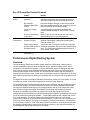
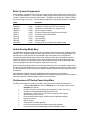
Basic Business Audio System Design Guide
The Basic System Components
Microphones
EV has a complete line of microphones for paging and announcing. The models range from
simple single zone gooseneck paging models to microprocessor controlled stations designed to
route announcements to one or more areas simultaneously.
Signal Routing and Processing
ProAnnounce Signal processing and routing components are extremely flexible to meet any
business audio need. From the comprehensive software functionality to the digital message
manager and easy system control the ProAnnounce components make the installation simple to
specify and install.
Amplification
EV and Dynacord Amplifiers provide exception performance and reliability. The range of
offerings is impressive as well. From the MA series of rack mount mixer amplifiers to the CPS
and ProAnnounce series of power amplifiers any application can be covered.
Speakers
EV offers many installation options for speaker products. From the EVID Premium surface mount
models to the low cost 205/405 series of raw frame ceiling speaker units, we have an option to fit
any installation requirement.
What to Recommend?
In any business audio installation a key part of a well designed job is getting all the steps done
right. Most of these steps must be done in order or the system may turn out to be poorly
designed and won’t meet customer expectations. Getting each step right however can lead to
well done installations which will promote additional future business through positive referrals and
satisfied customers.
Step 1 – Know the Job!
Every system specification begins with a survey of the site. The sales engineer, whose job is to
ask the right questions and gather all the information necessary to complete an accurate bid,
normally performs the survey.
At this stage, it is most important to form an accurate picture of the customer’s needs. Will the
system be used for paging, background music, or both? Do pages originate from a single
location, or from multiple locations? Must the system be tied into the customer’s telephone
network? Should the system be divided into multiple zones with separate volume controls? If so,
should pages be routed to all zones, or should zones be separately addressable? Should zone
controls be located at the rack, or is local control required? The answers to questions like these
will determine major aspects of the system design.
Talking to individual users of the proposed system will help to reveal important design details. Is
the maitre d’ hotel’s station located directly under a speaker? If so, then an independent local
volume control should be provided for that speaker, so that it can be adjusted to allow
conversation with patrons. Will the person issuing pages be sitting under or near a speaker? If
so, then consider equalization, or a separate muting circuit, to avoid feedback. Is light-switch
height a comfortable location for zone volume controls, or does the user have another
ElectroVoice/Dynacord BGM Guide
Page 14
preference? Getting this kind of information at the beginning will help to avoid confusion and
delays at the installation stage.
Just as important as the human factors are the construction details of the site. How are the walls
and ceilings constructed? What kinds of mounting surfaces will be encountered? Is the drop
ceiling a lay-in type, or tongue-and-groove? Where must cabling be routed, and how accessible
are those spaces? Do partition walls or bearing members extend above the drop ceiling, where
they may obstruct cable runs? Is conduit or plenum cable required? All of these factors directly
affect the price quote and the actual task of installation.
A key decision early on in evaluating the equipment requirements is what type of infrastructure
the system should have. The decision will determine if a mixer amplifier is used for the
installation or if the ProAnnounce digital matrix routing system is used. The key questions to ask
consist of the following:
1. Are there more than 2 independent audio programs running simultaneously?
2. Are “zone specific” independent remote controls required for volume levels in each zone?
3. Is the ability to remotely switch program sources for a particular zone required in more than
one zone?
4. Do voice pages and announcements need to be restricted to certain areas of the building?
5. Is remote off site control of the system a required feature?
6. Are the power requirements for the system greater than 600 watts?
If the answer to any one of these questions is yes there is a good possibility that the
ProAnnounce digital matrix infrastructure is required. The additional cost for this system however
is not that great. The typical premium for a ProAnnounce routing system is less than $1,200 for
most installations over that of a “discrete” system design. In many cases there is no other viable
solution to accomplish what the client wants.
Step 2 – Determine the Acoustic Requirements
When the basic infrastructure is established then a system acoustic layout can be done. This
would consist of the following basic steps:
•
•
•
•
•
Establishing required coverage areas
Setting the acoustic volume (SPL) levels desired
Establishing any esthetic or design requirements for the speakers.
Estimating background noise levels for each zone.
Determining the program material content to be run through each zone.
All this is done while taking into account the expectations of the client and the environment in
which the system will be run. Is it a loud sports bar or a quiet elegant restaurant? Or is it a large
open area of a hotel lobby and ballroom? Any of these needs can sway the final equipment
selections.
At this point you need to determine the number of speaker appliances needed for the installation.
This can be done using computer design tools such as the free EV Excel speaker calculator when
using ceiling speakers or EASE which is a full scale acoustic modeling package.
Step 3 – Conduct a Preliminary Layout and “Walk Through”
The third step is to assemble the system design on paper and review the signal paths, amplifier
power requirements and establish the basic functionality of the overall system design. This can
be done with the aid of the ProAnnounce designer software if a pro announce based system is
being employed. If a simpler system is used then often a basic charting package such as Visio is
adequate to lay out the system.
ElectroVoice/Dynacord BGM Guide
Page 15
Step 4 – Assemble the Equipment List
At this point an equipment list needs to be assembled and the hardware portion of the job can be
estimated. Also labor estimates can be done as well after a site inspection has been conducted
and physical layouts to scale have been constructed.
Upon completion of a thorough site survey, the system may be specified and quoted. The sales
engineer may also generate the design and quote, often at the same time as the site survey.
Success at this stage depends upon experience and product knowledge.
To avoid ambiguity and confusion at the installation stage, the specifications need to be as
explicit as possible. Of course, it should enumerate all of the equipment proposed to do the job,
and should include both a block diagram and an accurate floor plan with annotations regarding
construction. In addition, it should provide details such as local volume control locations and
height, the desired location for amp racks, and even names of the employees who are expected
to use the system. To forestall disputes and clarify responsibility if changes are required during or
after installation, the customer should be asked to sign a written agreement governing the
specification.
Many contracting companies simply communicate the sales engineer’s design directly to their
installation department, who are charged with putting the system in and making it work. There are
potential problems with this approach. For example, the salesman’s natural tendency is to overdesign and oversell when he can; if the client is amenable, the result can be an excessively
complicated (and problematic) system. Moreover, it is easy to make mistakes in the flush of a
sale, and these may be compounded when the system goes in.
To address such pitfalls, it makes good sense to have each proposal reviewed by a second
engineering employee whose approval should be required before the specification goes to
installation. At this stage, design details can be fine-tuned and potential problems can be
addressed to assure that the design is feasible, efficient and free of unnecessary redundancy.
Expect The Unexpected
The distributed sound system market is highly competitive and margins are small. It makes good
sense to do everything you can to avoid problems at the installation stage and to be ready to
handle callbacks or last minute changes smoothly. One way to do this is to anticipate problems
before they occur and build contingency plans into your operation.
For example you should always have some inexpensive “fixes” at the ready. Say that the
customer decides to change his floor plan at the last minute, requiring you to add another zone to
the system. You can offer an additional MA series shelf-mount mixer/amplifier that enables you to
offer a painless quote for the requested change, and come out a hero. You can even avoid the
additional cost of installing a volume control in the new zone by putting the amplifier on a shelf in
the zone.
Similarly, it may make sense to pull a couple of extra cable pairs (both speaker lines and mike
lines) when making your home runs. That way, if there’s a base that wasn’t covered in the
specification, you can make it up onsite. The practice also facilitates expanding the system at a
later date.
Be sure that the floor plans you use are up-to-date, and keep communications open with the
client. Particularly if you are limited to using existing wiring, you need to know if the client’s plans
for space usage will remain the same. Otherwise, you may end up with a real headache — like
having the emergency room announcements directed to the pediatric ward
Finally, it is vitally important to be sure that you know who in the client’s company is authorized to
make decisions when questions arise on the job site. If the building manager tells your installers
to put the amp racks in the basement you don’t want the owners calling you and insisting that
they should have been in the second floor office
ElectroVoice/Dynacord BGM Guide
Page 16
Standardizing for Profitability
One of the best strategies that we can recommend for success in contracting is to standardize
your operations wherever possible. Settle on a few basic system designs that can be modified to
cover a wide variety of circumstances and then educate your sales staff about them. Develop
standard pricing calculations, in cost per hour, for all of the basic labor items — putting in a can,
pulling a cable pair, installing a plenum run, and so on. Rather than trying out a new, whiz-bang
esoteric product on each installation, stock a carefully selected complement of proven performers
and use them consistently. Often you can achieve significant savings by reducing the number of
suppliers whose products you use. When you use several suppliers, you encounter differing lead
times, minimum order quantity requirements, freight policies and payment terms that complicate
your ability to respond quickly and consistently to demands from your customers. These are
“hidden” overhead costs that affect your ability to generate a profit.
Speaker Selection
Distributed loudspeaker systems for paging and background music are among the most important
“bread and butter jobs in sound contracting. In most cities, new restaurants, hotels, health clubs
and clinics are continually sprouting up. Each one has needs that can be met by a distributed
system, and each represents a potential client for the enterprising contractor.
The overwhelming majority of paging and background systems are relatively small, however. With
the margin on many installations running in the $400 to $600 range, there’s not much room for
error or misunderstanding, since the cost of a single callback can eat up most of the profits. To
succeed with distributed sound systems, the professional contractor needs to be able to count on
his jobs going in smoothly and efficiently.
In this article, we’ll explore some of the “nuts and bolts” issues that affect profitability in the
distributed sound system market, and offer suggestions for improving your chances of success in
the business.
Ceiling vs. Surface Mount Systems
Several factors will determine the choice of surface mount or flush mount (ceiling) speakers for a
given job. The most common criteria are:
•
•
•
•
Audio coverage requirements
Audio performance needs
Building structure design
Esthetic requirements of the environment
Evaluating the choices among these primary criteria will often determine the format which is
required for a listening area. It is important to note here that any installation may employ both
types of products for different areas or to meet certain performance needs. For example to gain
more control over sound coverage surface mount speakers may be employed but ceiling mount
subwoofers may be utilized to keep the esthetic “footprint” or design impact of the speakers on
the space relatively small.
Selecting & Positioning Ceiling Loudspeakers
In the traditional approach to overhead-distributed systems, loudspeakers are located in a grid
arrangement whose dimensions are dictated by the room height and the directivity of the speaker
elements. Two basic placement patterns prevail: square spacing, and hexagonal (or crisscross)
spacing.
In addition to the spacing pattern, the designer must choose between three density types,
designated respectively as edge-to-edge, minimum overlap and center-to-center (see Figure 1).
The greater the overlap, the more uniform the coverage — and the higher the cost. Budgetary
ElectroVoice/Dynacord BGM Guide
Page 17
constraints tend to favor sacrificing density, so the optimum center-to-center configuration is, in
practice, the least common of the three.
Ceiling Speaker Coverage
The main objectives in deciding about the placement pattern and density of loudspeakers in a
distributed system are covering the area effectively, providing sound that is audible and intelligible
over the entire listening area, and making sure the system is capable of sustaining whatever
average and peak sound pressure levels the application requires.
A misunderstanding about the coverage angle specification of loudspeakers can easily result in
system design mistakes. It is very common to see a “polar coverage” spec and assume that the
speaker will actually cover this angle. Loudspeakers actually cover less area than their spec
sheets would imply. (Let me clarify that the coverage angle is typically the angle at which the
sound level is 6 dB down from the on-axis sound level.)
Polar vs. Listening-Plane Coverage. There are two different types of coverage measurements
that often get confused for one another. It is standard in the loudspeaker industry to state the
coverage in a polar pattern — in a sphere that is 1 meter from the speaker in all directions. The
angle where the sound level is down 6 dB from the on-axis level is called the edge of the polar
coverage pattern. This is what appears on spec sheets.
It's a legitimate specification, but it does not represent what the coverage will be over a flat
listening plane, as in any room, because it doesn't take into account the difference in distances
that people are from the speaker. For speakers projecting from a ceiling onto a flat listening
plane, the sound has to travel farther off-axis (to the sides) than it travels on-axis (directly below
the speaker) resulting in a much greater drop-off of sound level off-axis. The result is that the
actual coverage angle (at -6 dB) on the listening plane is more narrow than the polar spec. Some
ceiling speaker manufacturers use their polar measurement to claim extraordinarily wide
coverage. Do not use this specification to lay out coverage patterns of ceiling speakers!
To Illustrate. Imagine a loudspeaker with a 180° polar spec. If you were to incorrectly interpret this
as 180° coverage on the listening plane, then one speaker would be all you would ever need for
any application. But imagine a single speaker trying to cover an entire department store or
restaurant. In fact, you will see that unless a speaker can send more sound to the sides than it
does directly on-axis, it never covers more than 120°.
The sound system designer needs to work with the actual coverage over a flat listening plane
because that is the plane in which we live, listening at a height of 3 to 6 feet above the floor,
depending on how tall we are and whether we're standing or seated. This is called the listeningplane coverage specification of the speaker. The listening-plane spec represents the reality of the
speaker's coverage for the listeners. Laws of physics dictate that the listening-plane coverage is
always more narrow than the polar coverage pattern.
Let’s take a speaker that has a 140° polar coverage (i.e., its 6dB down points) as an example. It
would be a mistake to assume that this speaker can cover 140° over the listening plane. In fact,
the level at the edges of a 140° pattern is actually more than 15 dB down compared to on-axis —
not 6 dB down. It's interesting to note that the same proportions hold true for any ceiling height:
No matter how high the ceiling is, the off-axis distance is even farther away by the same
proportion. So for the loudspeaker in this example, whether the ceiling height is 8 feet or 20 feet,
the listener who is at the edge of the 140° pattern, who you might think is at the 6dB down point is
really 15 dB down.
The actual listening-plane coverage depends on the polar plot of each speaker. On average, the
coverage of the listening plane from a speaker with a 140° polar coverage is usually between 90°
and 110° .
ElectroVoice/Dynacord BGM Guide
Page 18
Converting Coverage Specs to A Layout
How do you convert polar coverage to listening-plane coverage as you design sound systems?
There are two ways. One is to use the EV ceiling speaker layout program that does the
conversion for you. For more elaborate analysis you can use EASE. Ease can determine
intelligibility and map the SPL output of your entire installation. Usually that's not necessary
however, as you can easily do a little bit of math and figure out what the real listening plane
coverage angle of the speaker is.
The second way to compute the listening-plane coverage is to start with the exact polar plot of the
speaker and use a conversion table. (Real polar plots directly from test equipment are more
accurate than an artists' redrawing.) Polar plots are usually normalized to the on-axis value,
which is usually labeled “0 dB.” For every angle off-axis, there is a “difference-figure” between this
normalized on-axis value and the volume at that angle.
To convert to listening-plane coverage, add the 3dB Correction Factor figure from Table 1 for that
angle off-axis to the figure from the polar plot. If you're doing this correctly, the coverage pattern
is getting more narrow than the original polar plot.
By using the actual polar plot of the speaker and applying these correction factors from the chart,
the angle that results in a figure of -6 dB is the angle of coverage for the speaker. This angle is
the real 6dB-down angle for that loudspeaker when it is projected onto the listening plane.
Remember that this coverage angle is valid regardless of the ceiling height.
If we take the polar plot of a hypothetical speaker with 140° coverage, we see that at 70° off-axis
(140° total for both sides) the level is down 6 dB compared to the on-axis level. By looking at the
polar-to-listening-plane conversion chart, we need to add -9.3 dB to this -6dB figure to find the
actual level on the listening plane at this off-axis angle. We find that the level of this 140° speaker
(as specified by the polar coverage) is actually -15.3 dB, not -6 dB, down at 70° off-axis.
Therefore, listeners located at this off-axis angle will hear sound that is more than 15 dB down
from the level they hear when they pass directly underneath the speaker. This is a very large
difference. Keep in mind that these coverage angles are averaged over the frequency spectrum
and will generally not give the rated coverage at every specific frequency.
To find the actual 6dB down point of the speaker for the listening plane, take the actual polar plot
of the speaker and at every increment of 5° off-axis, apply the correction factors from the polar-tolistening-plane conversion chart. The 6dB-down angle is that angle at which the new figure reads
-6dB (polar dB down plus the additional dB down from the correction factor). While the final
resulting angle depends on the actual polar plot of the speaker, it can generally be said that most
speakers with a nominal polar coverage of 140° can be expected to reach -6dB between 45° and
55° off-axis, resulting in an actual listening-plane coverage between 90° and 110°.
Now let's take a speaker that has a 180° polar coverage. Let's further assume that it is a mythical
“perfect” speaker where the volume doesn't go down at all at any angle. Its polar pattern when
placed in a ceiling is a perfect half-circle. To find the real 6dB-down point, we apply the correction
factors and find that at 60° off axis (120° coverage), the sound is 6 dB down. Therefore, the real
listening-plane coverage of a perfect 180° speaker is only 120°. Now, let's realize that a speaker
with a 180° polar coverage “spec” can actually be down 6 dB at full off-axis and still have a spec
of 180°. In this case, its coverage is going to be even less than 120°.
An Example of Coverage Pattern vs. Speaker Size
For installations involving basic low level background music and paging, system designers often
specify 8-inch cone loudspeakers for distributed overhead systems, at least in part because they
represent the traditional choice. In many cases, however, you can achieve equal or better results
— at a significant savings — by using specially designed 4-inch elements. Characterized by
somewhat smoother frequency response and less susceptibility to feedback than 8-inch
elements, 4-inch units are also generally less expensive and offer a real advantage in reduced
directivity.
ElectroVoice/Dynacord BGM Guide
Page 19
The EVID C4.2 is just such a 4” speaker. The effect of the C4.2’s wider dispersion is indicated in
the figure at the right. In applications where reverberation is not an issue, the C4.2 (shown with
coverage pattern “A”) offers greater overlap and, thus, more uniform coverage than an 8-inch unit
(coverage pattern “B”). When specifying a
new system, you can take advantage of the
C4.2’s wider dispersion to decrease the
number of speakers required to cover a
given area. This will result in even greater
savings.
Of course, a 4-inch unit will typically be
somewhat less sensitive than a comparable
8-inch: for equivalent motor assemblies, the
difference is on the order of 3 dB. The 4-inch
will also have slightly reduced low-frequency
capabilities.
A= C4.2 4-inch speaker @ 4000 Hz
B=Typical 8-inch speaker @ 4000 Hz
Neither of these factors is a significant problem in most distributed systems, however. The C4.2 is
conservatively rated to handle far greater power than most standard 8-inch units so its continuous
SPL output will be more than adequate. Moreover, its reduced output below 150 Hz actually gives
it an edge in intelligibility, since low-frequency energy is most likely to excite ambient
reverberation. For these reasons, the C4.2 represents a great way for you to improve the
performance of your distributed systems while maintaining a competitive edge in price quotes.
When Controlled Coverage is Needed
In some installations coverage control is clearly essential to maintain intelligibility and listenability.
In these cases a speaker which provides controlled coverage over as wide a bandwidth as
possible is needed. In live room environments the reflection of sound off of walls can be a major
cause of intelligibility problems. The two examples below illustrate the effect of speaker
dispersion in a room. The first example is the EVID C8.2 speaker with it’s 110 degree coverage
pattern at 1kHz. The next illustration is the controlled coverage EVID C8.2HC unit with it’s 75
degree spec. As you can see the effect of the controlled coverage in the C8.2HC has a dramatic
effect on the energy spilled onto the walls. The result will be a more intelligible installation using
the C8.2HC.
C8.2 Speaker Coverage at 2kHz
C8.2HC Speaker Coverage at 2kHz
The Use of Subwoofers
Subwoofers are an important part of an outstanding business music system. Light background or
foreground music might not require subwoofers; however, even in systems where the bass
doesn't need to be a dominant factor, having clear low frequencies can make a big difference in
the customers' enjoyment of the music.
The number of subwoofers to use, where to position them, how to set the taps (on 70V/100V
subs) and how loud to run them vary depending on the characteristics of each installation. Criteria
ElectroVoice/Dynacord BGM Guide
Page 20
such as speaker placement, boundary loading (are speakers placed close to a wall or in a
corner?), size of the room, coupling of multiple speakers/subwoofers, reverberance of the room,
the type of music, the type of activity and the expectations of the listeners all come into play.
Positioning Subwoofer Components
Hanging a subwoofer in the middle of a room results in the lowest possible output from the
subwoofer. Placing a subwoofer at the ceiling, wall or floor increases its output. Placing it within a
few feet of a 2-boundary junction (like a ceiling/wall junction or a wall/wall junction) increases its
output further. Placement within 3 feet of a corner increases its output still more. In these cases,
there is both an increase in sensitivity (output per watt of input) and in maximum total SPL
capability. This can help in getting as much sound as possible from a few subwoofers. However,
there is a potential pitfall in placing a subwoofer in a corner: You can wind up with uneven bass
coverage in the room.
Because there are often so few subwoofers, you can have a problem getting even coverage of
the space. People sitting or standing very close to the subwoofer are going to hear excessive
lows while people who are father away might not be getting enough.
To resolve this problem keep in mind that as you move farther from the sub, the volume drops
off, typically at 6 dB per doubling of distance. Then, when you reach a certain distance, the
subwoofer level stops dropping off at such a high rate. This is called the critical distance, which is
where the reverberant field within the room equals the direct sound from the subwoofer. The
critical distance depends on how reverberant the room is. As you get farther past critical distance,
even though the level of the subwoofer doesn't drop off nearly as quickly, the quality of the
subwoofer sound might not be as good. But even though this may happen, it's sometimes
acceptable for subwoofers in business music applications.
One way to make the subwoofer coverage as even as possible is to use more than one. In many
places, it's a good idea to add a second subwoofer, or more. Even if you don't need additional
subwoofers for volume reasons, you might want to consider them just for evenness of subwoofer
coverage. Generally, if you have to use just one subwoofer, it is best to sacrifice the sensitivity
increase and place the subwoofer for most even coverage, as long as you can achieve the SPL
goals.
Choosing the Best Mixer/Amplifier
Practical distributed sound system installations almost always require the ability to handle
multiple signal inputs. Pages may originate from two or more sources, the telephone system and
a hand-held microphone, for example. Background music from two selectable sources, with
muting keyed to the paging input(s), may also be required. There may even be a need for a lowlevel noise-masking signal mixed in with the other signals at a consistent, adjustable level.
For these reasons, combined mixer/amplifiers are commonplace in sound contracting. Designed
to handle several audio inputs at different signal levels and source impedances, such units
incorporate mixing and automatic muting along with amplification. By efficiently consolidating
often-used functions in a single enclosure, they greatly simplify routine installations, reducing
costs and increasing reliability.
In this article, we examine the criteria for selecting mixer/amplifiers, describe the range of alternatives offered by ElectroVoice Sound, and suggest applications for each. Our aim is to encourage
appropriate equipment choices to maximize both profitability and customer satisfaction.
Analyzing the Application
The first step in selecting a mixer/amplifier is to examine the demands of the application. What
are the intended uses for the system? Will background or foreground music be required in
addition to paging? If so, from what type of source: FM/AM radio, tape, or both? Where will pages
ElectroVoice/Dynacord BGM Guide
Page 21
originate, and from what type of interface? The answers to questions such as these will help to
determine the input configurations of the unit.
Similarly, take a look at the expected load requirements. For example, how many loudspeakers
will be needed to adequately cover the space and assure good intelligibility? What type of
loudspeakers will best serve the application: ceiling speakers, wall speakers, paging projectors,
or a combination of different elements? Will 25V or 70.7V distribution be necessary, or is a direct
voice coil connection sufficient? Must the system handle multiple independent zones? Such
factors will determine the power output required of the unit.
Additional elements to consider include the level of ambient noise and reverberant characteristics
of the space, along with the frequency response of the sources and loudspeaker elements; these
will affect the audio quality of the system. Packaging also should play a part in your design. Must
controls be user-adjustable, for example, or should they be tamper-proof? Will the mixer/amplifier
be rack-mounted with other equipment? Must the system operate in a dusty or moist
environment, or where users will have dirty hands or be inexperienced? Finally, remember the
bottom line: what percentage of the cost of materials sold on the job is represented by the cost of
the unit? Once you have initially specified the requirements of the system, you can narrow down
your choice of mixer/amplifiers for the job.
ElectroVoice offers two mixer/amplifiers designed to suit a wide variety of sound contracting
needs. The MA1212 or 1206 units are mixer/amplifiers with either 120 or 60-watt output
capabilities. Mountable on a shelf or in a rack, these units accommodate up to 12 different input
sources to permit larger complex configurations with off-the-shelf convenience. Tone controls are
provided, along with outputs to drive supplementary systems such as booster amps or tape
recorders.
When To Specify Mixer/Amplifiers
The performance of integrated Mixer/Amplifiers is more than adequate for the vast majority of
distributed sound installations.
Consider, for example, the question of frequency response. The MA models exhibit a lowfrequency limit of 50 Hz, and an upper-frequency limit between 15 and 20 kHz. Is this good
enough? To answer this question, we need to examine the performance of other components in
the signal chain.
Let’s examine the response of a typical 8-inch ceiling speaker in a 1.8 ft3. sealed box. At the low
end, the unit begins rolling off below about 150 Hz and is nearly 20 dB down by 50 Hz. Its
response also rolls off above 5 kHz, and is nearly 10 dB down at 20 kHz. Paging projectors, used
in a wide variety of industrial applications, will introduce even more severe response limitations,
along with greater harmonic distortion.
Similar conditions apply at the system input. Background music players and FM stations, for example, are limited to the bandwidth from 50 Hz to 15 kHz, at best. Push-to-talk paging
microphones, such as the ElectroVoice US600EL, are tailored for the voice range and thus
feature far more limited frequency response. Telephone paging lines are further limited in
response, and can introduce greater distortion.
Remember that using an amplifier with significantly wider bandwidth than the signal source and/or
output devices will serve primarily to increase noise and distortion in the system. An amplifier
which reproduces low frequencies below 200 Hz when driving a paging projector with a 300 Hz to
500 Hz lower cutoff will be wasting power (reducing headroom in the pass-band) and may cause
intermodulation distortion if not premature failure in the paging projector. In this context, the audio
specifications of the utility units in our example begin to look appealing. In fact, whenever the
program source, paging mic or loudspeaker system exhibits limited bandwidth, there is a
diminished need for an audiophile-quality mixer/amplifier system. The majority of practical
installations fall within this category. In professional buildings, office structures, warehouse paging
ElectroVoice/Dynacord BGM Guide
Page 22
systems and outdoor installations, a utility model will serve the client’s needs just as well, and
decrease the equipment costs.
Approached methodically and logically, the choosing of a mixer/ amplifier for a distributed sound
system can be a painless and efficient process. Don’t select a “pro spec” unit when all you need
is a utility amp; you’ll be wasting money and it won’t do the job any better. As we have shown, by
applying a little analytical thought and care, you can satisfy clients’ needs while keeping costs in
line. And that’s what the sound contracting business is all about.
When the Job Calls For ProAnnounce!
When the system specification calls out for a routed zoned system then ProAnnounce is the best
avenue. There are a few key decisions to make to determine the basic equipment makeup of the
installation.
First, the design process and site survey should have established the basic signal structure of the
installation. This will define if a DRM4000 8x2 unit is sufficient or if one or more of the powerful
DPM4000 4x4 routers are called for. If the installation calls for a DPM4000 unit you must
determine if more than a single DPM4000 is needed and what input cards are required. Second,
if additional zones beyond the basic 4 are being used then the DCS 400 system is required. This
allows for a large, extended, relay controlled routing network for paging. Third, if automatic
messaging is desired then a DMM4650 may need to be added. This will provide additional
flexibility for prerecorded announcements and signals. Finally, if any additional external controls
are being added (remote audio volume or source switching for example) then the appropriate
DCS control module will be needed.
The DRM4000 vs. the DPM4000
In order to determine which cpu is best for an installation the designer needs a good working
understanding or each of the units capabilities. To better understand the difference between the
DRM4000 and the DPM4000 an overview of each is provided below.
DPM4000 4x4 Matrix Router
The DPM4000 is essentially a 4 x 4 digital matrix with added DSP capabilities. Actually, when you
factor in the internal alarm/chime functions, message stacking, and pre-recorded message
functions it is more like a 7 x 4 matrix. Processing in the form of level and EQ is provided on each
of the four external inputs to the system. In addition, level and optional delay is provided on each
of the four outputs in the system. Analog compression is also available on certain input cards, as
well as, the paging stations. The DPM 4000 can be configured to perform tasks based on a
variety of control inputs. Likewise the DPM 4000 can provide a variety of control outputs.
Examples of these inputs and outputs might be: a contact closure from a fire alarm results in an
alarm and voice message automatically sent to the loudspeaker system, pressing a button on a
paging station or wall control raises or lowers a video screen and turns on or off the video
projector, a maintenance worker uses his cell phone to turn the lights on or off in a given area of a
building, an amplifier failure is detected, a backup amplifier is switched into operation and
maintenance personnel are notified of the failure. The possibilities are only limited by one’s
imagination and ingenuity. The DPM 4000 can be configured for a variety of audio routing tasks in
addition to the normal paging applications. The unit is especially suited for background music
applications in such venues as restaurants, shopping centers, and specialty stores. The DPM
4000 can even be used for very small room combining applications (up to four rooms).
DRM 4000 Mixer
Unlike the DPM4000, the DRM4000 can be used with very little preprogramming. Many of the
functions are externally selectable or adjustable. The DRM4000 can be used either in a standalone mode or in conjunction with the DPM 4000. The DRM 4000 can be used to enhance the
DPM 4000’s input and output capabilities. The DRM 4000 features eight stereo RCA inputs, four
ElectroVoice/Dynacord BGM Guide
Page 23
XLR mic/line inputs, eight GPI control inputs, two XLR outputs capable of either independent or
stereo operation, and two VCA level inputs. In addition, two of the XLR mic/line inputs can be
configured for paging with adjustable ducking. The DRM 4000 can be programmed to change its
configuration through presets assigned to the GPI inputs, PC control (RS-232), or DPM 4000
control (RS-485). A good example of using the DRM 4000 stand-alone is in a typical
restaurant/bar application. There may be multiple sources such as TV, tuner, CD player, music
server, etc… and you may want a different source in the bar area such as the TV for the big
game, while in the restaurant you might want some jazz playing in the background. In addition,
you may want the hostess to be able to selectively page in the bar area for customers that are
waiting for tables in the restaurant.
Volume And Tone Controls / Delays
The ProAnnounce system provides individual volume controls for each input, output, and paging
station. Even the internal audio sources, like gong/alarm tone generators, voice message
playback, and pilot tone generator employ individual level controls, each. Additionally, it is
possible to set an attenuation that unanimously affects the inputs. This value determines the
degree, by which the input signal is attenuated during the reproduction of messages or other
signals with a higher priority setting. This allows to smoothly fade-out and fade-in background
music during the transmission of important messages.
Besides, each of the four inputs embodies three fully parametric digital filters allowing for optimal
tone control. The filters provide different filter types like Hi-/Lo pass filters, shelving filters, and
peak-dip-filters providing the possibility for adjusting the sound within the entire audio
transmission range. Factory-preset filter settings for the DPC 4000 Series paging stations are
already provided.
Setting volume levels and filter parameters is accomplished via PC during the configuration
procedure. Further, it is possible to alter any volume setting during the later operation of the
system via special-function keys on the paging stations or through external controls that are
connected to analog or digital control inputs.
All four outputs employ digital delays allowing signal delays of up to 330 ms per channel. Natural
delays, resulting from loudspeaker positioning, which causes time differences in the arrival of
sounds or environmental circumstances related to architectural characteristics of the location, can
be equalized without additional effort.
Signal Generators / Voice Message Memory
The DPM 4000 provides a variety of tone generators for the generation of gong, alarm, and text
signals. Signal generation is realized through DSP-algorithms, which are extremely flexible in
use, so that they can be adjusted to match nearly any possible application. Factory presets
include 6 different gong signals, 18 different alarm signals, plus sine cycle at any frequency.
Other than in comparable equipment, the ProAnnounce signal generating DSP-algorithms do not
take up any extra storage of the voice message memory.
In addition, a voice message recording/playback module providing CD-quality sound is optionally
available. With a total recording time of approximately 6 minutes, 25 different messages are being
managed. The DPM 4000 provides the possibility to install up to four optional FLASH-memory
modules, depending on individual desires or requirements.
Control Inputs And Outputs
By using the control inputs, it is possible to link the ProAnnounce system to fire alert systems,
burglary alert systems, or to a central operating desk. It is also possible to connect external
switches, breakers, rotary controls or rotary encoders, respectively to query control outputs of
external units (power supplies, power amplifiers).
ElectroVoice/Dynacord BGM Guide
Page 24
The control outputs allow switching external devices ON or OFF, trigger signals and events,
switch monitor sources, remote control doors, gates or shutters, generate analog signals for the
control of multimedia systems, etc.
A total of 130 control inputs for logic levels, 128 control inputs for analog levels, 16 inputs for
rotary encoders, 127 logic-control outputs, and 128 analog-control outputs are usable.
Clock / Calendar
The ProAnnounce manager DPM 4000 has an integrated quartz-controlled real-time clock which
can be set for automatic operation. The system clock automatically recognizes leap years and, if
in auto mode, automatically switches between daylight saving time and standard time.
The system clock provides the possibility to control up to 40 external slave clocks. For this
purpose, the DPM 4000 employs a special, short-circuit-proof output for pole changing impulses.
Slave clocks are automatically re-synchronized whenever a time difference to the system clock is
detected; like for instance in cases of power outage or when time values were entered manually.
It is possible to activate pre-set functions like break-gong signals, background music, remotely
controlled gates, switch lights ON/OFF, etc., when using system clock and calendar functions
together. All the functions mentioned before can be programmed for specific days; but also
hourly, daily, weekly, monthly, and yearly activation is possible. Up to 500 time-controlled events
can be programmed.
Monitoring
The ProAnnounce manager DPM 4000 embodies a monitor amplifier with headphones/speaker
output. The integrated logic-switching circuit provides the opportunity to listen to the signals of
any internal input and output. Assigning external sound sources to the monitor bus is possible as
well. This additionally allows monitoring amplifier outputs or pre-listen to the contents of external
voice message memories and other audio devices.
The remote control’s wiring already includes all the cabling necessary for the pre-/post-listen
feature when using remote-controlled amplifiers. In addition, when using the DCS 420
ProAnnounce MONITOR MANAGER, additional programming operating flexibility is available.
Macros
Macro is defined as the combination of several commands, functions, and their parameters in an
internal consecutive sequence. For example a gong signal with specific volume and priority
settings has to be transmitted in different calling zones, while simultaneously activating a control
output. In that case the macro consists of the functions “gong” and "control" with the parameters
gong-type, volume setting, priority number, calling zone numbers, and the type and id-number of
the control output.
It is possible to initiate a macro via the special function keys on the paging consoles or to trigger it
via control input. It is also possible to combine a macro with the internal clock or calendar.
The ProAnnounce system provides a number of pre-programmed macros, where only individual
parameters still have to be entered. Additionally, it is possible to combine several macros in a
sequence. Using pre-defined macros and sequences lets you create new, user-specified and
application-related macros, which basically are capable of managing any control function
imaginable. A total of up to 250 user-macros can be programmed.
Interfaces
Besides its control inputs and control outputs, the ProAnnounce system provides additional
interface ports. The connection of paging consoles to the ProAnnounce manager DPM 4000 is
performed via serial RS-485 ports. This allows connecting up to four terminals at a single port.
ElectroVoice/Dynacord BGM Guide
Page 25
Power amplifiers and the DCS 400 controller are connected to another independent RS-485 port,
which allows direct management of up to 64 power amplifiers and 8 DCS 401.
Connecting a PC is established via serial RS-232 port on the rear panel of the DPM 4000. It is not
necessary for the PC to be permanently connected to the DPM 4000.
An additional RS 485-interface offers the possibility to operate several DPM 4000 in a network.
Station Control Consoles
The ProAnnounce system includes 5 different models of DPC 4000 Series paging stations and
one paging station extension. All microphone terminals employ gooseneck microphones, 6 or 8
function keys and a covered alarm key. An additional alarm key and a key-locked switch can be
retrofitted. The paging stations are available with 10, 20, 30, or 50 selection keys. All models also
employ LC-displays (2 lines with 16 characters each).
The following list provides you with an overview of available paging station models:
DPC 4106
DPC 4510
DPC 4520
DPC 4530
DPC 4550
DPC 4350
6 function keys
8 function keys + 10 selection keys + alarm key
8 function keys + 20 selection keys + alarm key
8 function keys + 30 selection keys + alarm key
8 function keys + 50 selection keys + alarm key
paging console extension with 50 selection keys
All consoles include the following common features:
•
•
•
•
•
•
•
•
•
•
•
•
•
•
•
all functions are processor-controlled
configuration data is stored in non-volatile FLASH RAM
condenser microphone with pre-amplifier and compressor / limiter circuitry
freely programmable key-assignment
easy key-labeling through label-strips and MS WORD™ templates
analog circuitry surveillance via integrated pilot tone generator
processor surveillance via watchdog function
line surveillance via pilot tone and polling functions
covered alarm key (not with DPC 4106)
additional alarm keys or key-locked switches can be optionally retrofitted
connection of an external PTT-microphone or audio source
piezo buzzer for acoustical alerts
an optional loudspeaker can be retrofitted
setup-mode allows direct parameter setting at the paging station
two-line LC-display
All paging consoles are processor-controlled and extensive monitoring functions are provided.
The watchdog function monitors the processor system while a switchable pilot tone generator
monitors the audio section. Additionally, the internal supply voltage is constantly measured. When
it falls below a critical threshold an alert message is being displayed. The line surveillance
function recognizes any line-interruption and/or short-circuits in the audio and RS-485 control
cabling. Upon the detection of failure a corresponding message is displayed.
Understanding DCS Expansion Options
The ProAnnounce™ DCS expansion system uses a variety of cards for control, monitoring, and
routing purposes. These cards are available in two versions. The standard DCS 4xx versions are
circuit cards or modules that mount on standoffs and interconnect via flat ribbon cables. The DCS
4xxR cards are identical in function to the standard cards, but use a card cage with a backplane
for interconnection. The ProAnnounce™ Designer software only refers to the standard DCS 4xx
cards, however they are interchangeable.
ElectroVoice/Dynacord BGM Guide
Page 26
The DCS 400 Expansion Chassis
The DCS 400 expansion chassis uses essentially the same techniques for installing the
cards/modules as is used when installing cards in the DPM 4000. The left-most card (as viewed
from the rear) is always either a DCS 401R controller card, or a DCS 405R extension card. The
DCS 405R cards are used to expand from one DCS 400 chassis to another. The way this works
is that the DCS 405R is the last card in the first DCS 400 chassis (the one with a DCS 401R card
in the left-most slot). The first card in the expansion DCS 400 chassis is a DCS 405R. Cables are
attached between the two cards. While most installations do not require expansion chassis, there
are times when the number of cards under the control of a single DCS 401R exceeds the ten card
limit of a DCS 400 chassis. Relay Wiring DCS 408/409 and DCS 408R/409R relay cards are used
for a variety of applications in the ProAnnounce™ system. One of the primary uses for them is
the control of line or speaker level audio. The DCS 409/409R is used for low voltage and line
level audio signal switching. The DCS 408/408R is used for high voltage and speaker level audio
signal switching. Both cards ship with a number of wire jumpers installed to create a common
buss. Depending on your needs the cards may work without the need to remove any of the
jumpers, however some applications will require that you do so. Complete isolation of the relays
is possible if all of the buss jumpers associated with that relay are removed.
BGM and Paging System Designs
The following pages show a variety of system examples using all of the components we have
talked about in the preceding pages. These systems are practical, real world, examples you can
adapt and use for your own installations.
ElectroVoice/Dynacord BGM Guide
Page 27
BGM Installations - System Examples
Retail Store – Single Zone
This basic retail example illustrates a simple installation to control 3 sources within a single zone
of audio in a 2,500 sq ft space. The system has one paging microphone at the cashiers desk
and telephone paging can be implemented if necessary through the phone system. There is a
background music source consisting of a CD player.
The C4.2’s are tapped at 7.5 watts and the C10.1 is tapped at 30 watts.
System Layout
C4.2
CD Player
Subwoofer
Paging Mic 1- Cashier
Paging Mic 2 - Stockroom
C10.1
Telephone Paging
System Equipment List
Model
Location
Description
Quantity
SPEAKER SYSTEMS
EVID C4.2
Main
EVID C4.2
Restrooms
EVID C10.1
Main
Ceiling Speaker
Ceiling Speaker
Subwoofer
3
1
1
Amplification
MA1212
Office
Mixer/Amplifier
1
OTHER RELATED EQUIPMENT
Various
Rack/Misc
Various
CD Player/Tuner
Various
Wire
ElectroVoice/Dynacord BGM Guide
1
1
1
Page 28
Office Building - 5 Zone - Simplified system
Layout Overview
This very basic office building example illustrates the interconnectivity and flexibility of these
components. Here we take a stand-alone ProAnnounce DCS408 card and have it do the zone
switching for a basic paging only system. The 408 card routes the signals to one of the 5
amplifier channels. The zone selection is controlled via the MP756 11 zone desk microphone.
A combination of C4.2’s and PA430t’s are used in this installation.
System Diagram
Radio Tuner
Zone 1
Zone 3
Microphone
Line
MA606
Zone 2
Zone 4
Zone Control lines
DAP4410
MP756
To Power Amp
DCS 408 Card
From Line Out
Zone 5
24v Power
supply
Equipment List
Model
Location
SPEAKER SYSTEMS
PA430t
Various
EVID C4.2
Various
Description
Paging Horn
Ceiling Speaker
Quantity
2
5
PROANNOUNCE EQUIPMENT
MA606
Office
60 watt mixer/amplifer
DPA4410
Office
4x100 power amplifier
MP756
Office
Paging Microphone
DCS408
Office
Relay card
DPP4002
Office
Power supply
1
1
2
1
1
OTHER RELATED EQUIPMENT
Various
Rack/Misc
Various
CD Player/Tuner
Various
Wire
1
1
1
ElectroVoice/Dynacord BGM Guide
Page 29
Bar-Restaurant - 2 Zone
Layout Overview
This basic bar/restaurant example illustrates a simple installation to control 3 sources and 2
zones of audio within a 7,500 sq ft building. It demonstrates the effective use of the DRM4000
router for a basic 2 zone BGM system. The two zones consist of one for the bar area and the
other for the main dining room. The system also has one paging station at the hostess stand.
The three sources are for a music server, tuner and television audio.
The C4.2’s are tapped at 7.5 watts, the 4.2t’s at 15 watts and the C10.1 is set at 8 ohms.
System Diagram
Main Restaurant
Radio Tuner
Remote
Control
C4.2
Main Restaurant
CD Server
DRM4000
Sports Bar F.R.
Sports Bar
Hostess
4.2t
DPA4410
Office
Remote
Control
C10.1
Sports Bar Sub
E quipment List
Model
Location
SPEAKER SYSTEMS
EVID 4.2t
Bar
EVID C4.2
Restaurant
EVID C10.1
Bar
Description
Surface Mount Speaker
Ceiling Speaker
Subwoofer
Quantity
2
5
1
PROANNOUNCE EQUIPMENT
DRM4000
Office
8x2 Matrix Router
DPA4410
Office
4 Channel Amplifier
253
Office
Paging Microphone
NRS90258
Office
PC Interface
TBA
Various
Wall Controls
NRS90257
Office
Power supply
1
1
2
1
2
1
OTHER RELATED EQUIPMENT
Various
Rack/Misc
Various
CD Player/Tuner
Various
Wire
1
2
1
ElectroVoice/Dynacord BGM Guide
Page 30
Health Club - 4 Zone
Layout Overview
This example is a small to medium size health club with four separate listening zones and 6
sources. Also present are 3 separate paging areas.
The zones are laid out with 4 zones including a Snack Shop/Retail/Lobby Area, Pool Area,
Exercise room and Spin Room.
The paging stations are located at the main front desk, the exercise room main desk, and the
managers office. The six sources consist of television audio, CD player, digital satellite feed and
2 paging consoles. The DCS420 allows for monitoring of the system and all zones from the
managers office. A DTI2000 is used to enable paging from any in house phone. The C4.2’s are
tapped at 7.5 watts, the 6.2t’s at 60 watts, C10.1 and the 12.1’s are set at 8 ohms.
System Diagram
Radio Tuner
Lobby/Pool
Spin
TV
c4.2
Exercise
CD Server
Exercise Sub
Satillite Feed
Paging Station - Front Desk
Lobby Sub
Paging Station - Exercise Room
Pool- Underwater
C1 0.1
Snack Shop
Spin Room
Pool
Remote
Control
Equipment List
Model
Location
SPEAKER SYSTEMS
EVID 6.2t
Exercise
EVID C4.2
Pool/Lobby
UW30
Pool
EVID 12.1
Spin/Exercise
EVID C10.1
Lobby
Remote
Control
Description
Surface Mount Speaker
Ceiling Speaker
Underwater Speaker
Subwoofer
Subwoofer
Remote
Control
Quantity
8
16
2
4
1
PROANNOUNCE EQUIPMENT
DPM4000
Office
Matrix Manager
DPA4206
Office
2x600 Power Amplifier
DPA4411
Office
4x100 Power Amplifier
DTI2000
Office
Telephone Interface
DPC4510
Office
Paging Console
DPP1004
Office
Power supply
DCS401R
Office
Controller Board
DCS416R
Office
A/D Board
DCS400
Office
DCS Rack
DCS420
Office
Monitoring unit
NRS90218
Office
Output Card
NRS90216
Office
Input Card
NRS90234
Office
Input Card
NRS90240
Zones
Wall Control Module
1
2
1
1
2
1
1
1
1
1
1
1
1
3
OTHER RELATED EQUIPMENT
Rack/Misc
CD Player/Tuner
Wire
1
2
1
ElectroVoice/Dynacord BGM Guide
Page 31
Retail Clothing Store -2 Zone
Layout Overview
This is an example of a typical retail clothing storefront with two separate merchandising areas for
customers. One is the young women’s clothing section tailored more for high school and college
age customers and the other would serve the older 25 to 35 year old women’s segment. Each of
these groups shop differently and have different tastes in clothing, music, and personal interests.
In this example, the music programming is divided into three sources and routes to two different
zones. There is also separate message tracks for promotion announcements present for each
zone geared to the clothing specific to that section. A standard 253 desk microphone provides the
paging capability at the cashier station.
The C4.2’s are tapped at 7.5 watts and the C10.1’s are set at 30 watts.
System Diagram
C10.1
C4.2
CD Player
Womens Clothing
CD Player
Message Manager - Office
Paging Mic - Cashier
Mens Clothing
C10.1
C4.2
Mens Clothing
Womens
Remote
Control
Remote
Control
Equipment List
Model
Location
Description
Quantity
SPEAKER SYSTEMS
EVID C4.2
Mens/Womens Ceiling Speaker
EVID C10.1
Mens/Womens Subwoofer
16
4
PROANNOUNCE EQUIPMENT
DPM4000
Office
DMM4650
Office
DPA4260
Office
253
Cashier
DPP1004
Office
DCS401R
Office
DCS416R
Office
DCS400
Office
NRS90216
Office
NRS90234
Office
NRS90240
Various
Matrix Manager
Message Manager
2x600 watt Power Amplifier
Paging Microphone
Power supply
Controller Board
A/D Board
DCS Rack
Input Card
Input Card
Wall Control Module
1
1
1
1
1
1
1
1
1
1
2
Rack/Misc
CD Player
Wire
1
2
1
OTHER RELATED EQUIPMENT
ElectroVoice/Dynacord BGM Guide
Page 32
Retail Book/Record Store -3 Zone
Layout Overview
To best illustrate a more complex retail BGM installation you a typical large bookstore is a good
example. This system has 5 sources laid out over 3 zones. The zones are for the record shop,
main bookstore and the coffee shop. Each requires distinctly different sound sources. 2 paging
consoles are also used with one located at the main cashiers desk and one in the managers
office.
In this configuration the 3.2t’s and C10.1 are run off of 1 channel of the 4410 amplifier with the (2)
C10.1’s tapped at 30 watts. The (12) C8.2’s are tapped at 15 watts and the (12) C4.2’s are
tapped at 7.5 watts.
System Diagram
Main Sales Floor
Radio Tuner
CD Server 2
CD Sales Floor
Coffee Shop
CD Server 1
Paging Station - Cashier
Coffee Shop Subwoofer
Coffee Shop
Cashier
CD Sales
Remote
Control
Rem ote
Control
Rem ote
Control
Retail Bookstore Equipment List
Model
Description
SPEAKER SYSTEMS
EVID 3.2t
Coffee Shop
EVID C4.2
Main Store
EVID C8.2
CD Sales
EVID C10.1
Coffee Shop
Surface Mount Speaker
Ceiling Speaker
Ceiling Speaker
Subwoofer
Quantity
2
6
6
1
PROANNOUNCE EQUIPMENT
DPM4000
Office
Matrix Manager
DPA4411
Office
4 Channel Amplifier
DPC4510
Office
Paging Console
DPP1004
Office
Power supply
DCS401R
Office
Controller Board
DCS416R
Office
A/D Board
DCS400
Office
DCS Rack
DCS420
Office
Monitoring unit
NRS90216
Office
Input Card
NRS90234
Office
Input Card
NRS90240
Office
Wall Control Module
1
1
1
1
1
1
1
1
1
1
3
OTHER RELATED EQUIPMENT
Rack/Misc
CD Player/Tuner
Wire
1
3
1
ElectroVoice/Dynacord BGM Guide
Page 33
Large Department Store - 6 Zone
Layout Overview
To extend the power of the ProAnnounce routing system the DCS control system can be used to
page to different zones. This system shown here uses such an expansion. In a large department
store many independent programs and zones are needed. This system can accommodate these
requirements. This system has 3 music sources and 4 paging stations laid out over 6 zones.
Each requires distinctly different paging needs. The 4 paging consoles used are located at the 3
main cashiers areas and one in the manager’s office.
In this configuration the 3.2t’s and C10.1’s are run off of the 4410 amplifier with the C10.1’s
tapped at 15 watts. The C4.2’s for the main floor are tapped at 7.5 watts and are run using the
4260 amplifier.
System Diagram
M en sw ear
W om ens clo th ing
W hite g oo ds
A p plia nces
M ain F loo r
C ash ier 3
T ee n clo thin g
C a sh ier 2
C ashie r 1
O ffice
Equipment List
Model
Location
Description
Quantity
SPEAKER SYSTEMS
EVID 3.2t
EVID C4.2
EVID C10.1
Speaker
Ceiling Speaker
Subwoofer
7
15
4
PROANNOUNCE EQUIPMENT
DPM4000
Matrix Manager
DMM4650
Message Manager
DPA4260
2x600 watt Power Amplifier
DPA4410
4x100 watt Power Amplifier
DPP1004
Power supply
DCS401R
Controller Board
DCS408R
Relay Board
DCS416R
A/D Board
DCS400
DCS Rack
NRS90218
Output Card
NRS90216
Input Card
NRS90234
Input Card
NRS90240
Wall Control Module
1
1
1
1
1
1
1
1
1
1
1
1
4
OTHER RELATED EQUIPMENT
Rack/Misc
CD Player
Wire/Misc
1
3
1
ElectroVoice/Dynacord BGM Guide
Page 34
Basic Warehouse - 5 Zone
Layout Overview
The ProAnnounce system can be extremely cost effective as illustrated in this example. This
system allows for flexible paging into 5 different zones with a single dual channel amplifier. This
maximizes flexibility while minimizing cost. This system has 1 BGM feed and 2 paging feeds laid
out over 5 zones. Each requires distinctly different paging needs. The paging console is located
at the main reception desk while the DTI2000 allows for paging through any phone system.
In this configuration the C4.2s are for the office feed while the PA430’s are zoned for different
areas of the warehouse. The system is run through one DPA4260 providing 1200 total watts
System Diagram
Office
C4.2
Shipping
PA430t
Loading Dock
Warehouse
PA430t
Receptionist
PA430t
Lunchroom
C4.2
Equipment List
Model
Location
SPEAKER SYSTEMS
EVID C4.2
PA430t
Description
Ceiling Speaker
Paging Horn
Quantity
20
15
PROANNOUNCE EQUIPMENT
DPM4000
Matrix Manager
DPA4260
2x600 watt Power Amplifier
DPP1004
Power supply
DCS401R
Controller Board
DCS408R
Relay Board
DCS400
DCS Rack
NRS90216
Input Card
NRS90234
Input Card
1
1
1
1
1
1
1
1
OTHER RELATED EQUIPMENT
Rack/Misc
Wire/Misc
1
1
ElectroVoice/Dynacord BGM Guide
Page 35
Multi-Use Warehouse, Factory & Office Facility - 15 Zone
Layout Overview
This example shows how ProAnnounce can be used to control the audio routing for BGM and
paging over a very large facility. The combination of 4 channels of amplification and DCS
expansion components allow for this flexibility. The design calls for separate zoned signal paths
for the warehouse, office, factory and lunchrooms while further zoning is provided in the factory
and office for paging
The 4 paging consoles used are located at the main receptionist, building manger, shipping
station along with the telephone interface to allow for building wide paging operation. In this
configuration the C4.2 ceiling speakers for the office areas are run off of the 4411 amplifier. The
other areas use a combination of Cobraflex IIB’s or PA430t’s for paging notification using the
bridged 200 watt channel of the 4411 with one 4140 amplifier.
System Diagram
C4.2
C4.2
Office
C10.1
PA430t
Shipping
Eingineering
Loading Dock
PA430t
C4.2
Lunchroom
Receptionist
Factory
Floor
Shipping
Zones 1-5
Warehouse
Metal
Fab
Zones 6-8
Warehouse
Building
Manager
Cobra
IIB
Factory
Floor Manager
PA430t
Cobra
IIB
PA430t
Equipment List
Model
Description
Quantity
SPEAKER SYSTEMS
PA430t
Paging Horn
Cobra IIIB
Paging Horn w/ID60DT
EVID C4.2
Ceiling Speaker
EVID C10.1
Subwoofer
16
4
30
2
OTHER RELATED EQUIPMENT
Rack/Misc
CD Player
Wire/Misc
1
3
1
ElectroVoice/Dynacord BGM Guide
Model
Description
PROANNOUNCE EQUIPMENT
DPM4000
Matrix Manager
DMM4650
Message Manager
DPA4140
2x600 watt Power Amplifier
DPA4411
4x100 watt Power Amplifier
DPP4004
Power supply
DCS401R
Controller Board
DCS408R
Relay Board
DCS400
DCS Rack
DCS420
Monitor Station
NRS90218
Output Card
NRS90216
Input Card
NRS90234
Input Card
Quantity
1
1
1
1
1
1
3
1
1
1
1
1
Page 36
Appendix A: Distributed Audio Systems – A Primer
The technique of constant-voltage (CV) loudspeaker distribution has been a standard audio
practice since the earliest days of sound contracting.
Why Is It Called “Constant Voltage”?
You may have heard a distributed speaker system referred to as a “70-volt constant voltage
system.” Does this mean that there is a constant AC or DC voltage of 70 volts always going
through the speaker line? No, it doesn't.
I've heard that the term goes back to early telephone systems. Audio engineers of that time were
concerned with how the voltage arriving at the receiving device varied from the voltage sent out
by the sending device, and how the voltage transfer would vary in conjunction with changes in the
impedance of the receiving device. In distributed speaker systems, where the impedance of the
receiving device (in this case, the transformer) is very high relative to the impedance of the
sending device (in this case, the power amplifier), then the receiving device receives the same
voltage regardless of the impedance of the receiving device (within reason). For example, if the
amplifier is putting out a sine wave of 70 volts RMS, then the full 70 volts goes across the primary
of the transformer whether you've connected to a 5-watt tap (which is 1,000 ohms) or to a 50-watt
tap (which is 100 ohms). So there is “constant voltage” transfer regardless of the impedance.
Does this mean that multiple low-impedance speakers (8 ohms) driven by an amplifier is not a
“constant voltage” system? Driving a low-impedance speaker system (16 ohms, 8 ohms, 4 ohms)
with a power amplifier is also a “constant voltage” system until you have too low of an impedance
for the amplifier to drive. For example, a 10-volt sine wave from the amplifier driving a 16-ohm
speaker will continue to be a 10-volt sine wave if you connect an 8-ohm speaker instead. The 8ohm speaker will simply draw more current from the 10-volt signal, resulting in more power draw.
The voltage stays the same but the current draw varies, which results in different power taps.
Developed specifically for distributed paging and public address systems, and adopted by the
EIA, the CV method relies upon standardizing the RMS voltage level of distribution lines. The
common CV voltage standards are 70-volt (technically 70.7-volt, selected because of electrical,
insurance and/or building code regulations limiting the maximum voltage in unprotected speaker
lines) and 25-volt.
What Are the Advantages to Constant Voltage Systems?
CV systems permit flexible connection of loudspeakers across the distribution line, much like
connecting a light bulb across a power line. Transformers are utilized at each loudspeaker to
regulate the proportion of the total amplifier power that the speaker “sees” (which determines the
maximum sound pressure level in the corresponding zone). This results in a very reliable system,
as long as the net power demanded by each branch does not exceed the rated power of the
driving amplifier. Even if one or more speakers become disconnected or fail, the power applied to
the others remains the same.
Constant-voltage distribution greatly simplifies the calculations involved in designing a
background music or paging system. Within the amplifier’s power limit, speakers can be freely
added to (or subtracted from) the system without the relatively tedious recalculation of total load
impedance. Moreover, the CV method allows a single amplifier to drive many speakers without
resorting to series/parallel connection techniques: all connections are made in parallel with the
line.
CV systems require that the output voltage be constant over a relatively wide range of load
impedances, to a practical minimum limited by the output capability of the amplifier. Early directcoupled tube amplifiers rarely met this requirement (or had output voltages that were far too
high), and so tube amplifiers for CV systems once employed integral output transformers.
Virtually all modem professional transistor amplifiers deliver an output voltage that is essentially
independent of load, however, making contemporary CV systems much easier to implement.
ElectroVoice/Dynacord BGM Guide
Page 37
One relic of the tube days, though, is the relatively common misconception that you must use an
output transformer on any amplifier that drives a CV line. In fact, given the state of modem power
amplifier technology, a transformer is not necessarily required. In this article, we will explore a
number of alternative methods for driving constant-voltage distribution systems.
Amplifier Bridging
One of the primary reasons that output transformers are often employed is to boost an amplifier’s
output voltage to the CV line’s standard operating level. To see why this would be necessary, let’s
consider what kind of amplifier we would need to develop 70 volts directly.
A derivative of Ohm’s Law states that power equals voltage times current: P = E*l
Substituting E/R for current (again in accordance with Ohm’s Law), we get: P = E2/R
To get the 8-ohm rating of a power amplifier capable of 70 volts RMS output:
P = (70 volts)2/8 ohms=about 600 watts
This is more power than most CV systems would require. Furthermore, an amp that is rated at
600 watts per channel would be expensive for a smaller distributed system installation.
The common solution has been, of course, to use dual-winding step-up transformers at the
outputs of an amplifier with a more modest rating. Such transformers carry their own limitations,
however. Especially with the advent of foreground music systems, the power requirements for CV
systems have risen somewhat — but output transformers capable of significant power handling
are large, expensive and heavy. They may also exhibit limited low-frequency response and might
impose substantial insertion losses.
How, then, does one deliver 70 volts to the CV line? One way is to use bridging. Because a
bridged power amplifier drives the load push-pull, the voltage across the load is effectively double
that of each channel’s individual output. If we need to develop a total of 70 volts across the line,
then, we can use an amplifier, which delivers half of that, or 35 volts, for each channel.
Using the previous equation:
P = E2/R = (35 volts)2/8 ohms = about 150 watts
Professional amplifiers of this power class are today quite common and relatively inexpensive. It
is important to note that amplifier bridging should only be done when the amplifier is specifically
designed for this purpose.
The manufacturer’s instructions should be followed when using this technique. You must take the
amplifier’s bridged, 8-ohm power rating as the reference maximum power figure for loading
calculations. Remember that the minimum load impedance for a bridged power amplifier is twice
that of each individual channel. The bridging power figure will be specified accordingly, and may
also be de-rated to reflect performance limitations of the amp’s power supply circuitry. For this
reason, a 200 watt per channel amplifier (or thereabouts) may actually be required, even though
the 150-watt amplifier could develop sufficient voltage.
Single-Channel Direct Drive
As we have seen, the 70-volt line standard discourages direct drive from a single amplifier channel, if for no other reason than economy. But the same is not necessarily true of the 25-volt
standard. As above, we can use the form of Ohm’s Law that solves for power to ascertain what
kind of amplifier we would need to develop 25 volts RMS across a CV line:
P =E2/R=(25 volts)2/8 ohms=about 75 watts
Certainly, a 75 watt-per-channel professional power amplifier is well within the range of many CV
system budgets. Given the state of contemporary amplifier technology, there is no reason why an
amp of this power class could not drive two 25-volt branches directly.
ElectroVoice/Dynacord BGM Guide
Page 38
The use of a 75 watt-per-channel amplifier can also bring added benefits in certain Installations.
For instance, there is often a need to drive one or two full-range high-quality loudspeakers — say,
for foreground music — in addition to a CV paging line. (One could imagine such a situation in a
small airport terminal that included a restaurant or bar, for example.) In such situations,
combining music and paging on a single branch may impose a compromise in sound quality that
will frustrate the client. The solution here is to use one channel of a high-quality 75-watt amplifier
to drive the CV line, and the other to drive the foreground music system.
Use of Autotransformers
Realistically speaking, many installations will present demands, which cannot be satisfied by the
techniques that we’ve discussed thus far. One such case would be a moderate-sized 70-volt
music-and-paging system which comprises two separate branches, each of which requires
approximately 100 watts from the power amplifier.
In a small application such as this, which clearly does not demand anywhere near the power
capability of two bridged 150-watt amplifiers, (one per 70-volt branch) must we go back to using
dual-winding step-up transformers in order to match a lower-powered amplifier to the CV lines?
Not necessarily.
Consider that the DC isolation afforded by a dual-winding transformer could easily be waived if
we employ a professional solid-state amplifier, which incorporates protection against output
offsets (as most do nowadays). This opens up the possibility of using an autotransformer to boost
the output voltage of the amplifier.
Autotransformers offer a significant advantage over dual-winding transformers in that they impose
far less insertion loss (chiefly because of tighter magnetic coupling and lower coil resistance).
This translates into far more efficient power transfer.
Remember that insertion loss must be factored into all CV design calculations: power transfer is
the name of the game here. An insertion loss of only 1dB corresponds to a power loss of over
20%, and an insertion loss of 3 dB cuts the available amplifier power in half!
Such losses directly affect the number of speakers that can be connected to a CV line. The
ElectroVoice Model AT100 is a wide-range autotransformer designed specifically for use in highquality distributed systems. The AT100 features multiple taps at specified impedance ratios,
which were chosen, for maximum utility in CV system implementations. Rated at 100 watts longterm average power capacity, the AT100 can operate with very low distortion at peak levels far
exceeding 100 watts, and may be used in CV applications either in step-up (amplifier output
matching) or step-down (loudspeaker matching) mode.
Applying the AT100 to a typical installation, we could connect each output of a power amplifier
with a 4-ohm power rating of 100 watts to the brown and black terminals of an AT100. The 70-volt
lines would then be connected across the respective yellow and black terminals (common carries
through). Operating the power amplifier at the equivalent of a 4-ohm load utilizes all of its
available power, for further cost efficiency. The extremely low insertion loss of the AT100 allows
virtually all of that power to be transferred to the line, maximizing the capabilities of the system.
ElectroVoice/Dynacord BGM Guide
Page 39