1
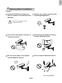
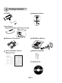
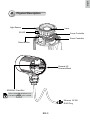
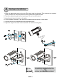
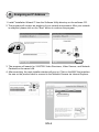
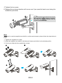
English
Warning Before Installation
Power off the Network Camera as
soon as smoke or unusual odors are
detected.
Refer to your user's manual for the
operating temperature.
Contact your distributor in the
event of occurrence.
Do not place the Network Camera on
unsteady surfaces.
Do not touch the Network Camera
during a lightning storm.
Do not insert sharp or tiny objects
into the Network Camera.
Do not drop the Network Camera.
P/N: 625016600G
EN-1
1
Package Contents
IP8362
Alignment Sticker
Sun Shield
Wrench / Double-sided Tape / Screws
Waterproof Connector
Wall Mount Bracket
Quick Installation Guide /
Warranty Card
Moisture Absorber
Software CD
EN-2
English
2
Physical Description
Light Sensor
Lens
IR LED
Focus Controller
Zoom Controller
Reset Button
General I/O
Terminal Block
SD/SDHC Card Slot
When inserting an SD/SDHC card,
note the orientation of the contacts.
Ethernet 10/100
RJ45 Plug
EN-3
3
Hardware Installation
1.Attach the alignment sticker to the wall. Drill three holes into the wall. Then hammer the supplied
plastic anchors into the holes and secure the plate with supplied screws.
2. Feed the cables through the front opening of the wall mount bracket.
3. Hang the wall mount bracket on the plate.
4. Fix the Network Camera on the wall mount bracket with two screws on both sides.
5. Secure the wall mount bracket with the supplied screws.
6. Adjust the angle of the wall mount bracket to aim at the shooting area.
1
2
3
4
6
5
The supplied L-type hex key wrenches
are exclusively designed to match each
screw. In case you will need to adjust the
lens later, do not discard the wrenches.
4
5
6
EN-4
English
4
Network Deployment
Power over Ethernet (PoE)
Using a PoE-enabled switch
The Network Camera is PoE-compliant, allowing transmission of power and data via a single
Ethernet cable. Follow the below illustration to connect the Network Camera to a PoE-enabled
switch via Ethernet cable.
Waterproof Connector
POWER
COLLISION
1
2
3
4
5
LINK
RECEIVE
PARTITION
PoE Switch
Waterproof Connection
Connect the camera's RJ45 connector through a waterproof cable gland, and to another Ethernet
cable at the installation site. Wrap the rubber seal around Ethernet cables and squeeze it into the
claws to prevent moisture. Make sure the components are tightly fastened.
RJ45 Female/Famale
Feed-through
Rubber Seal
Seal Nut
From Camera
To LAN/WAN
RJ45
EN-5
Body w/ Claws
5 Assigning an IP Address
1.Install "Installation Wizard 2" from the Software Utility directory on the software CD.
2.The program will conduct an analysis of your network environment. After your network
is analyzed, please click on the "Next" button to continue the program.
IW2
Installation
Wizard 2
3.The program will search for VIVOTEK Video Receivers, Video Servers, and Network
Cameras on the same LAN.
4.After searching, the main installer window will pop up. Click on the MAC that matches
the one on the product label to connect to the Network Camera via Internet Explorer.
Network Camera
Model No: IP8362 R o HS
MAC:0002D1730202
00-02-D1-73-02-02
This device complies with part 15 of the FCC rules. Operation is subject to the following two conditions:
(1)This device may not cause harmful interference, and
(2) this device must accept any interference received, including interference that may cause undesired operation.
Pat. 6,930,709
Made in Taiwan
192.168.5.151
0002D1730202
EN-6
IP8362
English
6
Ready to Use
1.Access the Network Camera from the LAN.
2.Retrieve live video through a web browser or recording software.
For further setup, please refer to the user's manual on the software CD.
3.Unscrew the zoom controller to adjust the
zoom factor. Upon completion, tighten the
zoom controller.
4.Unscrew the focus controller to adjust the
focus range. Upon completion, tighten the
focus controller.
N
4
T
3
∞
EN-7
W
5.Tighten the lens cover.
6.Replace the moisture absorber with a new one if you open the back cover during the
installation procedure.
6
Please tear down the aluminum foil vacuum
bag and take out the moisture absorber,
then attach the moisture absorber with the
supplied double-sided tape.
5
Note
If you want to use the supplied sun shield for outdoor environments, please follow the steps below to
install:
1. Tighten the supplied two screws.
2. Attach the supplied sun shield to the Network Camera and slide it to the desired position.
3. Fix the sun shield with the supplied two screws.
1
2
3
EN-8


![Cover [IP8362]_Outline.ai](http://vs1.manualzilla.com/store/data/006040131_1-f4c76c920c0cb23747f988387705b142-150x150.png)


![Cover [IP8151_8151P]_Outline](http://vs1.manualzilla.com/store/data/006061260_1-bb76daf44ece7d55407dbb3618e33da4-150x150.png)