1
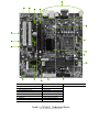
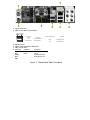
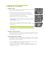
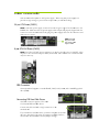
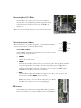
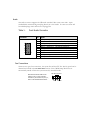
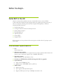
Before You Begin… Parts NOT in the Kit This kit contains all the hardware necessary to install and connect your new EVGA e-7050/610i GPU motherboard with integrated GeForce graphics processing. However, it does not contain the following items that must be purchased separately to make the motherboard fully functional. Intel microprocessor: Cooling fan and heat sink for the microprocessor System memory support Hard Disk Drive(s) Operating System Power Supply Graphics Card EVGA assumes you have purchased all necessary parts needed to allow for proper system functionality. Motherboard Specifications Size mATX form factor. Microprocessor support Intel Core 2 Extreme, Intel Core 2 Quad, Intel Core 2 Duo, Pentium EE, Pentium, and Celeron. (The e-7050/610i supports up to 1066MHz FSB CPU’s) Operating systems Supports Windows XP and Windows Vista. Contains an NVIDIA nForce MCP and integrated GeForce graphics System Memory • Single-channel DDR2 667/533 • Supports up to 4 GB DDR2 memory (2GB x 2) USB 2.0 Ports • • • Supports hot plug Up to eight (4 onboard) USB 2.0 ports Supports USB 2.0 protocol up to 480Mbps transmission rate Onboard Serial ATA II • 3Gb/s data transfer rate • Four Serial ATA II connectors • Support for RAID 0, RAID 1 • Supports hot plug and NCQ (Native Command Queuing ) Onboard LAN • LAN interfaces built-in onboard • 10/100 LAN Onboard Audio • Supports 6-channel audio • Supports Jack-Sensing function PCI Express x16 Support • Supports 4 GB/sec (8 GB/sec concurrent) bandwidth Onboard Video • Integrated video • A VGA output is provided Expansion Slots • • • Two PCI slots One PCI Express x1 slot One PCI Express x16 Graphics slot Hardware Installation This section will guide you through the installation of the motherboard. The topics covered in this section are: • Preparing the motherboard • • • Installing the CPU Installing the CPU fan Installing the memory • Installing the motherboard • Connecting cables and setting switches Safety Instructions To reduce the risk of fire, electric shock, and injury, always follows basic safety precautions. Remember to remove power from your computer by disconnecting the AC main source before removing or installing any equipment from/to the computer chassis. EVGA nForce Motherboard The EVGA nForce motherboard with the 600 series MCP processor is a PCI Express motherboard with an onboard GeForce graphics card. Figure 1 shows the 7150/630i motherboard and Figures 2 shows the back panel connectors. 15 12 12 13 14 16 17 11 1 18 10 19 10 2 3 4 8 9 7 6 1. CPU Socket 10. USB 2.0 Header 2. NVIDIA MCP with Passive Cooling 11. Front Panel Audio Head der 3. 4-Pin CPU Fan Connector 12. PCI Slots S 4. DDR2 DIMM Mem mory Slots 13. PCI-E E x1 Slot 5. FDD Connector 14. PCI-E E x16 Slot 6. 24-Pin ATX Powerr Connector 15. Backk Panel Connectors 7. IDE HDD Connecttor 16. 4-Pin n CPU Power Conne ector 8. SATA Ports 17. 3-Pin n System Fan Conn nector 9. Front Panel Heade er 18. Moth herboard CMOS Batttery 5 19. Clear CMOS Jumpe er Figure e 1. e-7010/610i Mottherboard Layout L Note: Actual motherboard m may varyy from pictures 2 1 3 4 5 5 1. PS//2 Keyboard Po ort 2. LAN N Port with LED Ds to indicate status: s Activity LED Status Off Blinking (Green) 3. 4. 5. 6. Description No data transmission n Data transmission L Status Speed/Link LED Description Gree en 100 Mbps data rate Offf 10 Mbps data rate PS//2 Mouse Port e-7 7050 Integrated d Graphics VGA A Output USB B 2.0 ports (Fo our) Aud dio Port 2-C Channel 6-Channel Gre een Lin ne-Out Front Speake er Out Pink Micc In Mic In Ora Center/Subw ange woofer Black Rear Speakerr Out ey Gre Figure 1. Chassis Back Pa anel Connecctors 6 Preparing the Motherboard Installing the CPU Be very careful when handling the CPU. Hold the processor only by the edges and do not touch the bottom of the processor. Use the following procedure to install the CPU onto the motherboard. 1. Unhook the socket lever by pushing down and away from the socket. 2. Lift the load plate. There is a protective socket cover on the load plate to protect the socket when there is no CPU installed. 3. Remove the protective socket cover from the load plate. 4. Remove the processor from its protective cover, making sure you hold it only by the edges. It is a good idea to save the cover so that whenever you remove the CPU, you have a safe place to store it. 5. Align the notches in the processor with the notches on the socket. 6. Lower the processor straight down into the socket with out tilting or sliding it into the socket Note: Make sure the CPU is fully seated and level in the socket. 7. Close the load plate over the CPU and press down while you close and engage the socket lever. Align notches with notches on the CPU Installing the CPU heat sink/fan There are many different heat sink types that can be used with this motherboard. Follow the instruction that came with your fan assembly. Be sure that the fan orientation is correct for your chassis type and your fan assembly. Installing System Memory (DIMMs) Your new motherboard has two 1.8V 240-pin slots for DDR2 memory. These slots support 256 MB, 512 MB, 1 GB, and 2 GB DDR2 technologies. There must be at least one memory bank populated to ensure normal operation. *Any of the two DIMM slots may be used as primary if only using one memory module. 1. Unlock a DIMM slot by pressing the module clips outward. 2. Align the memory module to the DIMM slot, and insert the module vertically into the DIMM slot. The plastic clips at both sides of the DIMM slot automatically lock the DIMM into the connector. Installing the Motherboard The sequence of installing the motherboard into the chassis depends on the chassis you are using and if you are replacing an existing motherboard or working with an empty chassis. Determine if it would be easier to make all the connections prior to this step or to secure the motherboard and then make all the connections. Use the following procedure to install the I/O shield and secure the motherboard into the chassis. Note: Be sure that the CPU fan assembly has enough clearance for the chassis covers to lock into place and for the expansion cards. Also make sure the CPU Fan assembly is aligned with the vents on the covers. Installing the I/O Shield The motherboard kit comes with an I/O shield that is used to block radio frequency transmissions, protects internal components from dust, foreign objects, and promotes correct airflow within the chassis. Before installing the motherboard, install the I/O shield from the inside of the chassis. Press the I/O shield into place and make sure it fits securely. If the I/O shield does not fit into the chassis, you would need to obtain the proper size from the chassis supplier. Securing the Motherboard into a System Case Most computer chassis have a base with mounting studs or spacers to allow the motherboard to be secured to the chassis and help to prevent short circuits. If there are studs that do not align with a mounting hole on the motherboard, it is recommended that you remove that stud to prevent the possibility of a short circuit. 1. 2. 3. 4. Carefully place the motherboard onto the studs/spacers located inside the chassis. Align the mounting holes with the studs/spacers. Align the connectors to the I/O shield. Ensure that the fan assembly is aligned with the chassis vents according to the fan assembly instruction. 5. Secure the motherboard with a minimum of six screws. Pow wer Con nnection ns This motheerboard requirres an ATX power supply. Make sure yo our power sup pply can provide enough wattage to power all the t componen nts you will bee installing. 24-pin ATX Pow wer (PWR1) is th he main power supply conn nector located along the edgge of the boardd next to the DIMM slots. Make sure that the poweer supply cable and pins aree properly aliggned with the wer supply cable into the co onnector and connector on the motheerboard. Firmlly plug the pow make sure it is secure. PWR1 PWR1 connecto or Plug power cable from system pow wer supply to PWR1 n ATX 12V Power P (PWR2) 8-pin PWR2, thee 4-Pin ATX 12V 1 power con nnection, is ussed to providee power to thee CPU. Align the pins to the connecto or and press firrmly until seatted. The conn nection is notcched and will o way. only fit in one FD DD Connecttor The motheerboard suppo orts a standardd 360K, 720K K, 1.2M, 1.44m m, and a 2.88M M floppy disk drive (FDD D). Co onnecting IDE Hard Diisk Drives The IDE connector c supports Ultra AT TA 133/100/666 IDE hard disk d drives. Connect th he cable end with w a single co onnector to th he motherboaard. If you instaall two hard diisk drives, youu must configuure the secondd drive as a slave s device byy setting its jumper accordin ngly. Refer to the hard diisk documentaation for the juumper settinggs. onnecting Serial S ATA Cables C Co The Serial ATA A II conneector is used to t connect thee Serial ATA II devvice to the mo otherboard. These T connecto ors support the thin Serial ATA II caables for prim mary storage deevices. The B/s data current Serrial ATA II intterface allows up to 300MB transfer ratte. There are four serial ATA co T onnectors on the t motherbo oard. These co onnectors sup pport RAID 0, RAID 1. Co onnecting Internal Hea aders Pllease refer to #9 of in the table t of Figuree 1. e-7010/6110i Motherboaard Layout for the location of th he Front Panell Headers. Front Pan nel Header The front panel p header on o this motheerboard is one connector used to connect the following fo our cables: PWRLED PWRSW HD_LE ED RESET T Attach h the front pan nel power LED D cable to thee PWR LED connector. c Th he Power LED D indicattes the system’s status. Attach h the power buutton cable fro om the case to o these two piins. Pressing th he powerbutto on on the front panel tuurns the system m on off rather than using the power sup pply button. Attach h the hard diskk drive indicattor LED cablee to these two pins. The HD DD indicator LED in ndicates the activity a status of o the hard disks. Attach h the Reset swi witch cable from m the front paanel of the casse to these tw wo pins. The system m restarts when n the RESET switch s is presssed. Note: Some chassis do not have all a four cabless. Be sure to match m the nam me on the con nnectors to th he correspondiing pins. USB B Headers The motheerboard contaiins 10-pin inteernal USB heaader connecto or(s). These can be used for a front panel USB U connectio on or USB braacket. Audio The audio connector supports the HD audio standard. Most cases come with a 10 pin standard block which will align and plug directly in to the header. In some cases there will be individual plugs which will need to be plugged in. Table 1. Front Audio Connector Connector Pin Front Audio Connector 1 PORT1_L - Analog Port 1 - left channel (Microphone) 2 AUD_GND - Ground 3 PORT1_R – Analog Port 1 – right channel (Microphone) 2 4 6 8 10 1 3 5 7 9 Signal 4 PRESENCE# - Active signal that indicates FP audio is present 5 PORT2_R – Analog Port 2 - right channel (Headphone) 6 SENSE1_RETURN – Jack detection return for front panel (Jack1) 7 SENSE_SEND – Jack detection sense line 8 Empty 9 PORT2_L – Analog port 2 – left channel (Headphone) 10 SENSE2_RETURN – Jack detection return for front panel (Jack2) Fan Connections There are two types fan connections, the system fan and the CPU fan. The fan speed can be detected and viewed in the PC Health Status section of the CMOS Setup. Both fans are automatically turned off after the system enters S3, S4 and S5 mode. Note that the CPU fan cable can be either a 3-pin or a 4-pin connector. Connect a 3-pin connector to pins 1, 2, and 3 on the motherboard connector. CPU Fan Connector 4 3 2 1 GND SENSE PWR CONTROL Expansion Slots The EVGA nForce motherboard contains four expansion slots, two PCI Express slots and two PCI slots. PCI Slots The two PCI slots support many expansion cards such as a LAN card, USB card, SCSI card and other cards that comply with PCI specifications. When installing a card into the PCI slot, be sure that it is fully seated. Secure the card’s metal bracket to the chassis back panel with the screw used to hold the blank cover. PCI Express x1 Slot There is one PCI Express x1 slot that is designed to accommodate less bandwidth-intensive cards, such as a modem or LAN card. The x1 slot provides 250 MB/sec bandwidth. PCI Express x16 Slot The PCI Express x16 slot is reserved for a graphics card. The bandwidth of the x16 slot is up to 4GB/sec (8GB/sec concurrent). When installing a PCI Express x16 card, be sure the retention clip snaps and locks the card into place. If the card is not seated properly, it could cause a short across the pins. Secure the card’s metal bracket to the chassis back panel with the screw used to hold the blank cover. Install your Operating System Boot up your machine, setup any hardware configurations within the BIOS setup if needed. Boot from your OS disk. Once your operating system is installed use the provided driver disk to install the appropriate drivers.