1
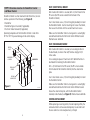
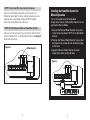
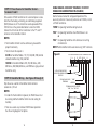
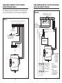
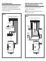
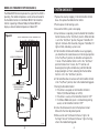
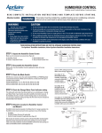
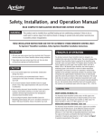
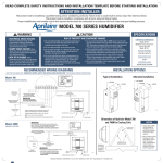
Premium
Digital Humidifier Control
Safety and Installation Instructions
READ COMPLETE INSTALLATION INSTRUCTIONS
AND TEMPLATE BEFORE STARTING INSTALLATION.
WARNING
ATTENTION INSTALLER: This product must be
installed by a qualified heating and air conditioning
contractor. Failure to do so could result in serious
injury from electrical shock.
WARNING
1. 120 volts may cause serious injury from electrical
shock. Disconnect electrical power to the HVAC
system before starting installation.
2. Sharp edges may cause serious injury from cuts.
Use care when cutting plenum openings and
handling ductwork.
CAUTION
1. Do not set humidity higher than recommended.
Condensation damage may result.
2. Do not set humidity up to recommended levels if
there is condensation on the inside of windows of
any unheated living space. Condensation damage
may result.
3. Do not mount the Humidifier Control on the supply
plenum or duct. The unit cannot withstand supply
temperatures and will malfunction.
4. When installing the Humidifier Control on a
counterflow furnace, ensure the blower continues
to run after a heat call is satisfied to eliminate high
temperatures from damaging the Humidifier Control.
TABLE OF CONTENTS
Installation . . . . . . . . . . . . . . . . . . . . . . . . . . . . . . . . . . . . . . .page 3
System Checkout . . . . . . . . . . . . . . . . . . . . . . . . . . . . . . . . .page 21
Troubleshooting . . . . . . . . . . . . . . . . . . . . . . . . . . . . . . . . . .page 22
THESE INSTALLATION INSTRUCTIONS ARE FOR THE
APRILAIRE DIGITAL HUMIDIFIER CONTROL ONLY!
For Aprilaire® humidifier installation, follow Aprilaire
Humidifier Installation Instructions.
INSTALLATION
STEP 1: Unpack the Humidifier Control Carton
Make sure all components are present (see Figure A):
A. Humidifier Control
B. Outdoor Temperature Sensor
C. Manual Mode Label
D. Manual Mode Resistor Case
A
C
5. Do not mount the Humidifier Control downstream of
the bypass outlet. False humidity conditions will
cause the humidifier to operate incorrectly.
6. Avoid installing the Humidifier Control with the display
facing downward to prevent the Humidifier Control
from incorrectly measuring the relative humidity
(RH) in the duct.
B
Figure A
2
D
90-1201
3
STEP 2: Disassemble the Humidifier Control
Figure B
Use the “OFF” setting to turn the
Water Panel Change Indicator OFF.
NOTE: When using the Model 50 Current
Sensing Relay, the Water Panel Change
Indicator MUST be OFF.
Remove the knob. Remove the cover by pulling at the bottom and
swinging it out and upward.
STEP 3: Check the Mode Switch
See Figure H (on page 12) for the mode switch (labeled A and B).
Make sure the switch is correctly set for the type of humidifier
installed.
Set the Mode Switch in position A for Models:
220, 224, 400 Series, 440, 500 Series, 550, 558,
560, 568, 600 Series, and 700 Series (gray colored
humidifiers only).
Use Setting “A”
for Model 400 Series
humidifiers in areas
with very hard water.
The indicator will light
after 150 hours of
humidifier operation.
Water Panel
Indicator
Settings
Set the Mode Switch in position B for Models:
110, 112, 445, 448, 700 (almond colored humidifier
only), 760, and 768.
Use Setting “B”
for Model 400 Series,
500 Series, 600 Series
and 700 Series
humidifiers in areas
with very hard water.
The indicator will light
after 300 hours of
humidifier operation.
Do not operate the humidifier with the Mode Switch in the
wrong position. Damage to the Humidifier Control could result.
STEP 4: Check the Change Water Panel indicator setting.
This setting will control when the indicator light turns on,
reminding you to change your water panel. If your Control came
with a humidifier, the Control is pre-set for the humidifier. If the
installation site has a 3-month or shorter heating season or very
hard water, you may want to adjust the setting (see Figure B).
Use Setting “C” for Model 500 Series, 600 Series
and 700 Series humidifiers. The indicator will light
after 600 hours of humidifier operation.
90-1202
4
5
DUCT (SHEET METAL) MOUNT:
STEP 5: Determine Location for Humidifier Control
and Mount Control
Humidifier Control must be mounted on the Return Duct, at least
6 inches upstream of the following (see Figure C):
After location for Control is selected, drill a 3/4 inch hole for the
RH sensor (the RH sensor extends from the back of the
Humidifier Control).
• Humidifier
• Humidifier Bypass Ductwork (if applicable)
• Fresh Air Intake Ductwork (if applicable)
Use 2 sheet metal screws, 3/4 inch long (not provided), to mount
the Humidifier Control. Use the mounting slot to level the Control,
then secure the Control with the second sheet metal screw.
Operating temperature of the Humidifier Control is to be from
20°F to 120°F to prevent damage to the control display.
Make sure the Humidifier Control sensor gasket is seated tightly
around the drilled hole. Do Not Install Control Without Gasket.
Reattach cover and knob.
DUCT (FIBER BOARD) MOUNT:
RETURN
DUCT
After location for Control is selected, cut a rectangular hole in
the duct board, no smaller than 6-9/16 inches long by 4-3/8
inches wide.
6" MIN.
HUMIDIFIER
CONTROL
FRESH AIR
INTAKE
HUMIDIFIER
Cut a rectangular piece of sheet metal to fit behind the hole in
duct board for mounting the Humidifier Control.
COIL
Drill a 3/4 inch hole for the RH sensor (the RH sensor extends
from the back of the Humidifier Control) into the sheet metal
plate.
Use 2 sheet metal screws, 3/4 inch long (not provided), to mount
the Humidifier Control.
BYPASS
CONNECTION
Figure C
90-1137
Make sure the Humidifier Control sensor gasket is seated tightly
around the drilled hole. Do Not Install Control Without Gasket.
Secure the sheet metal plate, with the Humidifier Control
mounted, inside the duct (see Figure D). Reattach cover and knob.
CONTROL REPLACEMENT:
When replacing an existing control, the duct opening left by the
removed control must be covered completely. Locate and install
the new control as instructed previously in Step 5.
6
7
Figure D – Fiber Board Duct Mount
Figure E – Digital Humidifier Control 24V Terminals
CONTROL BOARD
COVER
GASKET
SCREW (x2)
R
KNOB
C
A
B
ODT
W/G Cf
H
INSIDE OF
RETURN
DUCT
OUTDOOR
TEMPERATURE
SENSOR OR
MANUAL MODE
RESISTOR
BASE PLATE
SHEET METAL PLATE
RETURN DUCT
RETURN
DUCT
CUT OPENING IN
RETURN DUCT
SHEET METAL
PLATE
24V BLOWER
OPERATION SIGNAL
FROM HVAC
EQUIPMENT
FOR
COMMUNICATION
WITH APRILAIRE
8570 THERMOSTAT
CONTINUOUS 24V
POWER FOR CONTROL
24V SIGNAL TO
HUMIDIFIER
90-1203
8
90-1397
9
STEP 6: Determine Location for Outdoor
Temperature Sensor
STEP 8: Alternate Location for Outdoor
Temperature Sensor
The location of the Outdoor Temperature Sensor must meet
these three requirements:
The Sensor can also be mounted in the center of either:
• PVC fresh air intake pipe for the HVAC system
1. Must be mounted on North, East or West side of house out of
direct sunlight
2. Must be at least 3 feet from all exhaust vents
3. Must be above expected snow line (see Figure F)
Incorrect humidity levels will result if these requirements are not
met.
Figure F
NORTH, EAST
OR WEST SIDE
OF HOME
OUTDOOR
TEMPERATURE
SENSOR
OR
• fresh air intake duct. Mount the sensor with a #8 galvanized
screw.
In both cases, the Sensor must be no more than 3 feet
from the outside wall. See Figure G.
If it is not feasible to use the Outdoor Temperature Sensor in any
of the ways described, the Humidifier Control can be installed for
Manual Operation. See “Installing the Humidifier Control for
Manual Operation” and Figure J on page 13 for details.
Figure G
SENSOR
SENSOR
BRACKET
OUTDOOR
TEMPERATURE SENSOR
LEADS
CENTER LINE
ABOVE EXPECTED
SNOW LINE
90-998
3 FEET MAX.
STEP 7: Locate Existing Access Hole to Outside
OUTSIDE WALL
A convenient way to get the Sensor wire outside is to make use
of unused wires running to the A/C condensing unit (if
applicable). Other ways are to use existing holes for Cable TV
lines, telephone lines, A/C lines, etc. Read all equipment
instructions beforehand for possible conflicts and warnings.
10
90-999
11
STEP 9: Route the Wire from Control to Sensor
Run wire to the outdoor temperature sensor. Sensor is not
affected by lead length. Do not run outdoor temperature sensor
alongside wires carrying high voltage (120 VAC or higher).
Secure the sensor bracket with a #8 screw.
STEP 10: Attach Sensor Wire to Humidifier Control
Strip wire 1/4 inch, and insert the wires from the Sensor into the
terminals labeled “ODT” on the Humidifier Control. See Figure H
for location of terminals.
Figure H
Mode Switch
Installing the Humidifier Control for
Manual Operation
If it is not feasible to install the Outdoor
Temperature Sensor, the Humidifier Control can be
operated in Manual Mode.
1. Connect the Manual Mode Resistor Case wires
to the terminals labeled “ODT” on the Humidifier
Control.
2. Position the Manual Mode Resistor Case so that
the Resistor Case extends from the bottom edge
of the base.
3. Apply the Manual Mode label to the cover,
aligning the sticker and knob holes.
Figure J
R
C
A
B
ODT
W/G Cf
H
R
C
A
B
ODT
W/G Cf
H
90-1219
90-1220
12
13
STEP 11: Power Source for Humidifier Control –
Terminals R and C
Wire external 24 VAC transformer into a constant power source
other than the heating, ventilating, air conditioning equipment
(HVAC) blower circuit. The transformer can be powered off the
120 VAC line at the junction box before it enters the HVAC.
Connect the 24 volt side of the transformer to the “R” and “C”
terminals on the Humidifier Control.
NOTES:
• The Humidifier Control must be continuously powered for
proper functionality.
USING FURNACE ACCESSORY TERMINALS TO DETECT
FURNACE OR BLOWER OPERATION (FIGURE K)
See the furnace manual for voltage and operation of the
accessory terminals. If accessory terminals are 120 Volts, install
a 24 VAC transformer.
“HUM” for operating humidifier during heat call.
“EAC” for operating humidifier when HVAC blower is on.
or
“EAC” for operating humidifier with continuous fan setting
on thermostat.
NOTE: Plumb humidifier to hot water when using “EAC” terminals.
• The minimum VA required is:
2.0 VA for humidifier Models 110, 112, 445, 448, 700 (almond
colored humidifier only), 760, and 768.
10.0 VA for humidifier Models 220, 224, 400 Series, 440,
500 Series, 550, 558, 600 Series, and 700 Series (gray colored
humidifiers only).
STEP 12: Humidifier Wiring – See Figures K through Q
Strip the wires used for all Humidifier Control terminal
connections 1/4 inch.
Figure K
DIGITAL HUMIDIFIER CONTROL TERMINAL STRIP
R C A B ODT W/G Cf
H
24 VAC TRANSFORMER
OUTDOOR TEMPERATURE
SENSOR OR MANUAL MODE
RESISTOR
FURNACE ACCESSORY “HUM”
TERMINALS
COMMON
TERMINALS MAY BE LABELED:
“HUM”, “ACC” OR “EAC”
NOTES:
• In order for the humidifier to operate, the HVAC blower must
be running and the Humidifier Control must be calling for
humidity.
• There are several ways to detect HVAC blower operation.
See the wiring diagrams for options.
90-1221
14
15
USING FURNACE TERMINALS TO DETECT FURNACE
BLOWER OPERATION (FIGURE L)
USING HUMIDIFIER CONTROL TO ACTIVATE HVAC BLOWER
ON CALL FOR HUMIDITY (FIGURE M)
This configuration allows the humidifier to run only during heat
call, even if the thermostat is set for continuous fan operation.
Figure M
R
C
MODE SWITCH IN “A” POSITION
DIGITAL HUMIDIFIER CONTROL
ODT
W/G Cf
A
B
H
Figure L
DIGITAL HUMIDIFIER CONTROL TERMINAL STRIP
H
R C A B ODT W/G Cf
OUTDOOR
TEMPERATURE
SENSOR
10VA
TRANSFORMER
PROVIDED WITH
HUMIDIFIER
OUTDOOR TEMPERATURE
SENSOR OR MANUAL
MODE RESISTOR
WHITE/YELLOW
WHITE/BLUE
YELLOW (C)
ORANGE (NO)
BLUE (NC)
24 VAC
TRANSFORMER
4851 RELAY
APRILAIRE
R
Y
COMMON
G
W
FURNACE
TERMINAL
STRIP
500 & 600 SERIES
YELLOW WIRES
400 SERIES
YELLOW WIRE &
WHITE WIRE
700 SERIES
BROWN WIRES
R
C
W
G
Y
TYPICAL 24 VAC
TERMINAL STRIP
IN FURNACE
REMOVE WIRE
“G” TO “G”
R
C
W
G
Y
THERMOSTAT
90-1223
16
NOTE:
18 AWG WIRE IS
ACCEPTABLE FOR 24V
INSTALLATIONS.
NOTE:
PLUMB HUMIDIFIER
TO HOT WATER WHEN
USING THIS WIRING
CONFIGURATION.
90-1398
17
HEAT PUMP WIRING (FIGURE N)
This configuration allows the humidifier to run whenever the
heat pump blower is running (and the Humidifier Control is
calling for humidity). The humidifier solenoid should be plumbed
to hot water for this option.
USING MODEL 50 CURRENT SENSING RELAY TO DETECT
FURNACE BLOWER OPERATION (FIGURE P)
This option is to be used only if the furnace terminals or
accessory terminals are not used.
NOTE: The Water Panel Change Indicator must be set to the
“OFF” position for this option.
Figure N
Figure P
DIGITAL HUMIDIFIER CONTROL TERMINAL STRIP
R C A B ODT W/G Cf
H
DIGITAL HUMIDIFIER CONTROL TERMINAL STRIP
R C A B ODT W/G Cf
H
24 VAC
TRANSFORMER
24 VAC
TRANSFORMER
OUTDOOR TEMPERATURE
SENSOR OR MANUAL
MODE RESISTOR
FURNACE
BLOWER
COMMON
R
Y
G
W
B or O
HEAT PUMP
TERMINAL
STRIP
OUTDOOR TEMPERATURE
SENSOR OR MANUAL
MODE RESISTOR
COMMON
MODEL 50
90-1225
18
90-1222
19
MODEL 8570 THERMOSTAT OPTION (FIGURE Q)
SYSTEM CHECKOUT
The Model 8570 Thermostat provides the signal that the HVAC is
operating. The outdoor temperature sensor can be connected to
the Humidifier Control or to the Model 8570. If the Humidifier
Control is operating in Manual Mode, the Model 8570 will
display a constant outdoor temperature of about 20°F.
Figure Q
DIGITAL HUMIDIFIER CONTROL TERMINAL STRIP
R C A B ODT W/G Cf
H
24 VAC
TRANSFORMER
MODEL 8570 THERMOSTAT
ZA
ZB
(SEE INSTRUCTIONS)
OUTDOOR TEMPERATURE
SENSOR OR MANUAL
MODE RESISTOR
90-1226
20
1. Replace the cover by snapping it into the Humidifier Control
base. Also replace the knob onto the Control.
2. Restore power to the heating system.
3. Activate the HVAC system or heat pump.
4. Once the blower is operating, rotate the knob of the Humidifier
Control Clockwise to the “Test/Reset” position. When the knob
is set in the “Test/Reset” position, the green “Humidifier On”
light will illuminate. After 5 seconds, the green “Humidifier On”
light will blink, indicating a system reset.
5. If the Humidifier Control and humidifier are set up properly,
you should hear the solenoid valve click into the open position.
In the “Test/Reset” position, the humidifier will operate for
1 minute. If the Humidifier Control is left in the “Test/Reset”
position for more than 1 minute, the “H” terminals will
de-energize (closing the solenoid valve), and the knob and
display backlights will flash, indicating that the Humidifier
Control is still in the “Test/Reset” position.
6. If the humidifier does not activate with the Humidifier Control
in the “Test/Reset” position, refer to the troubleshooting guide.
7. Setting the Humidifier Control:
• If the home is occupied, set the Humidifier Control to
“Normal” (For Manual Mode, set to 35%)
• If the home is vacant, set the Humidifier Control to “OFF”
• If in Manual Mode and system is installed during cooling
season, set the Humidifier Control to “OFF”
8. Instruct the homeowner to refer to the Aprilaire Owner’s
Manual for the initial adjustment period.
9. Make sure the red “Call Dealer for Service” light is not
flashing. If the red “Call Dealer for Service” light is flashing,
refer to the troubleshooting guide.
21
TROUBLESHOOTING
TROUBLESHOOTING PROCEDURE (CONTINUED)
Applies to both Automatic and Manual Operation unless
indicated otherwise.
SYMPTOM
Call Dealer For Service Light Flashing (see Figure R)
TROUBLESHOOTING PROCEDURE
Display Error Code: E1: RH Sensor
Rotate Humidifier Control knob to the “Test/Reset” position. After
5 seconds, the green “Humidifier On” light will blink, resetting
the error. If E1 returns, replace the Humidifier Control.
Display Error Code: E2: Control Knob
Rotate Humidifier Control knob to the “Test/Reset” position. After
5 seconds, the green “Humidifier On” light will blink, resetting
the error. If E2 returns, replace the Humidifier Control.
Display Error Code: E3: Outdoor Temperature Sensor
1. Make sure that the Outdoor Temperature Sensor is properly
connected to the ODT terminals on the Humidifier Control.
2. Measure the resistance of the Outdoor Temperature Sensor
by removing the leads from the Humidifier Control terminals
and measuring the resistance across the wires with an
ohmmeter. Confirm the reading with the temperature in
Table 1. (For Manual Operation, verify that the resistance
across the leads of the Manual Mode Resistor Case is
between 44K and 48K ohms). Reconnect the ODT leads. If
the resistance value does not match the temperature value,
replace the Outdoor Temperature Sensor.
3. Rotate Humidifier Control knob to the “Test/Reset” position.
After 5 seconds, the green “Humidifier On” light will blink,
resetting the error. If E3 returns, replace the Humidifier Control.
22
Display Error Code: E4: Communication
This only applies to systems wired to an Aprilaire Model 8570
Thermostat (see Figure Q).
Rotate the Humidifier Control knob to the “Test/Reset” position.
After 5 seconds, the green “Humidifier On” light will blink,
resetting the error. If E4 returns, check the wiring between the
Digital Humidifier Control and Model 8570. Make sure the
Model 8570 is wired and operating properly according to the
Model 8570 manual.
TABLE 1
Outdoor Temperature (°F)
Resistance (kΩ) ±10
-30
-20
-10
0
10
20
30
40
50
60
70
80
90
100
231.8
163.4
117.3
84.8
62.2
46.1
34.4
26.1
19.9
15.3
11.9
9.3
7.3
5.8
Figure R
Red “Call Dealer For Service” Light
Yellow “Change Water Panel” Light
Green “Humidifier On” Light
90-1227
23
SYMPTOM
Humidifier does not operate in “Test/Reset” mode
TROUBLESHOOTING PROCEDURE
• Make sure that the blower is operating and the HVAC
system is calling for heat.
• Check wiring diagrams for correct Humidifier Control
installation.
• If connected to a Model 400 Series humidifier, make sure
both floats in the bottom of the scale control insert are in
the down position. If necessary, dump out water to lower
the floats.
SYMPTOM
Yellow “Change Water Panel” Light is blinking (see Figure R)
TROUBLESHOOTING PROCEDURE
Check the condition of the Water Panel and replace it if
mineral deposits are blocking air flow. Follow the instructions
on the Water Panel box. Rotate the knob to the “Test/Reset”
position for at least 5 seconds to reset Water Panel change
timer. Check that the timer setting is correct for the humidifier
model and water conditions (see Figure B). DO NOT LEAVE
THE HUMIDIFIER CONTROL IN “TEST/RESET” MODE AS THE
HUMIDIFIER WILL NOT OPERATE.
• Check voltage at the Humidifier Control “R” and “C”
terminals. Voltage should be 22 VAC minimum to 30 VAC
maximum.
• Check the Model 50 Current Sensing Relay (if used) for the
correct installation (see Model 50 instructions).
• Check Blower Activation Relay Model 4851 (if used) for
correct installation (see Model 4851 instructions).
• Make sure that the saddle valve is open.
• In “Test/Reset mode, the humidifier will operate for
1 minute only. DO NOT LEAVE THE HUMIDIFIER CONTROL
IN “TEST/RESET” MODE AS THE HUMIDIFIER WILL NOT
OPERATE.
24
25
SYMPTOM
SYMPTOM
Humidifier operates only in “Test/Reset” mode
Humidifier operates constantly
• If outdoor temperature is greater than 60°F or less than
-30°F, the Humidifier Control will only operate in the
“Test/Reset” mode (for 1 minute).
• If the humidity level in the home is less than the Humidifier
Control knob setting and there is a continuous fan call or
heat call (depending on setup), the Humidifier Control will
operate the humidifier until the humidity level is higher than
the Humidifier Control knob setting.
• If the humidity level in the home is higher than the
Humidifier Control knob setting, the Humidifier Control will
not operate the humidifier.
TROUBLESHOOTING PROCEDURE
• Measure the resistance of the Outdoor Temperature Sensor
by removing the leads from the Humidifier Control terminals
and measuring the resistance across the wires with an
ohmmeter. Confirm the reading with the temperature in
Table 1. (For Manual Operation, verify that the resistance
across the leads of the Manual Mode Resistor Case is
between 44K and 48K ohms). Reconnect the ODT leads.
If the resistance value does not match the temperature
value, replace the Outdoor Temperature Sensor.
• Make sure that the Outdoor Temperature Sensor is mounted
completely outside the house on the North, East or West
side of the house and out of direct sunlight. (Automatic
Mode Only)
TROUBLESHOOTING PROCEDURE
• In the “Test/Reset” mode, verify that the humidifier turns
off after 1 minute.
• Check the Outdoor Temperature Sensor resistance and
location, as instructed on the previous page.
• Rotate the Humidifier Control knob counterclockwise to the
“Off” position, and observe whether the humidifier turns
off. If the humidifier still operates in the “Off” position,
perform the following:
1. Check the wiring diagram for correct Humidifier Control
Installation.
2. Remove the wires from the “H” terminals on the
Humidifier Control. If the humidifier continues to operate,
replace the solenoid valve.
• Make sure that the Outdoor Temperature Sensor is located
at least 3 feet away from all exhaust vents. (Automatic
Mode Only)
• If Outdoor Temperature Sensor is mounted in the fresh
air intake duct, make sure that the sensor is no more than
3 feet from the outside wall. (Automatic Mode Only)
26
27
SYMPTOM
Humidifier or Humidifier Control “chatters” or clicks On and
Off rapidly
TROUBLESHOOTING PROCEDURE
• Check for steady 22 VAC to 30 VAC across the “R” and “C”
terminals of the Humidifier Control with a voltmeter.
• Check, with a voltmeter, that the HVAC signal across the
“W/G” and “Cf” terminals of the Humidifier Control is a
steady 22 VAC to 30 VAC.
• Make sure that the Outdoor Temperature Sensor wiring is
not running alongside other wires carrying high voltage
(120 VAC or higher). (Automatic Mode Only)
RESEARCH PRODUCTS CORPORATION
P.O. BOX 1467 • MADISON,WI 53701-1467
Call 800/334-6011 • FAX 608/257-4357
10008419 1.09
B2204686B
28