1
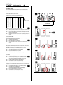
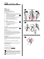
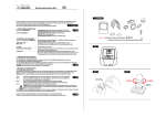
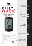
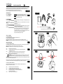
CYCLECOMPUTING
Instruction manual A4+
GB
Congratulations on your purchase of a VDO Cycle Computer. To enjoy the full potential of your computer and benefit from all the technical
features, we recommend you thoroughly study this manual. You will find crucial hints for its operation as well as many more tips.
We wish you many enjoyable rides and trips on your bike with your VDO cycle computer.
Contents
Please check the packaging before starting the installation to ensure the contents are complete.
F
1. Button Function
RIGHT BUTTON (MODE-Button)
LEFT BUTTON (SET-Button)
In Cycling Mode: Use this button to progress through the ODO, TRP, CLK screens.
In SET-Mode: Use this key to adjust values within the Set-up screen
Use this button to access the set-up screens for Wheelsize, Clock and Odometer.
In SET-Mode: Selection of digit to be changed
F
F Contents
P01
2. Computer-Functions
ACTUAL SPEED (KMH/MPH)Actual Speed is permanently shown on the display, up to 120 KMH (75 MPH) with an accuracy of 0.1 digits.
TRIP DISTANCE (TRP)Shows Trip Distance of actual ride, up to 999. 99 KM or M. At overflow of 999.99 counting
(TRP = TRIP)
re-starts at 000.00.
CLOCK (CLK)
Shows actual time in 24-hour-format.
TOTAL DISTANCE ODOMETER (ODO)
Shows accumulated Total Trip Distance data of all individual trips. Counts up to 99999 KM or M. Value is re-settable after change of battery.
SLEEP MODETo prolong battery life, the A4+ will automatically enter „sleep“ mode after 3 minutes of
non-use. Only the Clock is shown.The wireless receiver of A4+ will stay ON for another 3
hours to allow Auto-Start/Stop. In case of non-use, the receiver will be switched OFF.
This is indicated by a flashing “CLK”. To re-start the computer press any button In continu
ed non-use, the receiver is switched OFF latest at midnight 24:00.
The computer will restart when any button is pressed.
*Watch out: old batteries require special disposal
Please read instructions for end-off-life disposal treatment
P02
P01
3. Reset of computer
3.1 RESET OF ACTUAL TRIP DATA
To Reset actual trip data TRP press SET plus MODE-button simultaneously for 3 sec.
3.2 RESET OF COMPUTER TO FACTORY-SETTINGS
To Reset the computer to default factory settings, use a pencil and press the “AC”-button on underside of the computer.
ATTENTION: This action will delete all your data and all your settings for wheelsize, clock, odometer will be reset to factory settings.
AC-button
F
P02
4. Mounting and Settings
4.1 INSTALLATION OF BATTERY IN COMPUTER
To prolong battery life, the A4+ will come without the battery being installed. The VDO A4+ needs a battery 3V-Type CR 2032. Batteries are
available at your dealer (VDO-part no.#1013). Battery life time is around 12 months at normal use.
Watch Out: In case of malfunction please check the battery first before you start a warranty complaint.
SET
MODE
F
STEP 1
Remove the battery door with a suitable coin
P03
STEP 2Place the battery in the battery chamber. PLUS+-pole visible. Be careful when installing the battery
not to damage the battery contact.
STEP 33 Reinstall the battery cap, making sure that the rubber O-ring does not get pinched or distorted.
WATCH OUT: If O-ring gets pinched or distorted, this will compromise the unit’s watertight seal.
STEP 4Tighten the battery door firmly with a suitable coin.
IMPORTANT: During battery replacement all data and all settings will be stored for around 20 Seconds. To save your data,
replace the battery within that 20 seconds, otherwise all settings for Wheelsize, Clock and Odometer need to be re-done.
Tip: Buy replacement battery in time. To save your data and settings replace the battery in time. Before replacing the battery we recommend
to take note of your Wheelsize Setting and Odometer-data.
P03
P04
!
Watch Out: If for some reason the screen is blank or shows an irregular display after a battery change, press the AC button on the backside of
the computer. This action will delete all data and all settings and requires new settings of Wheelsize, Clock and Odometer.
P02
F
4.2 INSTALLATION OF BATTERY IN TRANSMITTER
The VDO A4+ transmitter needs a battery 12V-Type LR 23. Batteries are available at your dealer (VDO-part no.#1014).
Battery life time is around 12 months at normal use.
STEP 1
Remove the battery door of transmitter with a suitable coin.
STEP 2Place the battery in the battery chamber. PLUS+-pole visible.
Be careful when installing the battery not to damage the battery contact.
STEP 3Reinstall the battery cap. Watch Out: If O-ring gets pinched or distorted this will
compromise the unit’s watertight seal.
STEP 4
Tighten the battery door firmly with a suitable coin.
F P04
OPEN
OPEN
CLOSE
Battery
CLOSE
CYCLECOMPUTING
Instruction manual A4+
GB
5. Programming of computer
To show Speed and calculate Trip Distance and the other data, your VDO A4+ needs the precise wheelsize = wheel circumference
(in mm or inch) of your bike.
5.1 HOW TO DETERMINE YOUR WHEELSIZE:
The wheelsize setting can be done with an accuracy of 1 mm or 0.1 inch.
The table below shows the most common tire sizes and the related wheelsize-data in mm and inch.
This data not necessarily corresponds with the correct data of your bike.
Tire size
47-305
47-406
34-540
47-507
23-571
40-559
44-559
47-559
50-559
n/a
54-559
n/a
57-559
37-590
16x1,75
20x1,75
24x1 3/8
24x1,75
26x1
26x1,5
26x1,6
26x1,75
26x1,9
26 x 1,95
26x2,00
26 x 2,1
26x2,125
26x1 3/8
WS in mm KMH WS in inch MPH
1272
50,1
1590
62,6
1948
76,7
1907
75,1
1973
77,7
2026
79,8
2051
80,7
2055
80,9
2060
81,1
2070
81,5
2075
81,7
2080
81,9
2133
84,0
2105
82,9
Tire size
20-571
32-630
40-622
47-622
40-635
37-622
18-622
20-622
23-622
25-622
28-622
32-622
37-622
40-622
26x3/4
27x1 1/4
28x1,5
28x1,75
28x1 1/2
28x1 3/8
700x18C
700x20C
700x23C
700x25C
700x28C
700x32C
700x37C
700x40C
WS in mm KMH WS in inch MPH
1954
76,9
2199
86,6
2224
87,6
2268
89,3
2265
89,2
2205
86,8
2102
82,8
2114
83,2
2133
84,0
2146
84,5
2149
84,6
2174
85,6
2205
86,8
2224
87,6
P05
!
1x
MINIMUM WS: 100 mm / 3,94“
MAXIMUM WS: 3999 mm / 157,44“
WS in mm / inch
F
P05
If your Tyre Size is not shown in the Table, you can find your correct wheelsize as explained below:
STEP 1Stand your bicycle upright. With your tyre inflated to its proper pressure, rotate your front wheel so that the valve is located
at the bottom (6 o’clock position). Make a mark on the floor to indicate the valve location.
STEP 2Roll the bicycle forward in a straight line for one complete wheel revolution, until the valve is again at the bottom. Make a
mark on the floor to indicate this valve location.
STEP 3Measure the distance between the marks in millimetres or inches (1 inch = 25.4mm). This value is your wheel size = wheel
circumference.
5.2 SELECTION OF KMH OR MPH-READING
The VDO A4+ can show speed and all related data either in km or m. You can switch at any time from km to m-reading
and vice versa. All data TRP, AVS, MXS, ODO will automatically be re-calculated.
STEP 1
Get TRP in display, press and hold SET-button for 3 sec.
km or m are flashing. Use MODE-button to select km or m-reading.
STEP 2
STEP 3Press SET-button to confirm above selection. The A4+ will now show the set-mode for the wheelsize = wheel
circumference.
P07
P07
F P06
5.3 PROGRAMMING THE WHEELSIZE
After pressing SET-button to confirm km or m selection, the A4+ will now show the set-mode for the wheelsize = wheel circumference.
Factory settings for wheelsize are 2155 mm for km-reading and 84, 8 inch for m-reading.
Attention: For km-reading the wheelsize needs to be set in mm, for m-reading the wheelsize needs to be set in inches.
STEP 1
Change the flashing wheelsize-digit to requested value by pressing the MODE-button.
P07
STEP 2
Press SET-button to confirm this setting and move to next digit.
STEP 3
Repeat Step 1 and Step 2 until all digits have been set to your wheelsize.
STEP 4
Press and Hold SET-button for 3 sec. to finish Wheelsize-Setting and return to TRP-display.
F
5.4 CLOCK SETTING
Your VDO A4+ shows actual time in 24:00 (hh:mm) format.
STEP 1Get CLK into display. Press and Hold SET-button for 3 sec. The Clock SET-Mode will be shown in display.
STEP 2
Use the MODE-button to change the flashing hour-digits. Hold MODE-button for fast setting.
Confirm your settings by pressing the SET-button. This confirmation will also change to Minute-setting.
STEP 3
Use the MODE-button to change the flashing Minute- digits. Hold MODE-button for fast setting.
STEP 4Press and hold SET-button for 3 sec. to finish Clock-Setting and return to CLK-display.
P06
P08
F P08
5.5 PROGRAMMING OF ODOMETER
The total distance counter ODO can be programmed anytime, for example after a change of battery or to enter the ODO data of your old
computer into your new A4+.
STEP 1
Get ODO into display, press and Hold SET-button for 3 sec. The ODO-Set-Mode will be shown in display.
P09
STEP 2
Press MODE-button to change the flashing digit to requested value.
Confirm this setting by pressing the SET-button and simultaneously change to next digit (flashing).
STEP 3
Repeat STEP 1 and STEP 2 until all digits have been set to requested value.
STEP 4Press and Hold SET-button for 3 sec. to finish ODO-setting and return to ODO-display.
F
P09
CYCLECOMPUTING
Instruction manual A4+
GB
6. Mounting
6.1 MOUNTING OF MAGNET AND TRANSMITTER
Important! Watch Out when mounting!
The distance between Transmitter and magnet should be 1 to 3 mm.
The distance between Transmitter and Computer should not be larger than 75 cm (30”).
Tip: With Linear Pull/Cantilever-Brakes do not mount the transmitter too close to the brakes.
Distance to the brake should be 10 cm (4”).
STEP 1Loosely mount Transmitter on the front fork using the zip ties, so that you can still make final adjustments. Mounting on right
or left side of the fork is possible.On the right-side mounting, the battery door of the transmitter will point downwards, so that
the Sensor-marking on the transmitter will point towards the magnet in the spokes.
P10
STEP 2Loosely mount the magnet at the spoke, so that you still can do final adjustments.
The magnet must point towards the sensor-marking on the Transmitter.
STEP 3
Make final adjustments of the magnet towards the Sensor-marking, ensure the distance between the magnet and the sensor marking is 1 to 3 mm. To get that distance also adjust the Transmitter towards the magnet.
STEP 4
To finally fix the Transmitter. Pull zip-ties tight. Cut off remaining zip-tie-parts.
STEP 5
To finally fix the magnet. Press the magnet-shell until the magnet is securely fixed at the spoke.
P10
right side mounting
left side mounting
F
6.2 MOUNTING OF BRACKET
STEP 1
Decide if you want to mount the bracket on handlebar or on stem.
STEP 2Depending on your decision you may need to turn the foot of the bracket by 90 °.
Remove the 2 screws, turn the foot of the bracket to adjust for either handlebar or stem-mounting.
STEP 3
Fix the foot of the bracket with the 2 screws. Do not overstress the screws.
STEP 4Fix the bracket to either the handlebar or the stem by using 2 zip-ties.
Cut off the remaining zip-tie-parts.
F P11
1-5mm
1-5mm
P11
90°
6.3 HEAD UNIT INSTALLATION
Place the computer into the bracket ( 10-o’clock-position) and turn clockwise until you feel a click and have reached 12 o’clock position.
Watch Out: Make sure the computer is properly placed into the bracket and is turned clockwise until you feel the “Click”.
P12
To remove the computer off the bracket, twist the head counter-clockwise and then lift it out of the bracket.
F
7. Test of Function
After installation, please check function of your VDO A4+.
Lift the front wheel of your bike. Turn the front wheel. Within 2 to 4 seconds a speed reading should be in display of your VDO A4+.
Otherwise re-check the magnet position and the distance of the magnet towards the Sensor-marking. Re-adjust the position and distance
and check again.Re-check the distance between Transmitter and Computer. This distance should be no larger than 75 cm (30”). Should the
distance be larger, you need to move the transmitter upwards on the fork and re-mount in a closer position towards the Computer.
We wish you many enjoyable rides and trips on your bike with your VDO A4+ cycle computer.
In case of any technical problems contact your dealer.
8. Warranty disclaimer
VDO Cycle Parts warrants your VDO-Computer for 5 years from date of purchase. This warranty covers defects in material and workmanship.
Defects on cables, senders, transmitters and mounting materials resulting from normal wear and tear, improper care, accidents, abuse or
alteration are not covered by our warranty. Opening the computer housing (except for the battery door) is considered abuse, thus not covered
by our 5 year warranty.
Please keep your sales receipt to prove that your computer is covered under the warranty in case of legitimate complaints.
In case of legitimate complaints you are entitled to have your computer either repaired or replaced with a comparable model. Due t possible
model changes, your model might have been discontinued.
In the event that you should have a complaint, please first contact the retailer where you purchased your VDO computer. If the retailer is
unable to help, you can return your computer to:
Cycle Parts GmbH, Große Ahlmühle 33, D-76865 Rohrbach.
In case of technical queries, please contact our customer-service-hotline: +49-6349-9635-10.
Further technical information is available on our website: http://www.vdocyclecomputing.com
Technical specifications of our computers are subject to change without notice.
Instructions for end-of-life disposal treatment
This product complies with EU Directive 2002/96/EC. The symbol * on the product or on its packaging indicates that this
product may not be treated as household waste. Instead it shall be handed over to the applicable collection point for the recycling of electrical and electronic equipment. By ensuring this product is disposed of correctly, you will help prevent potential
negative consequences for the environment and human health, which could otherwise be caused by inappropriate waste
handling of this product. For more detailed information about recycling of this product, please contact your local city office,
your household waste disposal service or the shop where you purchased the product.
P12
OPEN
CLOSE