1
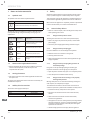
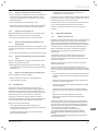
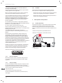
Installation instructions
For the competent person
Installation instructions
VR 66 Control Centre
VR 66
GB, IE
TABLE OF CONTENTS
1
Notes on the documentation ......................................................................................................... 2
1.1
1.2
1.3
1.4
2
Safety.......................................................................................................................................... 2
2.1
2.2
2.3
2.4
3
Product Overview ................................................................................................................4
Product structure ................................................................................................................5
Type designation and serial number ...................................................................................11
Data plate description .......................................................................................................11
Mounting and installation ........................................................................................................... 11
4.1
4.2
4.3
5
General safety advices.........................................................................................................2
Intended use.......................................................................................................................3
Rules and regulations ..........................................................................................................3
CE label ..............................................................................................................................4
Description of the product ............................................................................................................ 4
3.1
3.2
3.3
3.4
4
Symbols used .....................................................................................................................2
Observe other applicable documents ...................................................................................2
Storing documents ..............................................................................................................2
Validity of the instructions ...................................................................................................2
Preparing the mounting and installation .............................................................................11
Mounting the product ........................................................................................................11
Electrical Installation .........................................................................................................12
Commissioning .......................................................................................................................... 13
5.1
5.2
5.3
5.4
5.5
Filling ...............................................................................................................................13
Venting ............................................................................................................................13
Switching on.....................................................................................................................13
Multizone specific adjustment ...........................................................................................13
Restart and check..............................................................................................................13
6
User information ........................................................................................................................ 14
7
Maintenance .............................................................................................................................. 14
7.1
7.2
Trouble-shooting...............................................................................................................14
Main supply cable .............................................................................................................14
8
Decommissioning ...................................................................................................................... 15
9
Recycling and disposal ............................................................................................................... 15
9.1
9.2
10
Guarantee and customer service ................................................................................................. 15
10.1
10.2
11
Recycle the packaging .......................................................................................................15
WEEE: Recycle or dispose the product and its components ...................................................15
Vaillant warranty ...............................................................................................................15
Vaillant Service .................................................................................................................15
Technical data ............................................................................................................................ 15
EN
-1-
INTRODUCTION
1
Notes on the documentation
1.1
The symbols used in the text are explained below:
Explanation
i
∙
Symbol that denotes useful tips and information
Warning symbol Signal word
1.2
Explanation
Immediate danger to life or risk of
severe personal injury.
Danger
Danger
Risk of death from electric shock.
Warning
Risk of minor personal injury.
Caution
Risk of material or environmental
damage.
Observe other applicable documents
∙ Before to read this chapter, also read the general safety advice
of the operating instructions.
2.1.1
Danger to life by electric shock
Touching live connections can cause serious personal injury.
∙ Before carrying out any work on the product, switch off the
power supply.
∙ Secure the power supply against being switched on again.
2.1.2
Danger to life by escaping gas
∙ Make sure there are no stresses in the gas line.
∙ Correctly position the seals.
∙ Observe the legal directives and the local regulations for gas
supply companies.
2.1.3
Danger to life by escaping flue gases due to
unlocked openings
Flue gases can escape through openings in the flue pipe.
Inspection chambers in the flue gas pipe can be opened.
∙ Close all inspection chambers before start-up.
The system user should retain these instructions so that they are
available when required.
Validity of the instructions
2.1.4
Danger to life due to missing or not properly
working safety devices
Missing safety devices can cause life-threatening scalding and
other injuries, for example by burst pipes.
The information contained in this document do not show all
schemes required for a professional installation of safety devices.
These instructions apply exclusively to:
∙ Install the necessary safety devices in the system.
Liste type
Product
VR66
General safety advices
∙ Open inspection chambers only if you are a competent person.
Storing documents
∙ Pass these instructions and all other applicable documents to
the system user.
1.4
When work on the appliance is completed, perform an operational
test and check for safety in accordance with BS EN 7671.
Incorrect installation can cause leakages and explosion.
∙ Observe absolutely all operating and installation instructions
enclosed with the product, for the various parts and
components of the system.
1.3
This equipment must only be installed by a qualified engineer, to
ensure that the applicable regulations and rules are adhered to.
2.1
Symbol for a required action
The warning notes are classified in accordance with the severity
of the possible danger using the following warning signs and
signal words.
a
e
a
b
Safety
All electrical work performed on the equipment must be carried
out by a qualified engineer or Vaillant Group Service engineer.
Symbols used
Symbol
2
Article number
0020135785
∙ Inform the user about the function and location of safety
devices.
∙ Observe the relevant national and international laws,
standards and guidelines.
EN
∙ The appliance is not to be used by persons (including children)
with reduced physical, sensory or mental capabilities, or lack
of experience and knowledge, unless they have been given
supervision or instruction.
∙ Children being supervised not to play with the appliance.
-2-
0020140122_02 - 05/13
INTRODUCTION
2.1.5
Danger of scalding due to the hot water!
∙ There is a danger of scalding at the hot water draw-off points
if the hot water temperatures are higher than 60°C. Young
children and elderly persons are particularly at risk, even at
lower temperatures.
∙ Select the temperature so that nobody is at risk.
∙ Explain to the user how to select the best temperature taking
into account the risk of scalding and the risk of legionella.
2.1.6
Danger due to improper use
Nonprofessional work on the product can cause damage to the
installation and as a consequence even personal injury.
∙ Only work on the product if you are a competent person.
2.1.7
Risk of material damage by additives in the
heating water
Frost and corrosion protection agents can cause changes to seals,
noise during heating mode and may lead to other consequential
damage.
∙ Do not use any unsuitable frost or corrosion protection agents.
2.1.8
Risk of material damage caused by unsuitable
tools
The use of unsuitable tools or improper use thereof may cause
damage, such as gas or water leaks.
∙ When tightening or loosening threaded connections, always
use suitable opened spanners, but do not use pipe wrenches,
extensions, etc.
2.1.9
Risk of structural damages by escaping water
Incorrect installation can cause leakages.
∙ Make sure there are no stresses in the hydraulic lines.
- complying with all of the inspection and maintenance
conditions listed in the instructions.
It will be necessary to install the unit in a location where it will not
be exposed to moisture or water splashes. Observe the electrical
protection (EP) contained in the technical data.
Any other use than the use described in the instructions at hand
or any use extending the described use is not intended.
Any direct commercial or industrial use is also deemed to be
improper.
2.3
2.3.1
Rules and regulations
Statutory requirements
Installation of this appliance falls within the scope of the Building
Regulations 2010 (Part G). This requires that the installation
of an unvented system should be notified to the local authority
Building Control Department and the work must be carried out by
a competent person as defined in the approved document G3.
Where no British Standards exists, materials and equipment
should be fit for their purpose and of suitable quality and
workmanship.
The installation of this control unit must be carried out by a
competent person approved at the time by the Health and
Safety Executive and in accordance with the rules in force in the
countries of destination.
Manufacturer’s instructions must not be taken as overriding
statutory requirements.
During the installation and activation of the control unit, the
decrees, directives, technical regulations, standards and clauses
hereafter must be complied with in the versions that are currently
in force.
- IEC 60730-2-9 Automatic electrical controls for household and
similar use: Particular requirements for temperature sensing
controls
∙ Correctly position the seals.
- IEC 60730-1 Automatic electrical controls for household and
similar use: Common requirements
2.2
- IEC 60335-1 Specification for safety of household and similar
electrical appliances
Intended use
The product is a state-of-the-art product which has been
constructed in accordance with recognised safety regulations.
Nevertheless, there is still a risk of injury or death to the user
or others or of damage to the product and other property in the
event of improper use or use for which it is not intended.
The product is intended as a heating appliance for sealed
central heating installations (heating / cooling and hot water) to
consume a minimum of energy to optimize the energy bill.
Intended use includes the following:
- observing the included operating, installation and
maintenance instructions for this product and any other parts
and components of the system
- installing and fitting the product in accordance with the
product and system approval
0020140122_02 - 05/13
- Directive on the restriction of the use of certain hazardous
substances in electrical and electronic equipment (2002/95/
EC)
- Regulation concerning the Registration, Evaluation,
Authorisation and Restriction of Chemicals (REACH, No.
1907/2006)
In GB, the installation of the control unit must comply with the
requirements of the current issue of BS6798 and be carried out
by a competent person approved at the time by the Health and
Safety Executive and as described in the following regulations:
- The manufacturer’s instructions supplied.
- The Gas Safety (Installation and Use) Regulations.
- The appropriate Building Regulations (UK), The Building
Regulations (Scotland), The Building Regulations (Northern
Ireland).
- The Water Supply (water fittings) Regulations 1999 and water
byelaws 2000, Scotland.
-3-
EN
INTRODUCTION
- The Health and Safety at Work Act, Control of Substances
Hazardous to Health (COSHH).
- Any electrical work must conform to BS7671 and part P of the
building regulations where applicable.
2.4
Where no specific instructions are given, reference should be
made to the relevant British Standard Code of Practice.
- European Directive Num. 2004-108 of the European Parliament
and the Council regarding electromagnetic compatibility
In IE, the installation must be carried out by a competent person
approved at the time by the Health and Safety Executive and
installed in accordance with the current edition of I.S.813
“Domestic Gas Installations”, the current Building Regulations
and reference should be made to the current ETCI rules for
Electrical Installation.
- European Directive Num. 2006-95 of the European Parliament
and the Council regarding low voltage.
GB: the following Codes of Practice apply: BS4814, BS6798,
BS5440 Part 1 and 2, BS5546 Part 1, BS5449, BS6891, BS6700,
BS7074 Part 1 and 2, BS7593, BS7671.
IE: I.S.813, BS5546, BS 5449, BS 7074, BS 7593.
NOTE: For further information, see the current issue of the
Building Regulations, approved document L1 ( in the UK) and the
following current issues of:
1) Central heating system specification (CheSS) and
2) Controls for domestic central heating system and hot water.
BRECSU.
Benchmark places responsibilities on both manufacturers
and installers. The purpose is to ensure that customers are
provided with the correct equipment for their needs, that it is
installed, commissioned and serviced in accordance with the
manufacturer’s instructions by a competent person approved at
the time by the Health and Safety Executive and that it meets the
requirements of the appropriate Building Regulations.
The Benchmark Checklist can be used to demonstrate compliance
with Building Regulations and should be provided to the
customer for future reference.
Installers are required to carry out installation, commissioning
and servicing work in accordance with the Benchmark Code
of Practice which is available from the Heating and Hotwater
Industry Council who manage and promote the Scheme.
Visit www.centralheating.co.uk for more information.
2.3.2
CE label
The CE mark indicates that the products described in these
instructions are in compliance with the following directives:
3
Description of the product
3.1
Product Overview
The control unit provides a system solution which permits eBUS
controllers to be combined with room thermostats, valves,
multizone heating and domestic hot water cylinder systems.
There are 2 functional modes that can be selected with the rotary
switch :
- Multizone mode (position 0) with VR66 functions.
- Monozone mode (position 1) with VR65 functions.
1
0
CYL.
230V~
CH1
DHW ON
DHW OFF
CH2
BUS
+
2
-
NTC
2
1
1
Legend
1
Rotary switch
Domestic Hot Water
All domestic hot water circuits, connections, fittings must be
in accordance with the relevant standards and water supply
regulations.
2.3.3
Electrical Supply
The control unit MUST be earthed. All system components shall
be of an approved type and all wiring to current I.E.E. wiring
regulations. External wiring must be correctly earthed, polarised
and in accordance with the relevant standards.
EN
In GB, this is BS 7671.
In IE, this is the current edition of ETCI rules.
The control unit MUST be connected to a permanent 230V ac,
50Hz supply.
-4-
0020140122_02 - 05/13
INTRODUCTION
3.2
Product structure
3.2.1
Monozone operation mode
The Monozone operation mode is compatible with:
- eBUS controllers range (VRT 392, VRT 392f, VRT 350, VRT 350f,
VRC 430, VRC 430f, VRC 470, VRC 470f)
- System and open vent boiler
It allows the controller to communicate with the traditional
230V zone valves and DHW storage cylinder. Information
about the heat required by the cylinder is communicated to
the heating appliance. The heating appliance (boiler) then
decides whether a hot water request has to be fulfilled and
sends a signal to position the 230V zone valves.
The initial start-up of the VR66 controls is carried out together
with the initial start-up of the boiler.
If a VR65 is replaced by a VR66 it has to be set on
monozone mode.
i
3.2.2
Display
Priorities in boilers are defined as follows:
Meaning
0
Hot water priority
- The 3-port valve is in the heating or hot water position
depending on the operating mode.
- With 2-port valves, either the DHW valve or the CH valve is open,
both valves are closed on standby.
1
Enable mid position
- The 3-port valve is in the mid position for simultaneous heating
and hot water request, or in the heating or hot water position,
depending on the operating mode.
- With 2-port valves, both valves are open during simultaneous
heating and hot water request. Otherwise, only one valve is
always open and both valves are closed on standby.
2
Only heating mode (only for test
operation!)
- Only the CH valve is activated.
NOTE: Factory settings of boiler = 0 : hot water priority.
EN
0020140122_02 - 05/13
-5-
INTRODUCTION
3.2.3
Monozone mode : Open vent or system boiler with DHW cylinder, 3-Port Valve
1
EBUS
1
5
D
7
EBUS
4
2
8
9
1
C
10
A
6
4
B
11
1m min.
DHW cylinder with NTC
DHW cylinder with thermostat
5
CYL.
230V~
DHW ON
CH1
5
DHW OFF
CH2
BUS
+
2
N L
L
3
Room thermostat
System boiler
3-port valve
Electrical supply
VR66 control unit
Bypass necessary with open vent boilers
Domestic hot water cylinder
NTC (not supplied)
Cylinder thermostat
Heating circuit
Overheating safety (if underfloor heating)
A
B
C
D
Boiler circuit return
Boiler circuit flow
Cold water supply
Domestic hot water outlet
-6-
16A
NTC
2
1
L
BUS
BUS
1
-
3
N L
N L
Key
1
2
3
4
5
6
7
8
9
10
11
4
N L
9
2
BUS
1
L
16A
DHW OFF
CH2
+
9
16A
DHW ON
CH1
1
2
BUS
EN
CYL.
230V~
NTC
2
1
L
4
-
16A
BUS
1
2
3-port valve electrical connections:
∙ Connect the live wire (white or brown) of the valve to the “L” of
the CH1 connector.
∙ Connect the earth wire (yellow/green) of the valve to the earth
of the DWH ON connector.
∙ Connect the neutral wire (blue) of the valve to the “N” of the
DWH ON connector.
∙ Connect the live wire (orange) of the valve to the "L" of the
DWH ON connector.
∙ Connect the live wire (grey) of the valve to the "L" of the DWH
OFF CH2.
0020140122_02 - 05/13
INTRODUCTION
3.2.4
Monozone mode : Open vent or system boiler with DHW cylinder : two 2-Port Valves
1
EBUS
1
6
D
8
EBUS
5
2
9
10
1
C
11
3
A
7
12
B
4
1m min.
DHW cylinder with NTC
DHW cylinder with thermostat
6
CYL.
230V~
CH1
DHW ON
6
DHW OFF
CH2
BUS
+
2
10
6
16A
3
0020140122_02 - 05/13
N L
4
3
BUS
1
16A
A
B
C
D
-
NTC
2
1
16A
N L
N L
Room thermostat
System boiler
DHW valve - 2-port valve
Heating 2-port valve
Electrical supply
VR66 control unit
Bypass necessary with open vent boilers
Domestic hot water cylinder
NTC (not supplied)
Cylinder thermostat
Heating circuit
Overheating safety (if underfloor heating)
N L
BUS
2
BUS
1
10
16A
DHW OFF
CH2
+
N L
BUS
DHW ON
CH1
1
2
4
Key
1
2
3
4
5
6
7
8
9
10
11
12
CYL.
230V~
NTC
2
1
N L
5
-
BUS
2
1
Boiler circuit return
Boiler circuit flow
Cold water supply
Domestic hot water outlet
EN
-7-
INTRODUCTION
3.2.5
Multizone operation mode
The Multizone operation mode is compatible with:
- VRT350
- system, combi and open vent boiler
The information about the heating or hot water demand is sent to
the room thermostat via the control unit to the boiler. The VR66
then decides if the hot water demand needs to be fulfilled and
drives the valves.
In this way, the boiler can store different target temperatures for
heating and hot water modes.
i
The multizone mode is only compatible with VRT350.
No other room thermostats are compatible.
The multizone mode will NOT support weather
compensation and cannot be used on Y plan systems
with three port motorised valves.
The standard installation for multizone mode is characterised by:
- 1 or 2 port valves for zoning,
- 1 or 2 VRT350 programmable wired room thermostats,
- heating zones and DHW cylinder cannot operate in parallel.
Priorities are defined as follows:
Priority levels
Function
1
Domestic hot water
2
Central heating
EN
-8-
0020140122_02 - 05/13
INTRODUCTION
3.2.6
Multizone mode : Open vent or system boiler with DHW cylinder
0
EBUS
0
EBUS
3
10
EBUS
15
D
12
9
2
6
5
13
1
C
16
7
A
11
14
B
8
1m min.
DHW cylinder with NTC
DHW cylinder with thermostat
10
CYL.
230V~
CH1
DHW ON
10
DHW OFF
CH2
BUS
+
2
CYL.
230V~
NTC
2
N L
9
7
8
DHW ON
DHW OFF
CH2
BUS
+
-
NTC
2
1
1
N L
16A
6
CH1
1
2
1
N L
9
-
N L
N L
N L
6
7
8
16A
5
13
4
4
BUS
BUS
BUS
16A
VRT350 room thermostat "zone 1"
Open vent or system boiler
VRT350 room thermostat "zone 2"
Connection block (not supplied)
NTC (not supplied)
Heating zone 2 - 2-port valve
DHW valve - 2-port valve
Heating zone 1 - 2-port valve
Electrical supply
VR66 control unit
Bypass necessary with open vent boilers
0020140122_02 - 05/13
2
3
1
BUS
N L
Key
1
2
3
4
5
6
7
8
9
10
11
N L
3
BUS
BUS
16A
2
1
12 Domestic hot water cylinder
13 Cylinder thermostat
14 Overheating safety (if underfloor heating),
as far as possible or 1m min. of cylinder connection
15 Heating circuit zone 1
16 Heating circuit zone 2
A
B
C
D
EN
Boiler circuit return
Boiler circuit flow
Cold water supply
Domestic hot water outlet
-9-
INTRODUCTION
3.2.7
Multizone mode with combi boiler
0
EBUS
0
EBUS
1
8
9
EBUS
7
2
5
3
10
C
D
A
11
B
6
8
CYL.
230V~
CH1
DHW ON
DHW OFF
CH2
BUS
+
2
7
-
NTC
2
1
1
N L
N L
5
6
16A
4
BUS
BUS
EN
Key
1
2
3
4
5
6
7
8
9
10
11
VRT350 thermostat "zone 1"
Combi boiler
VRT350 thermostat "zone 2"
Connection block (not supplied)
Heating zone 2- 2-port valve
Heating zone 1- 2-port valve
Electrical supply
VR66 control unit
Heating circuit zone 1
Heating circuit zone 2
Overheating safety (if underfloor heating)
- 10 -
2
N L
3
BUS
16A
A
B
C
D
1
Boiler circuit return
Boiler circuit flow
Cold water supply
Domestic hot water outlet
0020140122_02 - 05/13
INSTALLATION
3.3
Type designation and serial number
Do not install the control unit:
- close to heat sources such as radiators, chimney walls,
televisions, direct sunlight,
Data plate location:
- above a cooking device capable of generating steam and
grease,
- in a room with a lot of dust or with a corrosive atmosphere.
1
3.4
b
Caution!
These pipes can become very hot which will damage
the cables or the system.
• The electrical cables must not be attached to or in
contact with the hydraulic pipes.
Data plate description
The data plate certifies the country where the product is intended
to be installed.
The data plate contains the following data:
Abreviation/symbol
Description
Brand and Product name
Model
V/Hz
T
Serial-no
Vaillant VR66
Product article number
Voltage / Frequency
Temperature range
Product serial number
150
0
52
174
272
See chapter Recycling
See chapter "CE label"
VA
4
Power Consumption
Mounting and installation
i
4.2
4.2.1
Mounting the product
Opening the VR66
All the dimensions shown of the illustrations are expressed in
millimetres (mm).
4.1
4.1.1
A
Preparing the mounting and installation
Considering the product location
Before choosing a site for the appliance, carefully read the safety
warnings and instructions in the user guide and installation
manual.
∙ Explain these requirements to the appliance user.
∙ Take all necessary precautions.
B
Install the system:
EN
- in a room protected from frost,
- in a convenient location, accessible for wiring and servicing.
∙ Unscrew (A) the screw securing the housing cover.
∙ Pull (B) the housing cover forwards.
0020140122_02 - 05/13
- 11 -
INSTALLATION
4.2.2
Wall-mounting of the product
The control unit is designed to be attached to a wall near the main
tank inside a dwelling.
235
2
3
3
1
2
appliance earthing. This includes failure to comply with current
standards.
b
Caution!
These pipes can become very hot which will damage
the cables or the system.
• The electrical cables must not be attached to or in
contact with the hydraulic pipes.
4.3.1
Description of connections
All of the internal connections are made directly to the circuit
board.
4
3
1
1
Key
1
2
3
4
Screws
Attachment holes
Holes
Plugs
∙ Determine the position depending on the requirements of the
preceding chapter: “Appliance location”.
4.3
Electrical Installation
e
e
Danger!
Incorrect installation can cause electric shock or
appliance damage.
The electrical connection of the appliance must be
made only by a qualified engineer.
• Ensure system is electrically isolated.
Protect the electrical installation by following the
guidance indicated in the “Technical data”
chapter.
2
Key
1
Cable clamp
2
Divisible wire grommet
3
Separating high and low voltage
The circuit board connectors are divided into two parts. The left
part accepts a 230V power supply whereas the right part is used
for 24V power.
230V connectors (High voltage)
CH1
DHW ON
DHW OFF
CH2
BUS
+
2
-
NTC
2
1
1
Danger!
• The length of the power supply cable must not
exceed 10 metres.
∙ The electrical installation in the dwelling must permit the
power supply to the equipment to be isolated by a double pole
isolation switch and be fused. The double pole isolation switch
must incorporate a gap of 3mm between the contacts.
EN
CYL.
230V~
∙ Use a power cable suitable for the main connection, minimum
1.5 mm. If the cable is damaged, it must be replaced by a
qualified engineer.
The external wiring must be earthed, with correct polarity and in
accordance with current standards.
CYL.
230V~
2
Key
1
2
3
4
5
1
CH1
DHW ON
DHW OFF
CH2
4
5
1
2
3
230V supply connector (3 pins: earth / neutral / live)
Cylinder thermostat connector (2 pins)
Heating zone 1 valve (3 pins: earth/neutral/ live)
DHW valve ON (3 pins: earth / neutral / live)
DHW valve OFF - Heating zone 2 valve (3 pins: earth/neutral/ live)
The manufacturer declines any responsibility for damages to
persons or others caused by the incorrect installation of the
- 12 -
0020140122_02 - 05/13
INSTALLATION
5.2
24V connectors (low voltage)
Venting
5.2.1
Boiler
Commission the boiler according to the instructions of its
installation manual.
CYL.
230V~
CH1
DHW ON
DHW OFF
CH2
BUS
+
2
-
NTC
2
∙ Refer to the installer manual.
1
1
5.2.2
Heating circuit adjustement
Venting of the heating circuit enables the purging of any air in the
heating circuit (valves still manually opened).
BUS
+
Key
1
eBUS connector (2 pins)
2
NTC connector (2 pins)
4.3.2
1
-
∙ Open the different heating circuit air vent.
NTC
2
1
b
2
5.3
Main board
1
Caution!
• When venting is complete, close the different
heating circuit air vent and valves.
Switching on
∙ Turn on all the appliances that make up the installation (see
the installation manual(s). Use the following order:
2
- Control unit
- Boiler
20 mm max.
Key
1
Electrical wires
2
Casing
5.4
Multizone specific adjustment
When you connect the electrical wires to a connector on the main
electronic board:
In case of multizone mode selection (rotary switch in pos 0),
the pairing must be made between the room thermostat(s) and
control unit in the system heating (one after the other).
∙ Keep a distance of a maximum of 20 mm between connector
and the start of the insulation (2).
∙ Follow the install assistant of the room thermostat "zone 1".
∙ If single core wires are used (1) ensure that they are wrapped
together in an insulating sheath.
∙ Fix the cables in the cable-clamps on the unit.
∙ Consult the installation manual of the room thermostat in
order to carry out the operation.
∙ Repeat the operation with the room thermostat "zone 2"
5.5
5
Commissioning
The commissioning should be carried out by a competent person
approved at the time by the Health and Safety Executive and in
accordance with the current issue of BS6798.
∙ Completely open all the radiator thermostatic valves in the
rooms where the room thermostats were been installed.
5.1
5.1.1
Filling
Restart and check
∙ Check if all settings have been saved by switching the system
off and then on to ensure that any adjustments operate
correctly and check that the appliances operate safely.
∙ Check if the system answers correctly to a demand:
- issue a heating demand for the heating zone 1
- issue a heating demand for the heating zone 2 (If multizone
mode is selected)
- issue a domestic hot water demand (if DWH tank is connected)
Boiler
Commission the boiler according to the instructions of its
installation manual.
EN
∙ Refer to the installer manual.
5.1.2
Heating circuit
∙ Manually open the different heating circuit valves.
0020140122_02 - 05/13
- 13 -
MAINTENANCE
6
User information
At the end of the installation, the installer must:
Fault
Possible cause
Solution
Green LED
permanently off
No 230 V power supply
or the fuse in the
appliance is faulty
Check that the main
voltage cable is
connected correctly.
Check the domestic
fuse for the 230 V
supply and re-connect
the power supply.
Replace the main
supply fuse in the
control unit (see
technical data).
Red LED flashes
quickly (2 Hz, 2
flashes/second)
Short circuit of
the connected
temperature sensor
(NTC) in the cylinder
Check the cable of the
temperature sensor
(NTC) for damage.
Replace the
temperature sensor
(NTC) in the cylinder.
Red LED flashes
slowly (0,5 Hz, 1
flashes/ 2 seconds)
Communications error
with the eBUS boiler.
Check that the
boiler's eBUS cable is
connected correctly
and not damaged
Check that the boiler
is turned on
Heating zone valves
not operating
Valve disconnected.
Valve doesn't open.
Check the room
thermostat(s)
compatibility and
connections.
Check the valve
connections.
Check the room
thermostat(s) pairing.
Ensure that there is
no interruption to the
electricity supply and
that the unit control
is properly connected
and turned on.
Cylinder dual
thermostat
disconnected.
The temperature
sensor is defective or
disconnected.
Check the cylinder
dual thermostat
and temperature
connections.
Check the sensor’s
resistance.
Ensure that there is
no interruption to the
electricity supply and
that the control unit
is properly connected
and turned on.
- explain the operation of the appliance and its safety devices to
the user, if necessary provide a demonstration and answer any
questions;
- give the user all the required documentation,
- fill in the documents where necessary;
- advise the user of the precautions necessary to prevent
damage to the system, appliance and the building;
- remind the user to service the appliance annually.
7
Maintenance
7.1
Trouble-shooting
7.1.1
Fault diagnosis
The following checks should be performed before proceeding
onto specific diagnostics:
DHW valve not
operating
- Ensure that the control unit has not been disconnected from
the electricity supply and that it is connected correctly.
- Ensure that all installation’s appliances are available.
- Check the functioning of external regulatory devices (room
thermostat(s).
i
The rectification of faults described in this chapter
should be carried out by a qualified engineer and if
needed by the After Sales Service.
Fault domestic hot
water cylinder
2
1
3
CYL.
230V~
CH1
DHW ON
DHW OFF
CH2
BUS
+
2
-
NTC
2
1
1
Key
1
Fuse
2
Green LED, power supply
3
Red LED flashes, fault
7.2
Main supply cable
e
Danger!
• The main supply cable must be replaced by a
qualified and competent electrician.
∙ If the main supply cable is damaged, replace it refering to the
chapter "Electrical connection".
EN
- 14 -
0020140122_02 - 05/13
TECHNICAL DATA
8
Decommissioning
∙ Switch off the product.
∙ Isolate the product from the power mains.
∙ De-install the product.
∙ Recycle or dispose the product and its components (see
chapter 9).
9
9.1
Recycling and disposal
Recycle the packaging
- Sort the waste to separate those which can be recycled
(cartons, plastics...) from those that cannot (strapping ...).
- Recycle the product packaging according to all relevant
regulations.
9.2
WEEE: Recycle or dispose the product and its
components
The product must be recycled under the WEEE Directive (Waste
Electrical and Electronic Equipment), which specifies:
- the selective collection of waste electrical and electronic
equipment.
- the selective systematic treatment of certain components and
substances considered as dangerous,
- the reuse, recycling and recovery of the collected WEEE.
∙ Do not dispose of your product or any of its
accessories in the household waste.
∙ Make sure the old unit and any accessories are
disposed of properly.
∙ Deposit the product at an appropriate collection point for the
treatment, evaluation and recycling of WEEE.
∙ Observe all relevant regulations.
i
By adhering to this directive, you are helping the environment and contributing to the preservation of natural resources and the protection of human health.
10 Guarantee and customer service
10.1
Vaillant warranty
We only grant a Vaillant manufacturers warranty if a suitably
qualified engineer has installed the system in accordance with
Vaillant instructions. The system owner will be granted a warranty
in accordance with the Vaillant terms and conditions. All requests
for work during the guarantee period must be made to Vaillant
Service Solutions (0870 6060 777).
10.2
Vaillant Service
To ensure regular servicing, it is strongly recommended that
arrangements are made for a Maintenance Agreement. Please
contact Vaillant Service Solutions (0870 6060 777) for further
details.
11 Technical data
Description
Unit
VR 66
Power-supply voltage
V,Hz
230,50/60
Power consumption
W
20
Contact load of output relays (max.)
A
2
Delay fuse
A
T 4A/250V
Contact voltage for DHW cylinder
thermostat
V
230
Temperature sensor (NTC)
operating voltage
V
5
Thermistor NTC at 25°C
kOhm
2,7
eBUS connection cable gauges
mm2
2 x 0.75
Maximum length of eBUS cable
m
300
Power cable gauge
mm2
3 x 1.5
Maximum length of power cable
m
10
Height
mm
185
Length
mm
281.3
Depth
mm
49.5
Dimensions :
Electrical protection
IP20
Electrical classification
I
EN
0020140122_02 - 05/13
- 15 -
Supplier
Manufacturer
0020140122_02 - 05/13
Subject to engineering changes