1
condens
Installation
and Servicing
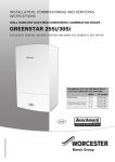
Ultracom2 35 Store
G.C. No. 47-019-15
Table of contents
INT RO D U C T I O N
1
2
3
4
Instructions guidance
1.1
1.2
1.3
1.4
Product documentation........................................................................................3
Associated documents.........................................................................................3
Explanation of symbols........................................................................................3
Guarantee registration.........................................................................................3
2.1
2.2
2.3
2.4
2.5
Safety devices.....................................................................................................3
Data label............................................................................................................4
Gas category .......................................................................................................4
Regulation and statutory requirements..................................................................4
Hydraulic schematic.............................................................................................5
Appliance description
Safety instructions and regulations
3.1
3.2
Safety instructions...............................................................................................6
Regulations ........................................................................................................6
4.1
4.2
Appliance............................................................................................................7
Packaging...........................................................................................................7
6.1
6.2
6.3
Location............................................................................................................10
Clearances........................................................................................................10
Ventilation ........................................................................................................10
7.1
7.2
7.3
7.4
Scope of delivery...............................................................................................11
Recommendations before installing....................................................................11
Dimensions.......................................................................................................13
Mounting ..........................................................................................................14
8.1
8.2
8.3
Gas and water connections.................................................................................15
Safety Discharge Valves.....................................................................................16
Connection to the condensate trap......................................................................18
Recycling
TECH N I C A L DATA
5
Ultracom2 35 Store
INSTA L L AT I O N
6
7
8
9
Appliance location
Appliance installation
Hydraulic connection
Evacuation of combustion gas
10
Remove the front panel
11
Electrical connections
9.1
9.2
Regulation.........................................................................................................20
Flue configuration description............................................................................22
11.1
11.2
11.3
11.4
11.5
11.6
Access to main board ........................................................................................24
Main board........................................................................................................25
Electrical wiring.................................................................................................25
External accessories...........................................................................................26
Testing the electrical connections.......................................................................26
Wiring diagram..................................................................................................27
-1-
Table of contents
12
13
14
Commissioning
12.1
12.2
12.3
12.4
12.5
12.6
12.7
12.8
12.9
Switching on.....................................................................................................28
Filling the CH system (Central heating)................................................................28
Filling DHW Circuit.............................................................................................28
Filling the Condensate Trap.................................................................................28
Initial lighting....................................................................................................29
Gas rates...........................................................................................................30
Testing heating system.......................................................................................30
Testing domestic hot water system......................................................................30
Completion........................................................................................................30
13.1
13.2
13.3
13.4
Heating circuit adjustment..................................................................................31
Appliance technical settings and parameter list...................................................31
CO2 measurement..............................................................................................36
Re-check and restart..........................................................................................36
15.1
15.2
15.3
15.4
Fault diagnosis..................................................................................................37
Fault memory.....................................................................................................38
Fault codes........................................................................................................38
Functional flow diagram.....................................................................................40
Specific adjustment
User information
MAIN T E N A N CE
15
16
Trouble-shooting
Gas conversion adjustments
16.1 Settings............................................................................................................41
16.2 Restart - re-check commissioning........................................................................42
17
Draining
17.1 Heating circuit...................................................................................................42
17.2 Domestic Hot water circuit .................................................................................42
18
19
20
Servicing
18.1
18.2
18.3
18.4
18.5
18.6
18.7
18.8
18.9
18.10
18.11
Annual Maintenance..........................................................................................43
Casing removing................................................................................................44
Combustion check and setting the air/gas ratio valve...........................................44
Servicing...........................................................................................................45
Silencer.............................................................................................................46
Central heating expansion vessel........................................................................46
DHW expansion vessel.......................................................................................46
Particle filter......................................................................................................47
Condensate trap................................................................................................47
Combustion block..............................................................................................48
Service completion............................................................................................49
19.1
19.2
19.3
19.4
19.5
19.6
19.7
General.............................................................................................................49
Boiler Access.....................................................................................................50
Viewing window.................................................................................................50
Hydraulic block..................................................................................................52
Combustion block..............................................................................................55
Condensate trap................................................................................................57
PCB...................................................................................................................58
Replacement of Parts
Spare parts
20.1 Short List of Parts..............................................................................................59
20.2 Short List of Parts..............................................................................................60
-2-
INTRODUCTION
INTRODUCTION
1
Instructions guidance
1.1
Product documentation
The instructions are an integral part of the appliance and must be
handed to the user on completion of the installation in order to
comply with the current regulation.
• Carefully read the manual, to understand all the information
to enable safe installation, use and servicing. No liability can
be accepted in the event of damage for not complying with the
guidance in this instruction manual.
These instructions consist of, Installation, Servicing, Fault Finding,
Replacement of Parts and Spares. The instructions are an integral
part of the appliance and must, to comply with the current issue of
the Gas Safety (Installation and Use) Regulations, be handed to the
user on completion of the installation.
1.2
Associated documents
-- 1 Instructions for use
-- 1 magnetic lighting instruction label
-- 1 flue guide
-- 1 extended guarantee leaflet
-- 1 guarantee envelope pack
-- 1 wall template
-- 1 gas conversion label
1.3
Explanation of symbols
a
DANGER: Risk of injuries.
e
DANGER: Risk of electric shock.
b
ATTENTION: Risk of damage to the appliance or to its
surroundings.
i
IMPORTANT: Important information.
1.4
The second year of guarantee, from the beginning of the 13th
month onwards after installation or manufacture, is conditional
upon the boiler having been serviced by a competent person
approved at the time by the Health and Safety Executive, in
accordance with the manufacturer’s recommendations. We
strongly recommend regular servicing of your gas appliance, but
where the condition is not met, any chargeable spare parts or
components issued within the applicable guarantee period still
benefit from a 12 month warranty from the date of issue by the
manufacturer.
We recommend you complete and return as soon as possible
your guarantee registration card. If your guarantee registration
card is missing you can obtain a copy or record your registration
by telephoning the Glow-worm Customer Service number 01773
828100.
2
Appliance description
2.1
2.1.1
Thank you for installing a new Glow-worm appliance in your home.
Glow-worm appliances are manufactured to the very
highest standard so we are pleased to offer our customers a
Comprehensive Guarantee.
Overheating safety
The appliance is designed to recognise the potential for an
overheat lockout and will shutdown before this happens.
2.1.2
Safety discharge valve
Heating and domestic discharge safety valves and a domestic hot
water pressure relief valve are fitted to the boiler. This valve must
not be touched.
-- The heating safety valve opens when the pressure in the
heating circuit exceeds 3 bars.
-- The domestic hot water safety valve opens when the pressure
in the heating circuit exceeds 10 bars.
• Should there be any discharge from the pipe, isolate the boiler
electrical supply and call your installer or Glow-worm’s own
service organisation.
2.1.3
Guarantee registration
Safety devices
Frost protection
The frost protection system operates the pump to start as soon as
the temperature in the heating circuit falls below 12°C. The pump
stops as soon as the temperature of the water contained in the
heating circuit reaches 15°C.
If the temperature in the heating system falls below 7°C, the
burner ignites until it reaches 35°C.
The frost-protection system is active when the appliance is
switched on.
The system alone cannot ensure that the installation is protected
against frost. An separate frost thermostat is necessary to control
the temperature of the system.
a
Your domestic water circuit (hot or cold) is not
protected by the boiler.
This product is guaranteed for 24 months from the date of
installation or 30 months from the date of manufacture,
whichever is the shorter, for parts and labour.
0020112185_PROTO_13 - 01/11 - Glow-worm
-3-
INTRODUCTION
2.1.4
Condensate drain blockage
During freezing conditions this may be due to the forming of ice
in the condense drain external to the house. In this case, a safety
device shuts down the appliance.
2.2
Data label
2.3
Gas category
This boiler is for use only on G20, but can be converted for use on
G31.
• To adapt the appliance to another type of gas, see the chapter
"Gas conversion".
The data label certifies the country where the appliance is
intended to be installed.
2.4
Data label location:
2.4.1
Regulation and statutory requirements
CE Mark
This boiler meets the requirements of Statutory Instrument,
No. 3083 The Boiler (Efficiency) Regulations, and therefore is
deemed to meet the requirements of Directive 92/42/EEC on the
efficiency requirements for new hot water boilers fired with liquid
or gaseous fuels.
Type test for purposes of Regulation 5 certified by: Notified body
1312.
Product/production certified by: Notified body 0086.
The CE mark indicates that the appliances described in this
manual are in compliance with the following directives:
-- European directive n°2009-142 relative to gas appliances
-- European directive n°2004-108 from the European Parliament
and Council relative to electromagnetic compatibility
1
Key
1 Data label
-- European directive n°2006-95 from the European Parliament
and Council relative to low voltage
The data label contains the following data:
-- European directive n°92-42 relative to the yield of boilers
-- The name of the manufacturer
-- The country of intended destination
-- The commercial name of the appliance and its serial number
-- The types of flues installations authorised
-- The appliance's gas category
-- The gas type, group and pressure, set in the factory
-- The DHW specific flow rate (D)
-- The maximum pressure in the heating circuit (PMS)
-- The maximum pressure in the domestic water circuit (PMW)
-- The NOx class of the appliance
-- The type and voltage of electricity supply
2.4.2
Local regulations
Benchmark places responsibilities on both manufacturers
and installers. The purpose is to ensure that customers are
provided with the correct equipment for their needs, that it is
installed, commissioned and serviced in accordance with the
manufacturer’s instructions by a competent person approved at
the time by the Health and Safety Executive and that it meets
the requirements of the appropriate Building Regulations. The Benchmark Checklist can be used to demonstrate
compliance with Building Regulations and should be provided to
the customer for future reference.
Installers are required to carry out installation, commissioning
and servicing work in accordance with the Benchmark Code
of Practice which is available from the Heating and Hotwater
Industry Council who manage and promote the Scheme.
• Visit www.centralheating.co.uk for more information.
-- The maximum power rating
-- The electrical protection class
-- The minimum and maximum heat input (Q)
-- The minimum and maximum power output (P)
-- The CE number and logo
a
-4-
The appliance shall only be connected to the gas
type(s) indicated on the data label.
0020112185_PROTO_13 - 01/11 - Glow-worm
INTRODUCTION
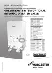
2.5
Hydraulic schematic
18
19
20
21
17
22
16
23
15
24
14
25
13
26
12
27
11
10
28
9
29
8
7
30
6
31
5
32
4
33
3
34
2
1
40
Key
1 Pressure reducer
2Filter on cold water inlet
3 Domestic hot water pump
4 Non-return valve
5 Heating circuit drain tap
6 Water pressure sensor
7 Heating pump
8 Heating return thermistor
9 Air vent
10 Heating flow thermistor
11 Condensate trap
12 Particle filter
13 Ignition and control electrode
14Burner
15 Main heat exchanger
16 Heating expansion vessel
17 Thermal fuse
18Flue outlet
19 Silencer
20Fan
21 Hot water safety valve
22 Discharge tube (not supplied)
23 Storage tank
24 Storage tank
25 DHW expansion vessel
0020112185_PROTO_13 - 01/11 - Glow-worm
39
38
37
36
35
26 Storage tank temperature sensor
27 Hot water temperature sensor
28 Gas control valve
29 Ignition module
30By-pass
31 Three way valve
32 Domestic plate to plate heat exchanger
33 Hot water heat exchanger output temperature sensor
34 Tundish
35 Gas isolating valve
36 Domestic hot water isolating valve
37 Heating safety valve
38 Heating flow isolating valve
39 Domestic cold water isolating valve
40 Heating return isolating valve
A
B
C
D
E
F
G
H
I
Heating return
Cold water inlet
Heating flow
Domestic hot water outlet
Gas
Condensate drain
Cold water supply
Heating safety valve drain
Hot water safety valve drain
-5-
INTRODUCTION
3
Safety instructions and regulations
3.1
Safety instructions
If the gas pressure at the input of the appliance is outside the
range specified, the appliance must not be put into operation.
e
Incorrect installation can cause electric shock or
appliance damage.
• Never disable security devices and do not try to adjust them.
• Protect all the electrical components from water while working
on the appliance.
• Use only original spare parts.
• Use only new O-rings and gaskets.
• After having completed work on gas or water carrying
components, check for their tightness.
• When work on the appliance is completed, perform an
operational test and check for safety.
With regards to the “Manual Handling Operations, 1992
Regulations”, the appliance exceeds the recommended weight for
a one person lift.
The handling of the boiler may involve lifting, pushing and
pulling, the use of a sack truck may be required.
3.2
• Be sure to consider the following handling techniques and
precautions:
Installation of this appliance falls within the scope of the Building
Regulations 2010 (Part G). This requires that the installation
of an unvented system should be notified to the local authority
Building Control Department and the work must be carried out by
a competent person as defined in the approved document G3.
-- Grip the appliance at its base
-- Use safety clothing where appropriate, e.g. gloves, safety
footwear.
• Ensure safe lifting techniques are used:
-- Keep back straight.
-- Avoid twisting at the waist.
-- Avoid upper body/top heavy bending.
-- Always grip using the palm of the hand.
-- Use designated hand holds.
-- Keep load as close to body as possible.
-- Always use assistance if required.
• Under no circumstances must the user interfere with or adjust
sealed parts.
• When assembling the connections, correctly position the seals
to avoid any leakage of gas or water.
• This appliance contains metal parts (components) and care
should be taken when handling and cleaning, with particular
regard to edges.
The basic safety instructions must be followed before attempting
to maintain or replace spare parts:
• Stop the appliance.
• Electrically isolate the appliance from the power supply.
• Turn off the appliance gas isolation valve.
• Hydraulically isolate the appliance using the isolation valves if
provided.
• Allow the appliance to cool before performing maintenance
work.
• Should you need to replace hydraulic components, drain the
appliance.
-6-
3.2.1
Regulations
Statutory requirements
IMPORTANT
Where no British Standards exists, materials and equipment
should be fit for their purpose and of suitable quality and
workmanship.
The installation of this boiler must be carried out by a competent
person approved at the time by the Health and Safety Executive
and in accordance with the rules in force in the countries of
destination.
Manufacturer’s instructions must not be taken as overriding
statutory requirements.
Statutory Requirements
In GB, the installation of the boiler must comply with the
requirements of the current issue of BS6798 and be carried out
by a competent person approved at the time by the Health and
Safety Executive and as described in the following regulations:
- The manufacturer’s instructions supplied.
- The Gas Safety (Installation and Use) Regulations.
- The appropriate Buildings Regulations either The Building
Regulations, The Building Regulations (Scotland), The Building
Regulations (Northern Ireland).
- The Water Supply (water fittings) Regulations 1999 and water
byelaws 2000, Scotland.
- The Health and Safety at Work Act, Control of Substances
Hazardous to Health (COSHH).
- Any electrical work must conform to BS7671 and part P of the
building regulations where applicable.
Where no specific instructions are given, reference should be
made to the relevant British Standard Code of Practice.
In IE, the installation must be carried out by a competent person
approved at the time by the Health and Safety Executive and
installed in accordance with the current edition of I.S.813
“Domestic Gas Installations”, the current Building Regulations
and reference should be made to the current ETCI rules for
Electrical Installation.
GB: the following Codes of Practice apply: BS4814, BS6798,
BS5440 Part 1 and 2, BS5546 Part 1, BS5449, BS6891, BS6700,
BS7074 Part 1 and 2, BS7593, BS7671.
IE: I.S.813, BS5546, BS 5449, BS 7074, BS 7593.
0020112185_PROTO_13 - 01/11 - Glow-worm
INTRODUCTION
NOTE: For further information, see the current issue of the
Building Regulations, approved document L1 ( in the UK) and the
following current issues of:
1) Central heating system specification (CheSS) and
2) Controls for domestic central heating system and hot water.
BRECSU.
Gas Supply
The gas installation must be in accordance with the relevant
standards.
In GB, this is BS6891.
In IE, this is the current edition of I.S.813 “Domestic Gas
Installations”.
The supply from the governed meter must be of adequate size to
provide a steady inlet working pressure of 20mbar (8in wg) at the
boiler. On completion, test the gas installation for tightness using
the pressure drop method and suitable leak detection fluid, purge
in accordance with the above standard.
Domestic Hot Water
All domestic hot water circuits, connections, fittings must be
in accordance with the relevant standards and water supply
regulations.
Heating System
In GB, it is necessary to comply with the Water Supply (Water
Fittings) Regulations 1999 (for Scotland, the Water Byelaws
2000, Scotland). To comply with the Water regulations your
attention is drawn to: The Water Regulations guide published by
the Water Regulations Advisory Service (WRAS) gives full details
of the requirements.
In IE, the requirements given in the current edition of I.S.813
“Domestic Gas Installations” and the current Building
Regulations must be followed.
3.2.2
Gas Safety (Installation and Use) Regulations
In your own interests and that of safety, it is the Law that ALL gas
appliances are installed by a competent person approved at the
time by the Health and Safety Executive in accordance with the
current issue of these regulations.
Control of Substances Hazardous to Health
Under Section 6 of The Health and Safety at Work Act 1974, we
are required to provide information on substances hazardous to
health. The adhesives and sealants used in this appliance are
cured and give no known hazard in this state.
Insulation Pads:
These can cause irritation to skin, eyes and the respiratory tract.
If you have a history of skin complaint you may be susceptible to
irritation. High dust levels are usual only if the material is broken.
Normal handling should not cause discomfort, but follow normal
good hygiene and wash your hands before eating, drinking or
going to the lavatory.
• If you do suffer irritation to the eyes or severe irritation to the
skin seek medical attention.
4
Recycling
i
4.1
In GB, this is BS 7671.
In IE, this is the current edition of ETCI rules.
The boiler MUST be connected to a permanent 230V ac, 50Hz
supply.
Connection of the whole electrical system of the boiler, including
any heating controls, to the electrical supply MUST be through
one common isolator and must be fused 3 Amp maximum.
Isolation should be by a double pole switched fused spur box,
with a minimum gap of 3mm for both poles. The fused spur
box should be readily accessible and preferably adjacent to the
appliance. It should be identified as to its use.
The recycling of the packaging must be carried out by
the qualified professional who installed the appliance.
Appliance
Most of the appliance is made of recyclable materials.
This symbol indicates that this appliance must not
be disposed of with household waste, that it should
be selectively collected for energy recovery, reuse or
recycling.
Electrical Supply
The boiler MUST be earthed. All system components shall
be of an approved type and all wiring to current I.E.E. wiring
regulations. External wiring must be correctly earthed, polarised
and in accordance with the relevant standards.
Other regulations
• Take the appliance to an appropriate collection point.
i
4.2
By complying with this directive, you will contribute
to the preservation of natural resources and the
protection of human health.
Packaging
We recommend that you recycle the packaging of the appliance in
a responsible fashion.
• Sort the waste in order to separate those elements which can
be recycled (cardboard, plastics ...) and those which cannot be
recycled.
• Eliminate the waste in accordance with existing regulations.
Alternatively connection can be made through an unswitched
shuttered socket and 3A fused 3-pin plug both to the current
issue of BS 1363, provided they are not used in a room containing
a bath or shower.
Wiring to the boiler must be PVC 85OC insulated cable, not less
than 0.75mm2 (24/0.20mm).
0020112185_PROTO_13 - 01/11 - Glow-worm
-7-
TECHNICAL DATA
TECHNICAL DATA
5
Ultracom2 35 Store
Boiler, type C13, C33, C43
Description
Unit
Gas category
35 Store
ll2H3P
SEDBUK 2005 rating
%
NA
SEDBUK 2009 rating
%
NA
kW
G20
30.6
kW
8.5
kW
30
Heating
Maximum heating input power
Minimum heating output power
at 80/60°C (P min.)
Maximum heating output power
at 80/60°C (P max.)
Minimum heating output power
at 50/30°C (P min.)
Maximum heating output power
at 50/30°C (P max.)
PCI Efficiency max heating power
at 80/60°C
PCI Efficiency max heating power
at 50/30°C
Efficiency at part load (30%) on PCI
at 40°C/30°C
Efficiency level according to the European
Directive 92/42
Minimum calorific rate (Q min.)
Maximum calorific rate (Q max.)
Minimum heating flow rate
Minimum heating temperature
Maximum heating temperature
Content of heating expansion vessel
Heating expansion vessel preset pressure
Max. capacity of the installation at 75°C
Heating safety valve preset pressure (PMS)
kW
9.3
kW
32.5
%
97.9
%
106.3
%
108.6
-
Condensing
kW
kW
l/h
°C
°C
l
gallons
bar
psi
l
bar
MPa
8.7
30.6
400
10
80
12
2.64
0.75
10.9
220
3
0.3
G20
Domestic Hot Water
Minimum DHW output power (P min.)
kW
8.7
Maximum DHW output power (P max.)
kW
35.7
kW
kW
°C
°C
l/min
l/min
8.7
35.7
45
65
19.7
NA
-
***
l/min
l
l/min
bar
psi
bar
psi
bar
psi
0.1
42
16
10
145
0.3
4.3
10
145
Min. calorific rate (Q min)
Maximum calorific rate (Q max.)
Minimum DHW temperature
Maximum DHW temperature
Specific flow rate (∆T of 35 K)
Specific flow rate according to EN 625
Level of sanitary confort
EN 13203
Flow rate operating threshold
High capacity tank
Water flow limitor
Safety valve, maximum working pressure
(PMW)
Minimum inlet water pressure
Maximum inlet water pressure (*)
-8-
Description
Maximum temperature hot water safety
valve
Unit
35 Store
°C
90
bar
10
psi
145
(*) For a supply pressure above 3 bar, it is recommended that you install
a pressure reducer.
Maximum pressure hot water safety valve
Description
Unit
Combustion
Fresh air flow rate (1013 mbar -0°C)
35 Store
G20
45.7
4
13.8
16
72.4
47.4
77.2
55.8
m /h
Flue gas flow rate at Pmin.
g/s
Flue gas flow rate at Pmax.
g/s
Flue gas flow rate in hot water mode
g/s
Flue gas temperature at Pmin. 80°C/60°C
°C
Flue gas temperature at Pmin. 50°C/30°C
°C
Flue gas temperature at Pmax. 80°C/60°C
°C
Flue gas temperature at Pmax. 50°C/30°C
°C
Flue gas temperature in hot water mode
°C
81
(with hot water temperature of 50°C)
Value of combustion products (measured at nominal calorific rate and
with G20 reference gas, in heating):
ppm
NA
CO mg/
8
kWh
%
9.2
CO2
ppm
22.6
Weighted Nox mg/
39.8
kWh
Appliance NOx class
5
Electrical
Electrical supply
V/Hz
230/50
Standby mode electrical power
W
6
Operational mode electrical power (Max)
W
178
Intensity
A
0.75
Internal fuse rating on main PCB
A
2
Index of electrical protection
IPX4D
(EN 60529)
Electrical classification
I
3
Description
Unit
35 Store
Gas connection Ø O.D.
Heating flow and return connection Ø O.D.
Domestic Hot Water connection Ø O.D.
Safety valve discharge connection Ø O.D.
mm
mm
mm
mm
15 (copper)
22 (copper)
22 (copper)
22 (copper)
0020112185_PROTO_13 - 01/11 - Glow-worm
TECHNICAL DATA
Description
Unit
35 Store
Height
Width
Depth
Weight
Total weight (installed)
Number of CE certificate
mm
mm
mm
kg
kg
990
470
570
67
115.5
1312 CL 5531
Description
Unit
Maximum DHW gas rate
Description
Unit
35 Store
Maximum DHW gas rate
kg/h
2.77
Maximum heating gas rate
kg/h
2.37
Minimum gas rate
kg/h
Propane Gas G 31 (15 °C, 1013.25 mbar)
Dimensions:
0.67
10.3
± 0.3%
10.1
± 0.2%
CO2 at Qmax DHW + "tolerance case ON"
%
CO2 at Qmax DHW + "tolerance case OFF"
%
35 Store
CO2 at Qmin +
"tolerance case ON"
%
9.8
± 0.3%
m3/h
3.77
%
Maximum heating gas rate
m3/h
3.24
CO2 at Qmin +
"tolerance case OFF"
9.6
± 0.2%
mbar
37
Minimum gas rate
3
m /h
0.92
CO2 at Qmax DHW + "tolerance case ON"
%
9.2 ± 0.3%
CO2 at Qmax DHW + "tolerance case OFF"
%
9 ± 0.2%
CO2 at Qmin +
"tolerance case ON"
%
8.9 ± 0.3%
CO2 at Qmin +
"tolerance case OFF"
%
8.7 ± 0.2%
mbar
20
Natural Gas G 20 (15 °C, 1013.25 mbar)
Inlet pressure
0020112185_PROTO_13 - 01/11 - Glow-worm
Inlet pressure
-9-
INSTALLATION
INSTALLATION
i
6
consideration should be given for the space required to insert the
flue from inside the property, which may necessitate clearance
larger than those specified in diagram below.
All the drawings dimensions are shown in mm.
i
The appliance can be placed with zero clearance on
the left hand side if practical to do so.
Appliance location
6.1
6.1.1
ØA
Location
+5
ØA
Instructions
mi
n.
Before choosing a site for the appliance, carefully read the safety
warnings and installation manual.
• Ensure that wall to which the appliance will be mounted on is
structurally safe in order to support the weight of the appliance.
• Ensure that the space that the appliance is to be installed
within allows the appliance to be installed and the clearances
maintained. This will ensure that the connections to the water,
gas and flue can be accessed and inspected (see chapter
Clearances).
5
mi0
n.
30
mi 0
n.
• Explain these requirements to the appliance user.
• Do not install the appliance above another appliance that
could damage it (for example, above a cooker that might emit
steam or grease) or in a room, which has a lot of dust in the
atmosphere which is corrosive.
*
600n.
i
m
• The boiler must be fitted inside the property and exposed pipe
work may need to be protected from frost by fitting a frost
thermostat.
6.1.2
This boiler is not suitable for outdoor installation.
This boiler may be installed in any room, although particular
attention is drawn to the installation of a boiler in a room
containing a bath or shower where reference must be made to the
relevant requirements.
This boiler is suitable for installation in bathroom zones 2 and 3.
In GB this is the current I.E.E. WIRING REGULATIONS and
BUILDING REGULATIONS.
In IE reference should be made to the current edition of I.S.813
“Domestic Gas Installations” and the current ETCI rules.
Timber Frame Buildings
If the boiler is to be installed in a timber frame building it should
be fitted in accordance with the Institute of Gas Engineers
document IGE/UP/7/1998. If in doubt seek advice from local gas
undertaking or Glow-worm.
6.2
Clearances
• To allow periodic maintenance, ensure the distances indicated
on the diagram.
Additional clearances may be beneficial around the boiler for
installation and servicing.
For flue installations where external access is not practicable,
- 10 -
30
mi 0
n.
Regulations
Location
15
mi 0
n.
Key
* A removable compartment door can be placed a minimum 5 mm in
front of appliance. A clearance of 600 mm is required from a fixed
surface.
The boiler and flue are suitable for installation onto and through
combustible materials provided that:
-- Minimum 5mm clearance is maintained around the
circumference of the flue (air intake).
-- The combustible surface and fixings are suitable for
supporting the load.
-- The minimum clearances from the boiler case are maintained.
6.3
6.3.1
Ventilation
Room Ventilation
The boiler is room sealed so a permanent air vent is not required.
6.3.2
Cupboard or Compartment Ventilation
Due to the high efficiency and low casing temperature of this
boiler, cupboard or compartment ventilation is not necessary.
• Existing ventilation should be investigated for its purpose
before removing.
0020112185_PROTO_13 - 01/11 - Glow-worm
INSTALLATION
7
Appliance installation
7.1
3
3.1
3.2
3.3
3.4
3.5
3.6
3.7
Scope of delivery
The appliance is delivered in a single carton with a document
pack and fittings.
i
The flues package will be ordered according to the
configuration of the installation.
Documents bag
Installation and servicing manual
Flue book
Instructions for use
Extended guarantee leaflet
Guarantee envelope pack
Magnetic lighting instruction label
Gas conversion label
7.2
• Please check the contents.
7.2.1
2.10
(x1)
(x1)
(x1)
(x1)
(x1)
(x1)
(x1)
(x1)
Recommendations before installing
Domestic hot water circuit design
1
Water pressure
5
2.9
4
2.8
2.7
3
6
2.6
2
2.5
3
7
1
2.4
3.1
2.3
3.2
3.4
Key
1 Domestic hot water out
2 Pressure reducing valve (if required)
3 Mixing valve
4Boiler
5 Temperature/pressure relief valve
6Filling loop in accessory box
7 Domestic cold water supply in
3.5
The minimum working pressure to obtain the maximum domestic
flow is 1,0 bar.
3.3
2.2
2.1
2
3.7
Key
1
Boiler
2
2.1
2.2
Accessories bag
Wall template
Fittings pack
- Heating return valve
- Cold water inlet valve
- Heating flow valve
- Domestic hot water connection
- Gas isolation valve
- Compression fitting
2.3 Seals bag
2.4 Filling loop
2.5 Pressure reducing valve
2.6 Pressure relief valve
2.7 Check valve
2.8 Tundish
2.9 Hanging bracket
2.10 Mixing valve
0020112185_PROTO_13 - 01/11 - Glow-worm
3.6
The boiler is supplied with a pressure reduction valve pre-set to
deliver an inlet pressure of 3.5bar.
(x1)
(x1)
(x1)
(x1)
(x1)
(x1)
(x1)
(x1)
(x1)
(x1)
(x1)
(x1)
(x1)
(x1)
(x1)
(x1)
(x1)
(x1)
‘Hard’ water areas
The temperatures within the heat exchanger are limited by the
boiler control system to minimise scale formation within the hot
water pipework. However, in areas where the water is ‘hard’ (i.e.
more than 200 mg/L of calcium carbonate), it is recommended
that the hot water setting is reduced and that a scale reducer is
fitted, refer to the manufacturer’s instructions or consult the local
water company for additional advice.
Domestic water flow rate
The domestic hot water flow has a restrictor, factory fitted, which
reduces the flow to a maximum of:
-- 35 Store ▸ 16 l/min.
- 11 -
INSTALLATION
Prevention of scalding - Thermostatic mixing valve
Key
1 Drain point
2 External bypass (if required)
3 Domestic cold water supply in
4 Domestic hot water out
5 Pressure reducing valve (if required)
6Boiler
7Filling loop in accessory box
8 Additional expansion vessel (if required)
9 Heating return circuit
10 Heating flow circuit
B
A
C
General
This boiler is designed for use as part of a sealed water central
heating system with fully pumped circulation. The pump,
expansion vessel and associated safety devices are all fitted
within the boiler.
2
1
Key
1
2
A
B
C
Safety valve
Thermostatic mixing valve
Standard flue length horizontal
Hot water
Cold water
Mixed water
The safety valve is an integral part of the boiler and it cannot
be adjusted. The pipe from the safety discharge valve must
discharge safely in accordance with standards.
A thermostatic mixing valve is used in the domestic hot water
circuit.
Expansion vessel
The boiler has an integral expansion vessel with a capacity of 12
litres (2.64 gallons), with a charge pressure of 0.75bar.
It’s function is to maintain the temperature of the mixed water,
supplied to the user, constant at the set value when there
are variations in the supply pressure and temperature of the
incoming hot and cold water or in the flow rate.
The hot water supply temperature to a bath should be limited to
a maximum of 48°C. The thermostatic mixing valve should not be
easily altered by users.
The thermostatic mixing valve conforming to WRAS, BS EN 1111
and BS EN 1287, compliant to Part G of the bluiding regulations.
7.2.2
i
The heating system volume should be calculated to
ensure that the expansion vessel is suitable, it may be
necessary to add an additional vessel.
-- In GB, Guidance on vessel sizing is also given in the current
issue of BS5449 and BS7074 Part 1.
-- In IE, current edition of I.S.813 “Domestic Gas Installations”.
Bypass
Heating circuit design
The boiler is fitted with an automatic bypass which can be
adjusted to suit your system requirements.
• Ensure that under no circumstances does the flow rate drop
below the figure specified, refer to chapter "Technical data".
Filling the sealed system
6
7
5
8
4
9
i
The water pressure at the boiler must be at least
1.2bar to operate the filling loop. If the pressure is
less than 1.2bar an external filling loop must be fitted.
If this pressure is not available contact the local water
authority.
Suitable external filling systems are shown diagrammatically, see
diagram overleaf.
3
2
10
1
- 12 -
0020112185_PROTO_13 - 01/11 - Glow-worm
INSTALLATION
Water treatment
Existing system- It is essential that prior to installing the new
boiler the system is thoroughly flushed.
3
4
2
7
1
New system- For optimum performance after installation, the
boiler and its associated central heating system should also be
flushed.
5
Flushing shall be carried out in accordance with BS 7593, a
chemical cleanser can be used either Sentinel X300, X400 or
Fernox F3 are suitable.
6
It is recommended to flush existing systems first before fitting the
new boiler.
• Ensure all cleanser is removed from the whole system before
adding an inhibitor.
5
3
8
2
9
1
7
Key
1 Heating flow circuit
2 Heating return circuit
3Boiler
4 Double check valve assembly
5 Domestic cold water supply in
6 Temporary filling loop (remove immediately after filling)
7 Drain point
8Back flow prevention device
9 Tundish
For long-term corrosion protection after flushing, an inhibitor
suitable for stainless steel heat exchangers can be used. Either
Sentinel X100 or Fernox F1 inhibitor can be used.
Artificially softened water- BS7593 notes that soft water has
an increased potential for corrosion and this may influence the
choice of corrosion inhibitor. Where water is artificially softened,
it is advisable to feed unsoftened water to drinking water taps.
The boiler primary circuit should only be filled with unsoftened
water.
7.3
Dimensions
361
=
=
100
The system should be pressurised to 0.8bar, indicated on the
digital display with no heating demand.
Drain points
Drain taps must be provided at all low points of the system, which
will allow the entire system to be drained.
890
Drain taps shall be to the current issue of BS2879.
470
0020112185_PROTO_13 - 01/11 - Glow-worm
561
- 13 -
INSTALLATION
7.4
Mounting
• Make sure that the equipment used for implementing the
installation is compatible with that of the appliance.
• Determine the assembly location. See the "Appliance location"
chapter.
Wall template
Standard flue length horizontal
2.5° 44mm/metre inclined extended flue length
Wall plug
Hanging bracket
Screw (not supplied)
Flue hole cutting
=396=
Ø130**
Ø105*
36
129
Key
1
2
3
4
5
6
• Mark the position of the flue centre.
• Remove the wall template, then drilling the flue hole.
i
The flue is designed with an internal fall of 44mm/
metre (2.5o), therefore the hole can be drilled
horizontally.
• Use a 105mm diameter core drill for external access flue
installation (60/100 flue) (80/125 flue ▸ Ø130mm).
0
6
• If fitting an extended side flue, determine the flue hole centre
by extending the dashed inclined line on the template to the
side wall. This dashed line is drawn at 44mm/metre (2.5o)
rise from the boiler. Where this line reaches the side wall, a
horizontal line should be marked. The vertical centre line of
the flue should then be marked at 130mm from the back wall.
To allow for the flue passing through the wall at this angle
a 125mm hole should be drilled irrespective of internal or
external installation.
36
102
70
70
38
* 60/100 flue
** 80/125 flue
Hanging bracket fixing
Due to the varied site conditions, fixings are not supplied and
advise that the installer should supply those which are suitable.
• Take the wall template and place in the desired position
on the wall, giving due consideration to the required boiler
clearances, see chapter "Appliance location ▸ Clearances",
and the flue you are fitting.
7.4.1
3
If flue extension pipes are to be used then a core
drill size of 125mm is required. This will allow the
extension pieces to slope at 44mm/metre (2.5o)
towards the boiler.
• If fitting a side flue, extend the flue centre line into the corner
then 130mm along the adjacent wall.
193
62.4
i
14.7
890.4
875.7
• Use a 125mm diameter core drill for internal access only flue
installation (60/100 flue) (80/125 flue ▸ Ø150mm).
• Drill the holes for the fixing screws in accordance with the wall
template.
• Fix the hanging bracket on the wall.
Fixing to the wall
361
2
1
90°
4
5
6
- 14 -
0020112185_PROTO_13 - 01/11 - Glow-worm
INSTALLATION
7.4.2
a
Boiler hanging
With regards to the Manual Handling Operations,
1992 Regulations, the following lift operation exceeds
the recommended weight for a one person lift, refer to
chapter "Manual Handling".
8
Hydraulic connection
8.1
Gas and water connections
The whole of the gas installation, including the meter, should be
inspected, tested for tightness and purged in accordance with the
current issue of BS6891 and in IE the current edition of I.S.813
“Domestic Gas Installations”.
2
i
1
The appliance may contain a small amount of water,
place a water container beneath the boiler connections.
• Take care to clean the pipes before assembly removing any
debris or burrs. Grease and oils may need to be removed they
are not possible to remove by cleansing and flushing. Foreign
bodies in the system may enter the appliance and interrupt its
operation.
• Do not use any solvent products, due to the risk of damaging
the circuit.
a
Do not perform any 'hot work' directly under the
appliance, this may cause damage to the appliance
base. Heat may also damage the isolation valves.
Always pre-assemble pipes before fitting them to the
boiler.
• Only use original seals supplied with the appliance.
• Check that there are no leaks. Repair if necessary.
Key
1Boiler
2 Hanging bracket
• Lifting the boiler into position, lean the top of the boiler
slightly to the wall and position just above the hanging
bracket.
• Lower the boiler slowly and engage onto the hanging bracket
6
5
4
3
7
2
1
Key
1 Gas service isolating valve with pressure test point + sealing washer
½"
2 Domestic hot water outlet isolating valve + sealing washer ¾"
3 Heating flow isolating valve + sealing washer ¾"
4 Cold water inlet isolating valve + sealing washer ¾"
5 Heating return isolating valve + sealing washer ¾"
6 Connection Ø O.D. 22 mm
7 Gas connection Ø O.D. 15 mm
• Use only the original gas cock GER/1 DN15, CE-0085 CL 0082
• Use only the olive and flat seal washer supplied with the gas
cock.
0020112185_PROTO_13 - 01/11 - Glow-worm
- 15 -
INSTALLATION
8.2
Safety Discharge Valves
8.2.1
• Connect the safety valves. The drain equipment must allow the
water flow to be seen.
Heating safety valve
This must be extended, using not less than 15mm o.d. pipe,
to discharge, in a visible position, outside the building, facing
downwards, preferably over a drain.
To ease future servicing it is advisable to use a compression type
fitting to extend the safety discharge valve tube.
The pipe must have a continuous fall and be routed to a position
so that any discharge of water, possibly boiling, or steam cannot
create any danger to persons, damage to property or external
electrical components and wiring.
8.2.3
Discharge
2
1
D1: 600 mm max.
H
3
D2: 300 mm min.
2
Key
1
2
3
H
3
Pressure relief valve pipe
Heating safety valve
Compression fitting
Pressure relief valve outlet - to outside
8.2.2
Combined temperature and pressure relief valve
1
4
Key
1 Tundish
2 Pressure relief valve
3 Trapped gully
4Fixed grating
Combined Temperature and Pressure relief and Expansion Valve
Discharge arrangement
2
1
I
Key
1 Pipe for Pressure relief valve
2 DWH safety valve
I
Pressure relief valve outlet - to outside
- 16 -
The outlet connections of the temperature and pressure relief
valve must be connected to the tundish privided. The tundish
must be installed with no greater than 600mm of 15mm pipe (D1)
with the tundish fitted in the vertical position. It is permissable
to connect the expansion valve to this pipe if practicable to do
so, by means of a tee piece. If not the expansion valve must be
fitted with a tundish and discharged using the same methods.
The Tundish must be left in a visible position for the user and
in the same space as the boiler and away from any electrical
components.
The pipe connected to the underside of the tundish (D2) must be
vertical for the first 300mm of length before any bend or elbow,
then any horizontal pipework must be installed with a fall of
at least 1 in 200 to its final discharge location. The pipe must
be either metal or other approved safe material (e.g complying
with BS 7921-1 2006). The minimum pipe size is 22mm copper
(or equivilent internal diameter material). To calculate the D2
pipe maximum equivilent length see the table and the worked
example. As an alternative BS 6700:2006 can be used.
0020112185_PROTO_13 - 01/11 - Glow-worm
INSTALLATION
Sizing of copper discharge pipe "D2" for common
temperature relief
Valve outlet size
Minimum size of discharge
pipe D1
G1/2
G3/4
G1
Minimum size of discharge
pipe D2 from tundish
Maximum resistance
allowed, expressed as a
length of straight pipe (i.e.
no elbows or bends
Resistance created by each
elbow or bend
22mm
Up to 9m
0.8m
28mm
Up to 18m
1.0m
35mm
Up to 27m
1.4m
22mm
Up to 9m
1.0m
28mm
Up to 18m
1.4m
35mm
Up to 27m
1.7m
22mm
Up to 9m
1.4m
28mm
Up to 18m
1.7m
35mm
Up to 27m
2.3m
15mm
22mm
28mm
The above table is based on copper tube. Plastic pipes may be
of different bore and resistance. Sizes and maximum lengths of
plastic should be calculated using data prepared for the type of
pipe being used.
Worked example
The product is supplied with a G1/2 T&P valve the pipe D2 is
measured to be 4m in length from the tundish to the point of
discharge with 4 elbows.
7m of 22mm pipe = 4m
4 22mm elbows = 0.8 X 4 = 3.2m
3.2 + 4 = 7.2m and permissable in 22mm pipe should the
calculation not be permissable in 22mm the pipe must be
increased to 28 or even 35mm copper pipe or internal diameter
equivilent.
If in multiple dwellings a common discharge pipe is used it
should be at least one pipe size larger than the largest individual
discharge pipe to be connected.
Termination of the discharge pipe
i
Acceptable terminations are
1. Into a trapped gully, the end of the pipe may be below the
grating but above the water seal
2. Facing downward and up to 100mm above an external surface
(providing a type of wire cage is fitted to prevent contact)
3. Discharged at a high level into a metal hopper and downpipe
(the end of the pipe must be visible)
4. Discharged onto a roof providing that
-- a. The roof is constructed of a material designed to withstand
the temperatures
-- b. The gutter or drain system connected to the roof is at least
3m away from the point of discharge
Connection into soil stacks
Under normal circumstances it is not permissable to discharge
the pipe (D2) into a soil stack unless the following conditions are
met
1. The soil stack and its seals are clearly designed and marked
to withstand the temperatures of the water which could be
discharged under fault conditions.
2. A mecahnical type seal trap is used (water traps are not
permitted) with a temperature rating defined as above
3. It is a separate branch pipe with no other sanitary appliances
connected to it.
4. If the branch pipe used is plastic it must be either
-- a. Polybutalene (PB) Class S of BS 7921-2:2006
The discharge pipe must terminate in a safe place where
there is no risk to persons in the vicinity of the discharge.
b
The tundish should be installed so that is is visible to
the occupants and is positioned away from electrical
devices.
b
The discharge pipes (tundishes) drain valves
etc. shall be positioned away from any electrical
components.
b
Cylinder relief valve connections should not be used
for any other purposes.
b
No valve should be fitted between the expansion
valve and the storage cylinder.
-- b. Cross linked polyethylene (Pe-X) Class S of BS 7921-3:2006
-- c. A continuous marking applied to the pipe to warn that no
sanitary appliance may be fitted to it
0020112185_PROTO_13 - 01/11 - Glow-worm
- 17 -
INSTALLATION
8.5
Connection to the condensate trap
a
Condensate produced by the appliance is mildly
acidic (pH 3.5 - 5.0). Use protective gloves
b
Condensate must only be discharged in accordance
with these instructions.
i
The volume of condensates evacuated can reach about
15 litres per day for a detached house. This volume
is negligible compared to the volume of waste water
discharged by a house, because the condensates are
diluted in this water.
• If this is not practicable, discharge can be allowed into the
external household drains or a purpose designed soak away,
refer to diagram overleaf.
It is recommended that any external condensate drain pipe is
protected and also preferably of 32mm diameter, to prevent
freezing in adverse weather conditions.
• Always ensure the pipe is installed with the correct fall
• Use push fit plastic pipe to connect to the condensate outlet do not use metal pipes. It is permissible to use a condensate
neutraliser providing that it is checked for correct operation.
• Refer to BS5546 or BS6798 for advice on disposal of boiler
condensate.
1
Key
1 Condensate pipe
• Make sure there is no protective plug fitted.
• Connect the condensate pipe (1).
i
The pipe should have a fall of a least 2.5° 44mm/
metre away from the boiler.
Condensate should, if possible be discharged into the household
internal drainage system.
- 18 -
0020112185_PROTO_13 - 01/11 - Glow-worm
INSTALLATION
0020112185_PROTO_13 - 01/11 - Glow-worm
- 19 -
INSTALLATION
9
Evacuation of combustion gas
9.1
b
Regulation
b
Only flue accessories supplied by Glow-worm must be
used.
Caution! The connection between the flue elbow and
the flue outlet must be sealed.
In GB the minimum acceptable siting dimensions for the terminal
from obstructions, other terminals and ventilation openings are
shown in diagram overleaf.
Different flue outlet configurations can be carried out.
In IE the minimum distances for flue terminal positioning must be
those detailed in I.S.813 “Domestic Gas Installations”.
• Consult your supplier for more information about the other
possibilities and associated accessories.
The terminal must be exposed to the external air, allowing free
passage of air across it at all times.
44 mm/m
1
Being a condensing boiler some pluming may occur from the flue
outlet. This should be taken into consideration when selecting
the position for the terminal.
2
4
3
• Standard flue terminal kits have an in-built fall back to the
boiler to drain the condensate. These can be fitted level
between the appliance and the termination position. All other
extended flues must have a fall of at least 44mm/m
Carports or similar extensions of a roof only, or a roof and one
wall, require special consideration with respect to any openings,
doors, vents or windows under the roof. Care is required to
protect the roof if made of plastic sheeting. If the carport
comprises of a roof and two or more walls, seek advice from the
local gas supply company before installing the boiler.
b
If the flue terminal is positioned near a light source
insects may enter the flue system. Where safe and
practical to do so advise the homeowner to check the
flue outlet and clear visible insects from the terminal
end.
The maximum length of the flue outlet is defined according to its
type (for example C13).
• Whatever the kind of flue system chosen, observe the
minimum distances indicated in the chart overleaf to position
the flue terminals.
• To install the flue, refer to the separate flue instruction
supplied with your appliance.
• Explain these requirements to the user of the appliance.
a
- 20 -
If necessary, you must install a terminal protection kit.
0020112185_PROTO_13 - 01/11 - Glow-worm
INSTALLATION
Position
Position of the flue terminal
Horizontal flues
directly below an opening, air brick,
A
opening windows
B
above an opening, air brick, opening windows
horizontally to an opening, air brick, opening
C
windows
D
below gutter, drain/soil pipe
E
below eaves
F
below a balcony or car port
G
from vertical drain pipes and soil pipes
H
from internal/external corners
H*
to a boundary alongside the terminal
I
above adjacent ground or balcony level
J*
from surface or a boundary facing the terminal
0020112185_PROTO_13 - 01/11 - Glow-worm
mm
Position
from opening (door/window) in car port
into dwelling
M
vertical from a terminal
N
horizontally from a terminal
Vertical flues
P
from another terminal
Q
above roof level
R
from adjacent opening window
S
from adjacent wall to flue
L
300
300
300
25
25
25
25
25
300
300
600
Position of the flue terminal
mm
1200
1500
300
600
300
1000
300
(*) These dimensions comply with the building regulations,
but they may need to be increased to avoid wall staining and
nuisance from pluming depending on site conditions.
- 21 -
INSTALLATION
9.2
Flue configuration description
Ø 80/125 mm
1
361
L
120
174
61
100
=
470
=
1
Key
1 DWH safety valve
b
9.2.1
Be careful not to damage the DWH safety valve
during installation of the flue.
Horizontal concentric flue Ø 60/100 mm
or Ø 80/125 mm (C13 type installation)
a
If necessary, you must install a terminal protection kit.
Ø 60/100 mm
Key
1 Gasket (fitted)
Type
Max length
Ø 60/100
Ø 80/125
10 m
12 m
Each time an additional 90° bend is necessary (or 2 at 45°), the
length (L) must be reduced by 1 m.
L
1
63
Key
1 Gasket (fitted)
- 22 -
0020112185_PROTO_13 - 01/11 - Glow-worm
INSTALLATION
9.2.2
Vertical concentric flue Ø 60/100 mm
or Ø 80/125 mm (C33 type installation)
9.2.3
Multiple boiler chimney flue
Ø 60/100 mm (C43 type installation)
b
The flue connecting from the appliance to the flue
system must be supplied from the manufacturer of the
boiler.
b
C43 flue systems must not be a 'pressurised system'
but act under natural draught principles
b
C43 type flue systems must have their own
condensate drain fitted and not allow condensate to
mix into other appliances
L
L
4
3
A
Type
Max length (L)
Ø 60/100
Ø 80/125
10 m
13 m
Each time an additional 90° bend is necessary (or 2 at 45°), the
length (L) must be reduced by 1 m.
2
1
B
5
Key
1 Pressure balancing system
2 Air-inlet pipe
3 Collector pipe
4Boiler
5 Inspection hatch
AFinal storey
B Ground floor
Type
Max length (L)
Ø 60/100
10 m
Each time an additional 90° bend is necessary (or 2 at 45°), the
length (L) must be reduced by 1 m.
0020112185_PROTO_13 - 01/11 - Glow-worm
- 23 -
INSTALLATION
10 Remove the front panel
11.1 Access to main board
i
It is necessary to remove the appliance front cover.
B
2
23
0
V
2
1
A
1
A
Key
1Front panel retaining screw
2Front panel
Key
1 User interface
2Fastening screw
• Pivot the user interface to access the electrical panel.
• Undo the two screws (1) on the underside of the front panel
and remove the front panel (2).
11 Electrical connections
23
e
Incorrect installation can cause electric shock or
appliance damage. The electrical connection of the
appliance must be made only by a qualified engineer.
0
V
2
The appliance must be connected directly to an accessible, fixed,
switched, electrical outlet.
The external wiring must be earthed, with correct polarity and in
accordance with current standards.
The manufacturer declines any responsibility for damages to
persons or others caused by the incorrect installation of the
appliance earthing. This includes failure to comply with current
standards.
Electrical components have been tested to meet the equivalent
requirements of the BEAB.
• Do not use cable greater than 10 mm in diameter for the
electrical connections.
1
Key
1 230 V access cover
2 24 V access cover
• Tilt the user interface panel to access the 24V and 230V
connections.
All system components must be of an approved type.
• Do not interrupt the mains supply with a time switch or
programmer.
The boiler is suitable for installation in bathroom zones 2 and 3.
- 24 -
0020112185_PROTO_13 - 01/11 - Glow-worm
INSTALLATION
11.2 Main board
1
3
2
1
30 mm max.
Key
1 Connector
2 Electrical wires
3 Insulation
When you connect the electrical wires to a connector on the
electronic board:
• Keep a distance of a maximum of 30 mm between connector
(1) and the start of the insulation (3).
• If using single core wires are used(2) ensure that the are
wrapped together in an insulating sheath.
• Fix the cables in the cable-clamp on the eBox.
11.3 Electrical wiring
Connection of the whole electrical system and any heating system
controls to the electrical supply must be through a common
isolator.
Isolation should preferably be by a double pole switched fused
spur box having a minimum contact separation of 3mm on
each pole. The fused spur box should be readily accessible and
preferably adjacent to the boiler. It should be identified as to its
use.
Key
1 Power supply cable
• Connect the appliance's power cable to the 230 V single-phase
network + earth.
• Connect the appliance in accordance with the live and neutral
connections.
A fused three pin plug and shuttered socket outlet may be used
instead of a fused spur box provided that it is not used in a room
containing a fixed bath or shower.
0020112185_PROTO_13 - 01/11 - Glow-worm
- 25 -
INSTALLATION
11.3.1
a
230V permanent supply
All cables connected to the appliance should be
permanently fixed to the wall.
11.4 External accessories
e
Under no circumstances must any mains voltage be
applied to any of the terminals on the 24v connection
plug.
4
5
3
X17
2
24 V
BUS
RT 24V
BUS
T° ext
X18
1
4
3
2
23
0
V
1
Key
1 Connector
2Fuse
3 Double pole connector
4 230V permanent supply
5 Main board terminal block
= Mains earth
N = Mains neutral
L = Mains live
• Connect mains supply as described.
Key
1
2
3
4
Overheating safety connector for heating floor
Outdoor sensor connector
Ebus room thermostat connector or Ebus radio receiver
24V room thermostat connector
• Fit external controls in accordance with the rules in force.
11.5 Testing the electrical connections
Carry out preliminary electrical system checks as below:
• Resistance to earth (<1 Ohm)
• Short circuit test (L-N)
• Resistance to earth (L-E)
• Polarity check
- 26 -
0020112185_PROTO_13 - 01/11 - Glow-worm
INSTALLATION
11.6 Wiring diagram
6
X31
X51
X40
5
X32
7
4
8
X90
9
X30
X15
3
X2
20 19 18 17 16 15 14 13 12 11
10 9 8 7 6 5 4 3 2 1
X17
2
X25
5 4 3 2 1
10
1 2
1 2 3 4 5 6 7 8 9
10 11 12 13 14 15 16 17 18
3 4
X20
X21
X18
X12
FUS
10 9 8 7 6
X101
X14
X13
11
X17
1
12
T°C
NTC
M
24 V Ebus
X2
M
N L
230 VAC
X20
20 19 18 17 16 15 14 13 12 11
10 9 8 7 6 5 4 3 2 1
X21
1 2 3 4 5 6 7 8 9
1 2
10 11 12 13 14 15 16 17 18
3 4
1 2 3
1
1
4 5 6
NTC
23
22
1
1
1 2
4 3 2 1
NTC
21
1 2
5 4 3 2 1
9 8 ... 2 1
Key
1 Overheating safety connector for heating floor
2 Control accessories connector
3 Appliance diagnostic connection
4 Solar connector
5 24V option card
6 User interface
7 Connector for automatic filling kit
8Fuse 2A
9 Connector for 230 V option
10 Main supply 230V
11 Heating pump
0020112185_PROTO_13 - 01/11 - Glow-worm
19
18
1
1
T
M
20
1
17
16
1
1
1 2
1
T
15
14
13
12 Domestic hot water pump
13 Combined spark and flame recognition electrode
14 Heating outlet temperature sensor
15 Heating return temperature sensor
16 Gas valve
17Fan
18 Thermal fuse
19 Heating pressure sensor
20 Storage tank temperature sensor
21 Hot water heat exchanger output temperature sensor
22 Three way valve
23 Hot water temperature sensor
- 27 -
INSTALLATION
12 Commissioning
i
At the time of commissioning, complete all relevant
sections of the Benchmark Checklist located in the
centre pages of this document.
The commissioning should be carried out by a competent person
approved at the time by the Health and Safety Executive and in
accordance with the current issue of BS6798.
12.1 Switching on
• Do not operate the boiler without water.
• Make sure that the system has been thoroughly flushed out with
cold water and that all cleanser if used has been removed.
i
When turning the 230Vac supply on to the boiler
should the water pressure be less than 0.5 bar an
automatic air vent function will be activated for a
period of 5 minutes. During this time the pressure
should be increased and air vented from the system.
Note that the burner will not fire in either CH or DHW
mode and the display will blink displaying the current
water pressure.
• Vent air from each radiator until the water flows normally, then
close the vents.
• Leave the pump's air vent open.
i
The following two operations will unblock the pump's
engine after a prolonged storage period and will
purge the air from the pumps circuit.
• With the gas service isolation valve closed, with no demand
from any external controls and the power supply to the boiler
switched off.
• Remove the screw from the pump shaft and introduce a flat
screwdriver. A trickle of water, under no pressure, should
normally come out of the pump.
• Test for gas soundness and purge air from the gas supply.
• Rotate the pump shaft through several turns, then replace the
screw.
• Press the on/off button to activate the appliance.
• Make sure that the domestic hot water and heating functions
on your appliance are not activated.
12.2 Filling the CH system (Central heating)
• Make sure that the installation's cold-water inlet isolating
valve is open.
12.3 Filling DHW Circuit
• Open the various hot water taps to fill the DHW circuit.
12.4 Filling the Condensate Trap
• Open isolating valves located on external filling loop: they
must be positioned in the direction of the flow.
3
2
C
1
1
B
Key
1 Air vent
2 Pump
3 Screw for the pump shaft
2
A
• Open the plug on the air vent located on the pump and the
automatic air vents on the installation.
• If the pressure shown on the pressure gauge is less than 0.4
bar, top up the installation by connecting external filling loop
to the appliance until you obtain a pressure of between 0.8
and 1.2 bars.
1
Key
1Filling trap
2 Condensate trap
• Fill the trap 3/4 full with water (1).
- 28 -
0020112185_PROTO_13 - 01/11 - Glow-worm
INSTALLATION
• Activate the Heating and Domestic Hot Water functions.
• Run the appliance for at least 15 minutes, with a heating
temperature set to greater than or equal to 50°C (not
applicable for an installation with underfloor heating).
12.5.2
• Make sure that the pressure indicator shows a value of 0.8
bars; otherwise, fill the appliance again.
12.5 Initial lighting
i
3
reset
Verify that condensates drain correctly via the flexible
pipe. If not, prime the siphon by pouring a ¼ litre of
water down the combustion products flue outlet.
• If you have difficulties in removing the air, launch the airremoval programs in the heating circuit (see the chapter
("Technical settings for the appliance and list of parameters").
12.5.1
2
1
• Vent air from each radiator again until the water flows
normally, then close the vents.
b
Adjusting the temperature
Control
The combustion for this appliance has been checked,
adjusted and preset at the factory for operation on
natural gas (G20) as defined on the appliance data
label.
No measurement of the combustion is necessary.
Should the appliance require to be converted to LPG
gas ensure you follow the gas conversion section
before lighting the boiler.
• Check that the appliance has been installed in accordance with
the instructions.
• Check the integrity of the flue system and flue seals.
• Check the integrity of the appliance combustion circuit and
relevant seals.
• Check that all internal/external controls are calling for heat.
• Check that the gas service isolation is open.
• To adapt the appliance to another type of gas, see chapter
"LPG conversion".
7
Key
1
2
3
4
5
6
7
6
5
4
Reset button
Display
On/Off button
Heating temperature controls (+/-)
Central Heating Function Button/Indicator
Domestic hot water Function Button/Indicator
Domestic hot water temperature controls (+/-)
• Light the appliance by following the procedure below.
• Select the "Heating + domestic hot water" function by pressing
the “Central Heating Function Button/Indicator and Domestic
hot water Function Button/Indicator” buttons repeatedly to
are shown.
scroll through your options until
The appliance will enter a self checking routine, then the fan
will start and the ignition sequence commence. The boiler, if
necessary, will automatically repeat the ignition sequence a
further 4 times.
If the burner fails to ignite “F28” will be displayed, initially, this
may be due to air in the gas supply line. Press the reset button.
Do not use the reset button to purge the installation - never press
reset more than 3 times.
Central Heating Function Button/Indicator button
• Press the
and the factory setting temperature will be displayed.
• Press
or
buttons to adjust.
Domestic hot water Function Button/Indicator
• Press the
button and the factory setting temperature will be displayed.
• Press
or
buttons to adjust.
• Open a hot water tap, the display will indicate the domestic
hot water temperature.
• Check that hot water is available at all taps, then close.
0020112185_PROTO_13 - 01/11 - Glow-worm
- 29 -
INSTALLATION
12.6 Gas rates
The supply from the governed meter must be of adequate size to
provide a steady inlet working pressure of 20mbar (8in wg) at the
boiler.
• On completion, test the gas installation for tightness using the
pressure drop method and suitable leak detection fluid, purge
in accordance with the above standard.
i
Due to the modulating operation of the boiler and the
need to check the gas inlet pressure and measure the
gas rate at maximum rate, it will be necessary to force
it to maximum.
• Activate the test mode "P.01" and set the value to 100 in order
to force the burner at P. max. See chapter "Specific adjustment
▸ Appliance technical settings and parameter list ▸ Test
modes".
12.6.1
Operational Gas Inlet Pressure
Gas rates (G20)
Gas rates (G31)
(approx) after 10 mins from cold
MIN
3
m /h
0.92
MAX
ft /h
3
m /h
29.89
3.77
3
MIN
MAX
ft /h
kg/h
kg/h
133.14
0.67
2.77
3
In communal or LPG installations where the gas rate cannot be
measured it is acceptable to measure the combustion rate as
described in the servicing section.
• On completion, press the "reset" button to reset the boiler.
12.7 Testing heating system
• Ensure that the external controls and programmer are calling
for heat.
• Fully open all radiator valves, see chapter "Appliance
installation ▸ Recommendations before installing ▸ Heating
circuit design".
• Activate the C.H. function on the appliance's control panel.
• Balance the radiators as required to give the required system
differential.
• Turn off all radiators that can be shut off by the user and check
to see if less than the maximum differential allowed of 20°C
can be achieved across flow and return.
i
2
1
Key
1 Gas service isolation valve
2 Test point
Should the appliance require adjustment refer to the
"Specific adjustment" section overleaf.
• Allow the system to reach maximum temperature then switch
off the boiler by isolating from the electrical supply.
• With all other gas appliances operating, check the operational
supply pressure at the gas service isolation valve test point.
• Drain the entire system rapidly whilst hot, using the drain taps
at all the low points of the system. Fill and vent the system as
described previously in chapter "Commissioning ▸ Filling the
CH system (Central heating)".
The nominal supply pressure for Natural Gas (G20) is 20mbar.
The nominal supply pressure for LPG (G31) is 37mbar.
• Adjust the boiler temperature controls and any system controls
to their required settings.
• Turn the taps and appliances off, then disconnect the pressure
gauge.
12.8 Testing domestic hot water system
Additionally the safe nominal maximum heat input of the
appliance can be achieved at an inlet pressure down to 15mbar.
i
12.6.2
The burner pressure cannot be measured and is not
used to measure the gas rate.
Gas Rate
• Make sure that all other gas burning appliances and pilot
lights are off.
• Check the gas rate using the gas meter test dial and stop
watch, at least 10 minutes after the burner has lit, see table
below for approximate rates.
• Gas rates for both central heating and hot water can be verified
using the test program P.03 and P.01 respectively.
- 30 -
• Open a hot-water tap.
• Check that the temperature obtained is compliant with the
setting on the appliance.
12.9 Completion
• Ensure that the magnetic lighting instruction label is placed on
the surface of the boiler casing.
GB: It is a requirement that the “Benchmark” Installation,
Commissioning and Service Record is completed and left with the
user.
IE: it is necessary to complete a “Declaration of Conformity” to
indicate compliance to I.S.813. An example of this is given in the
current edition of I.S.813.
0020112185_PROTO_13 - 01/11 - Glow-worm
INSTALLATION
13 Specific adjustment
13.2 Appliance technical settings and parameter
list
13.1 Heating circuit adjustment
The access to the boilers technical data allows you to adjust the
boiler to the exact system requirements.
It may be necessary to adjust the by-pass to the design of the
system. The boiler is delivered pre-set open 1/2 turn (1).
Note: the heating power decrease has no effect on the domestic
hot water power.
13.2.1
Installation settings
• Press the menu button for 7 seconds
to access the
configuration menu. The screen displays "0".
1
• Press the button 4 times for mode. The screen displays
"96". This is the installer's password.
to validate. The screen displays the parameter
• Press
"00" and its value "XX”.
• Press or
modify.
button of
mode to access the parameter to
• Press or button of the heating temperature controls
modify the value of the parameter.
to
• Repeat the past two stages for each parameter that needs to
be modified.
button for more than 3 seconds to exit the
• Press the
installer menu.
Key
1 Screw for by-pass
• Depending on the design of the system the by-pass may need
further adjustment. It is adjusted clockwise to close and anticlockwise to open. This should be balanced to ensure that it
operates if the pump output is adjusted.
Output/pressure curve Ultracom2 35 Store
1
2
60
50
40
30
20
10
0
Key
A
B
1
2
500
1000
1500
B
Available pressure between heating flow and return (kPa)
Heating circuit flow rate (l/h)
Speed min
Speed max
0020112185_PROTO_13 - 01/11 - Glow-worm
- 31 -
INSTALLATION
Factory
setting
Modifiable
parameter
Choose a value:
8 to 30 kW
30
yes
min.
Choose a value between 2 and 60.
5
yes
20
yes
Code
Parameter
Unit
Description
d.00
Maximum heating power
kW
d.01
Pump over-run time - heating
d.02
Blocking time for burner in heating
mode (anti-cycle time)
min.
To prevent the burner frequently switching on and off,
the reactivation of the burner is electronically blocked for a period
that is determined each time the burner stops. The burner blocking
time can be adapted to the usage conditions for the heating
installation and depends on the temperature that is set for heating:
- at 80°C, the period is fixed (2 minutes)
- at 10°C, the period is adjustable: choose a value between 2 and 60
minutes.
d.03
Plate exchanger inlet temperature.
°C
Display of the plate exchanger inlet temperature on the short circuit
-
no
d.04
Temperature of water in the tank
°C
yes
Pump function
yes
Speed of the pump
yes
Maximum temperature setting for
domestic hot water
Display tank water temperature.
-
no
-
Mode:
0 = With the burner
1 = Continuous with ambient temperature
2 = Continuous
1
yes
-
Functioning mode:
0 = Automatic: maximum speed when the burner is switched on
1 = Minimum speed
2 = Automatic: automatic speed when the burner is switched on
3 = Maximum speed
2
yes
The recommended maximum temperature setting for domestic hot
water is 60°C. Choose a value suitable for your needs.
60
yes
-
Attributing a function to relay 1 of the option card:
1 = Domestic hot water circulation pump
2 = auxiliary heating pump
3 = Reservoir loading pump
4 = smoke valve / chimney extractor
5 = external gas valve
6 = external error message
1
yes
-
Attributing a function to relay 2 of the option card:
1 = Domestic hot water circulation pump
2 = auxiliary heating pump
3 = Reservoir loading pump
4 = smoke valve / chimney extractor
5 = external gas valve
6 = external error message
2
yes
0 or 2
-
Fan speed is displayed between 0 and 99.
Multiply the displayed value by 100.
-
no
0 = Heating
100 = Hot water
-
no
Display domestic hot water flow.
-
no
-
no
°C
The following 2 menus are displayed if an option card (not supplied) is installed on the appliance.
d.27
d.28
Function relay 1
Function relay 2
The following menu displays automatically if an automatic fill kit is installed on the appliance.
d.31
Refill method
-
d.34
Speed of fan
tr/
min.
d.35
Position of 3-way valve
-
d.36
Domestic hot water flow
l/
min.
Operating mode:
0 = Manual
1 = Semi-automatic
2 = Automatic
The following menu is displayed if a solar system (not supplied) is connected to the appliance
d.39
Solar circuit water temperature
°C
Displays the water temperature measured by the sensor located
upstream of the mixer.
d.40
Heating flow temperature
°C
Display the heating flow temperature.
-
no
d.41
Heating return temperature
°C
Display the heating return temperature.
-
no
- 32 -
0020112185_PROTO_13 - 01/11 - Glow-worm
INSTALLATION
Code
Parameter
Unit
d.43
Heating curve
K
d.45
Heating curve base
°C
Description
Factory
setting
Modifiable
parameter
1.2
yes
20
yes
See the instructions for the external sensor connected to the
appliance.
The following menus are displayed if an outdoor sensor (not supplied) is installed on the appliance.
d.47
Exterior temperature
°C
Display the temperature measured by the external sensor.
-
no
°C
Choice of lowering the setting between night (COMFORT period on the
room thermostat) and night (ECO period on the room thermostat).
Select a value between 0 and 31°C.
0
yes
Display the time remaining before the end of the anti-cycle.
-
no
d.62
Night-time offset
d.67
Time remaining before the end of the
anti-cycle in heating mode.
d.71
Maximum temperature setting for
heating outlet
°C
Select a value between 50°C and 80°C.
75
yes
d.85
Minimum heating power
kW
Choose a value:
8 to 30 kW
8
yes
d.90
Detection of eBUS controller
-
0 = Not detected
1 = Detected
-
no
d.94
Reinitialise fault list
-
This function is used to clear the fault list on the appliance.
0 = No
1= Reset fault list
0
yes
13.2.2
min.
After Sales Service settings
• Press the
button for more than 7 seconds to access the
configuration menu. The screen displays "0".
• Press or button of the Domestic hot water temperature
controls
and enter the After Sales Service password.
to validate. The screen displays the parameter
• Press
"00" and its value "XX”.
• Press or button of the Domestic hot water temperature
controls
to access the parameter to modify.
• Press or button of the Heating temperature controls
modify the value of the parameter.
to
• Repeat the process for each parameter modified.
button for more than 3 seconds to exit the
• Press the
configuration menu.
0020112185_PROTO_13 - 01/11 - Glow-worm
- 33 -
INSTALLATION
Code
Parameter
d.09
Flow temperature set point from external eBus control
d.10
Heating pump status
d.16
Current state of the 24V room thermostat
d.17
Flow or Return temperature monitoring
d.22
DHW demand active (tapping)
d.23
Unit
Modifiable
parameter
External eBus set value.
-
no
0 = off
1 = on
-
no
°C
0 = open (no heating),
1 = closed (heating mode)
-
no
°C
Temperature regulation on flow (radiator) or return
(under-floor heating) temperature sensor.
0
yes
-
0 = off
1 = on
-
no
Central heating mode
-
0 = CH not available (summer mode)
1 = CH available (winter mode)
-
no
d.33
Speed setpoint of fan
rpm
Fan speed is displayed between 0 and 99.
Multiply the displayed value by 100.
-
no
d.44
Digitalized ionisation voltage
V
Display the digitalized ionisation voltage
-
no
d.68
Unsuccessfull ignitions at first attempt
-
Display the number of unsuccessfull ignitions at first
attempt.
-
no
d.69
Unsuccessfull ignitions at second attempt
-
Display the number of unsuccessfull ignitions at
second attempt.
-
no
d.80
Operating hours in heating mode
h
Display the number of operating hours in heating
mode. Multiply the displayed value by 100.
-
no
d.81
Operating hours in domestic hot water mode
h
Display the number of operating hours in domestic hot
water mode. Multiply the displayed value by 100.
-
no
d.82
Number of burner starts in heating mode
-
Display the number of burner starts in heating mode.
Multiply the displayed value by 100.
-
no
d.83
Number of burner starts in DHW mode
-
Display the number of burner starts in DHW mode.
Multiply the displayed value by 100.
-
no
d.93
Device Specific Number
-
Select the product code of the appliance:
31
yes
-
All parameters stored in EEPROM (main board +
appliance interface) are reset to factory settings if
this function is activated.
0 = deactivated
1 = activated
0
yes
d.96
- 34 -
Factory reset
°C
Factory
setting
Description
-
0020112185_PROTO_13 - 01/11 - Glow-worm
INSTALLATION
13.2.3
Status of the appliance
• Press button of the Heating temperature controls
for
more than 3 seconds to learn the current state of functioning
of the appliance.
The screen displays the state of the appliance "S.XX".
• Press the
menu.
Status
S.00
S.01
S.02
S.03
S.04
S.05
S.06
S.07
S.08
Status
S.20
S.21
S.23
S.24
S.25
S.26
S.27
S.28
Status
S.30
S.31
S.32
button for more than 3 seconds to exit this
Heating Mode
No request for heating
Pre-run fan
Pre-run pump
Ignition
Burner lit
Post run pump/fan
Post run fan
Post run pump
Time delay anti short-cycles after heating
Domestic hot water heating
Pre-run pump
Pre-run fan
Ignition
Burner lit
Post run pump/fan
Post run fan
Post run pump
The boiler blocks tank reheating after a reheating cycle.
Specific messages
Default status, no request for heating or domestic water. If an
EBUS controller is connected to the boiler, check that a wiring
link is present on terminals 3 and 4 of the boiler's main board.
"Hot water only" mode
Control cycle: the speed of the fan in the functioning phase is
outside tolerance.
S.34
"Frost protection" mode
S.39
S.41
Underfloor heating contact open.
Water pressure too high.
Waiting cycle: temperature differential between heating flow
and return is too high. If ∆T > 30, forcing to Pmin.
Waiting cycle: lack of water in the installation/temperature rise
between heating flow and return is too high.
Test temperature sensor for heating return.
Test temperature sensors for heating flow and return, or the
appliance has a fault.
S.53
S.54
S.96
S.98
0020112185_PROTO_13 - 01/11 - Glow-worm
13.2.4
Test modes
By activating these various test modes, you can enable special
functions on the appliance.
• Press the on/off button to switch off the appliance.
button pressed for more than 5
• While keeping the
seconds, press the on/off button.
The screen displays the first test mode "P01" and "Off".
• Press button or of
you wish to launch.
mode to choose the test mode that
• Test mode "P.01" :
button to display the burner forcing setting.
-- Press the
The screen displays "P.01" and "0".
mode to modify the value of the
-- Press button or of
setting from "0" (0%) to "100" (100%).
button for 1 second to exit the submenu or for
-- Press the
more than 7 seconds to access the configuration menu.
• Test mode "P.02" to "P.07" :
to launch the test mode. The screen displays
-- Press
"P.0X" and "On".
-- The test mode will be automatically stop after 15 minutes.
• When you have finished, press the reset button
Off button to exit the test modes.
or the On/
Code
Parameter
Description
P.01
Forcing the
adjustable-power
burner when
heating
The appliance functions at a power
adjustable from "0" (0% = Pmin.) to "100"
or
(100% = Pmax.) by using buttons
of the Heating temperature controls
after successful ignition.
P.02
Forcing the
burner to heating
ignition power
The appliance functions at ignition power
after successful ignition.
P.03
Forcing the
burner to Heating
Pmax.
The appliance functions at its maximum
power after successful ignition.
P.05
Filling the
appliance
The 3 way valve is in the central position,
the pump and the burner stop so that the
appliance can be filled.
P.06
Venting the
installation
The function is activated for a period of 5
minutes on the heating circuit.
Make sure that the air vent is open.
P.07
Venting the
appliance
The function is activated for a period of 5
minutes on the short circuit.
Make sure that the air vent is open.
- 35 -
INSTALLATION
13.3 CO2 measurement
The combustion for this appliance has been pre-set at the factory
for operation on Natural Gas G20 as defined on the appliance
data label.
No adjustment of the combustion is necessary.
If you wish to check the combustion then follow the instructions
in the Servicing section.
13.4 Re-check and restart
• Once the appliance is installed, check the operation of the
appliance.
• Start the appliance to ensure that any adjustments operate
correctly and check that the appliance operates safely.
• Erase the fault code history from the appliance. To do this,
refer to the section “Installation settings” and use code
“d.94”.
• Check the gas-tightness and water-tightness of the appliance
and eliminate any leaks.
• Check that the flue joints are tested for tightness and fitted in
accordance with the instructions.
• Check the entire control and safety system, its settings and its
operation.
• Draw attention, if applicable, to the current issue of the Gas
Safety (Installation and Use) Regulations, Section 35, which
imposes a duty of care on all persons who let out any property
containing a gas appliance in the UK.
The user shall not interfere with or adjust sealed components.
It is the Law that any servicing is carried out by a competent
person approved at the time by the Health and Safety Executive.
• Advise the user that, like all condensing boilers this appliance
will produce a plume of condensation from the flue terminal in
cool weather. This is due to the high efficiency and low flue gas
temperature of the boiler.
• Advise the user that the permanent mains electrical supply
should not be switched off, as the built in frost protection and
pump exercise program will not operate.
• Advise the User if the mains electricity and gas are to be
turned off for any long periods during severe weather, it is
recommended that the whole system, including the boiler,
should be drained to avoid the risk of freezing.
i
Sealed system: The system must be refilled to the
correct pressure by a competent person as indicated
in these instructions
• Leave these instructions and the ‘Benchmark’ Installation,
Commissioning and Service Record with the user.
14 User information
At the end of the installation, the installer must:
-- explain the operation of the appliance and its safety devices to
the user, if necessary provide a demonstration and answer any
questions;
-- hand over to the user all the required documentation,
-- fill in the documents where necessary;
-- advise the user of the precautions necessary to prevent
damage to the system, appliance and the building;
-- remind the user to service the appliance annually.
- 36 -
0020112185_PROTO_13 - 01/11 - Glow-worm
MAINTENANCE
MAINTENANCE
15.1.1
To ensure the continued efficient and safe operation of the
boiler it is recommended that it is checked and serviced at
regular intervals. The frequency of servicing will depend upon
the particular installation and usage, but in general once a year
should be enough.
It is the Law that any servicing is carried out by a competent
person approved at the time by the Health and Safety Executive.
Check the electrical installation
3
2
1
• Before commencing with a service or replacement of parts
isolate the boiler from the electrical supply and turn off the gas
supply at the gas isolation valve.
V
• When replacing a part on this appliance, use only spare parts
that you can be assured conform to the safety and performance
specification that we require. Do not use reconditioned or copy
parts that have not been clearly authorised by Glow-worm.
4
• If any electrical connections have been disconnected and
after their connection, checks to the earth continuity, polarity,
short circuit and resistance to earth must be repeated using a
suitable multimeter, as described in chapter "Trouble-shooting
▸ Fault diagnosis ▸ Check the electrical installation".
• After servicing, complete the relevant Service Interval Record
section of the Benchmark Checklist located in the centre pages
of this document.
15 Trouble-shooting
15.1 Fault diagnosis
The following checks should be performed before proceeding
onto specific diagnostics:
• Make sure that the electricity supply has not been interrupted
and that the appliance is connected correctly (See chapter
"Trouble-shooting ▸ Fault diagnosis ▸ Check the electrical
installation")
• Ensure that the isolating valves are open.
• Ensure that the pressure indicator displays a value of 0.8 bar
(if the pressure falls below 0.4 bar, the air vent function will
run automatically for a period of 5 minutes until you see 0.5
bar on the pressure indicator). If not, fill the appliance.
Key
1
2
3
4
Main board
Neutral
Live
Multimeter
• Remove the front casing panel
• Check the external electrical supply to the boiler is on and a
supply of 230V is present at the ‘L’ and ‘N’ terminals on the
main board.
• Check the electrical installation and appliance, carry out tests
for earth continuity, polarity, short circuit and resistance to
earth, using a suitable multimeter.
• Bare metal points such as screws or rivets will act as suitable
earth check points on the appliance.
15.1.2
Check the gas supply
• Check that all external controls are connected correctly.
and the message "rE SEt" are displayed
• If the symbol
on the screen, display the fault code memory (see chapter "
Trouble-shooting ▸ Fault memory").
• Press the reset button
to restart the appliance.
• Check the functional flow diagram.
2
1
Key
1 Gas service isolation valve
2 Test point
0020112185_PROTO_13 - 01/11 - Glow-worm
- 37 -
MAINTENANCE
• Check that there is a gas supply to the boiler and the gas
service isolation valve is turned on.
Record
Fault code
01
XX
Consult the “Fault codes” chapter.
02
XX
Consult the “Fault codes” chapter.
03
XX
Consult the “Fault codes” chapter.
04
XX
Consult the “Fault codes” chapter.
• This menu allows you to display the 10 most recent failure
codes registered by the appliance.
05
XX
Consult the “Fault codes” chapter.
06
XX
Consult the “Fault codes” chapter.
• In order to display the fault code memory, simultaneously
press the buttons and of the heating temperature
controls
for more than 7 seconds.
07
XX
Consult the “Fault codes” chapter.
08
XX
Consult the “Fault codes” chapter.
09
XX
Consult the “Fault codes” chapter.
• The screen will display the first fault "01" (record) and "F.XX"
(fault code).
10
XX
Consult the “Fault codes” chapter.
• Check pressure at the gas service isolation valve.
15.2 Fault memory
• To display the other faults registered by the appliance, press
the or button of the domestic hot water temperature
controls
.
• Press the
menu.
button for more than 3 seconds to exit this
• To erase the fault memory registered by the appliance, consult
the “Installation adjustments” chapter and use code “d.94”.
15.3 Fault codes
i
Fault codes
Description
The faults described in this chapter should be carried
out by a qualified engineer and if needed by the After
Sales Service.
Description
Cause
F00
Flow heating temperature sensor fault
Sensor open circuit
F01
Return heating temperature sensor fault
Return heating temperature sensor
disconnected
F02
Hot water temperature sensor fault
Sensor disconnected
F03
Storage tank temperature sensor fault
Sensor disconnected
F10
Flow heating temperature sensor fault
Sensor short-circuit
F11
Return heating temperature sensor fault
Return heating temperature sensor
shorted.
F12
Hot water temperature sensor fault
Hot water temperature sensor short
circuit
F13
Storage tank temperature sensor fault
Storage tank temperature sensor shortcircuit
F20
Overheating fault
Overheating safety device activated
(97°C)
Improper bleeding
Solution
• Check the sensor’s connections.
• Check the wiring harness.
• Check the sensor.
• Check the operation of the pump.
• Check the wiring harness.
• Check that the flow and return heating isolation
valves are open.
• Fill the installation.
• Purge the installation.
• Check the pump connections.
• Check the flow and return heating sensor
connections.
• Check that there are no leaks.
• Check the flow and return heating sensor
connection.
• Check the pump speed.
F22
Water pressure of the installation (<0.3
bar)
Return water valve closed
Pump disconnected
Leak in the installation
F23
Maximum temperature difference
reached between return and flow heating
Water circulation fault
F24
Water circulation fault
Malfunction of the pump (excessively
rapid temperature increase)
• Check that the flow and return heating isolation
valves are open.
F26
Fault in gas valve motor.
Disconnected or defective cables
• Check the gas valve connections.
• Check the operation of the gas valve.
• Check the operation of the condensate pump
(option).
F27
Flame detection fault.
F28
Ignition fault
F29
Loss of flame during operation
- 38 -
Abnormal flame detection
Gas mechanism defective
No return gas / Insufficient gas flow
Gas valve incorrectly adjusted
Defective firing electrode and flame
control / Defective igniter unit
• Check the flame detection electrode.
• Check the main board.
• Check the igniter unit.
• Check the return gas circuit (gas valve open).
• Check the observe the flame picture and check
the CO2 setting.
• Check the igniter unit connections.
• Check the state of the electrode (corrosion).
0020112185_PROTO_13 - 01/11 - Glow-worm
MAINTENANCE
Fault codes
Description
Cause
Solution
F32
Incorrect air pressure
Incorrect fan speed.
• Check the entire flue system.
• Check the fan’s electrical connections.
F49
EBUS voltage fault
Fault in EBUS line
Short circuit in EBUS connector
• Check that the eBus controls are fitted and wired
correctly.
F61
Gas valve command fault
F62
Gas valve closure fault
F63
F64
Fault in the main board memory
Fault in the main board
Rapid fluctuation of return or flow
heating sensor.
• Check the main boards connections.
• Check the main board.
• Check the appliance DSN number is correct.
• Reset the appliance.
F65
Excessive main board temperature
F67
Flame signal fault in the main board
F68
Fluctuation of flame signal
No return gas / Insufficient gas flow
Gas valve incorrectly adjusted
Defective firing electrode and flame
control / Defective igniter unit
• Check the return gas circuit (gas valve open).
• Check the observe the flame picture and check
the CO2 setting.
• Check the igniter unit connections.
• Check the state of the electrode (corrosion).
F70
User interface incompatible with the
main board
Incorrect product code
• Check that the appliance DSN code on the screen
matches the product code of the nameplate (in the
event of a fault and the appliance DSN does not
appear, consult menu.d.93 reserved for the code).
• Check the boards reference.
F71
Flow heating temperature sensor fault
Flow heating temperature sensor
unclipped or defective (no temperature
variation)
• Check the sensor connections.
• Make sure that the sensor is clipped to the tube.
F72
Permanent temperature difference
between flow and return heating sensors
Mismatch between the flow and return
heating temperatures (permanent
difference)
• Check temperature sensors connections.
• Replace faulty sensors.
F73
Heating circuit pressure sensor fault
The sensor is shorted or disconnected.
F74
Heating circuit pressure sensor fault
Fault in pressure sensor
F76
Thermal fuse fault
Thermal fuse disconnected
Defective thermal fuse
F77
Fault in gas valve motor.
Defective gas valve.
Defective condensate pump (option)
F79
Storage tank temperature sensor fault
Storage tank temperature sensor fault
F81
Overheating of hot water circuit
Fault in the hot water circuit
F83
No water in the installation : the
temperature does not increase when the
burner is lit
Return water valve closed
Pump disconnected
Leak in the installation
F84
Permanent temperature difference
between flow and return heating sensors
Inverted or disconnected flow and
return heating temperature sensors
Defective temperature sensors
• Check temperature sensors connections.
• Replace faulty sensors.
F85
Flow and return heating sensors fault
Flow and return heating temperature
sensor connected to same tube
• Check temperature sensors connections.
F86
Underfloor heating contact fault
Floor heating contact open
Sensor disconnected or defective
Err
User interface fault
Defective user interface
0020112185_PROTO_13 - 01/11 - Glow-worm
• Check the sensor’s connections.
• Check the sensor.
• Check the fuses connections.
• Replace the heat exchanger.
• Check the gas valve connections.
• Check the operation of the gas valve.
• Check the operation of the condensate pump
(option).
• Check the sensor connections
• Check the sensor cables
• Check the sensor
• Check whether:
- temperature sensor not clipped correctly (plate
exchanger outlet)
- hot water pump not functioning
- non-return valve blocked
- plate exchanger blocked
- tank outlet pipes blocked
- air in the primary circuit
- main pump not functioning
• Fill the installation.
• Purge the installation.
• Check the pump connections.
• Check the flow and return heating sensor
connections.
• Check that there are no leaks.
• Check the sensor connections.
• Check that the sensor is connected to the main
board and the shunt is removed.
• Check connection from user interface PCB to
main PCB.
• Replace user interface.
- 39 -
MAINTENANCE
15.4 Functional flow diagram
15.4.1
Central Heating
15.4.2
Domestic Hot Water
- 40 -
0020112185_PROTO_13 - 01/11 - Glow-worm
MAINTENANCE
16 Gas conversion adjustments
b
2
3
Any seals destroyed must be replaced.
In order to operate with a gas other than that provided from the
factory, it is necessary to some adjustments to the gas valve.
This conversion should only be carried out by a competent person
approved at the time by the Health and Safety Executive.
• During the conversion to Propane, use of a suitable flue gas
analyser is necessary.
The person carrying out a combustion measurement should have
been assessed as competent in the use of a flue gas analyser and
the interpretation of the results.
The flue gas analyser used should be one meeting the
requirements of BS7927 or BS-EN50379-3 and be calibrated in
accordance with the analyser manufacturers’ requirements.
Competence can be demonstrated by satisfactory completion
of the CPA1 ACS assessment, which covers the use of electronic
portable combustion gas analysers in accordance with BS 7967,
parts 1 to 4.
16.1 Settings
i
Steps "Switching on" to "Re-pressurising System" will
need to be completed before the appliance can be
converted (See chapter "Commissioning").
1
2B
2A
Tools required to make the conversion are a 2mm Allen key and
an electricians screwdriver.
Key
1 Throttle
2 Combustion analyser sample point
2AFlue elbow
2B Vertical flue adaptor
3 Cap
Having checked :
• Remove the front panel first.
-- the appliance and system have been installed in accordance with the instructions.
• Remove the cap (3) and connect a CO2 analyser to effect the
measurement (2).
-- the integrity of the flue system and flue seals....
-- the integrity of the appliance combustion circuit and relevant
seals....
-- that all internal/external controls are calling for heat.
-- the gas service isolation valve is opened.
16.1.1
Adjusting the gas valve
• Press the on/off button to turn the appliance off.
• Turn the screw in the direction and the number of times
indicated in the following table.
Gas adjustment
G20 ▸ G31
G31 ▸ G20
2.5 turns
2.5 turns
16.1.2
Adjusting the maximum power setting
• Activate the test mode "P.01" and set the value to 100 in order
to force the burner at P. max. See chapter "Specific adjustment
▸ Appliance technical settings and parameter list ▸ Test
modes".
• Wait approximately 5 minutes to read a stabilized CO2 value.
0020112185_PROTO_13 - 01/11 - Glow-worm
- 41 -
MAINTENANCE
• Compare the value measured with the values indicated in the
table below.
Gas adjustment
G20
G31
CO2 case ON
9 ± 0.2 %
10.1 ± 0.2 %
CO2 case OFF
9.2 ± 0.3 %
10.3 ± 0.3 %
i
16.1.3
17 Draining
17.1 Heating circuit
Safe combustion can only be verified by measuring
CO/CO2 ratio. This must not exceed the value shown
in the table under the section "Maximum Rate and
Adjustment".
Restarting
1
• Replace the cap
• Replace the appliance front panel.
Note: following the replacement of the front panel, the CO2 value
will change: you can check that the value "case on" is correct by
the values in the previous table.
2
Key
1 Heating drain tap
• Open the heating drain tap (1) located under the boiler.
1
• Make an air intake by, for example, opening a bleed in the
installation.
Key
1 Gas change label location
2 Data label location
• To just drain the heating circuit water contained within the
appliance, first close the heating outlet and return valves.
• Firmly attach the gas replacement label to the appliance in the
corresponding location (1) on the electrical box.
17.2 Domestic Hot water circuit
• Depending on the gas replacement label, tick the type of gas
used on the sticker.
• Drain the domestic Hot Water circuit by closing the cold-water
isolation valve on the wall mounting jig.
• Open one or more hot water taps to drain the hot water circuit.
16.2 Restart - re-check commissioning
• Before putting the appliance into operation, follow the
instructions within the chapter Specific adjustment.
18 Servicing
• To ensure the continued efficient and safe operation of the
boiler it is recommended that it is checked and serviced as
necessary at regular intervals.
The frequency of servicing will depend upon the particular
installation conditions and usage.
If this appliance is installed in a rented property there is a duty of
care imposed on the owner of the property by the current issue of
the Gas Safety (Installation and Use) Regulations, Section 35.
- 42 -
0020112185_PROTO_13 - 01/11 - Glow-worm
MAINTENANCE
• Servicing/maintenance should be carried out by a competent
person approved at the time by the Health and Safety
Executive in accordance with the rules in force in the countries
of destination.
18.1.2
• To obtain service, please call your installer or Glow-worm’s
own service organisation.
• Check that there are no leaks in the joints and the safety
valves.
PLEASE NOTE: During routine servicing, and after any
maintenance, we recommend that the following must be checked:
• Check that there are no gas leaks.
-- The integrity of the flue system and the flue seals,
Other checks
• Check the CO2 rate in the fuel and compare with the values
indicated in the chapter "CO2 Measurement".
• Verify that the flue system is sound and complete.
• Check the appliance’s electrical safety.
-- The integrity of the boiler combustion circuit and the relevant
seals,
18.1.3
-- The operational (working) gas inlet pressure at maximum rate,
• Clean the following components:
-- The gas rate,
-- The cold water filter
-- The combustion performance.
-- The heating filter
• See the "Safety instructions" chapter for a list of operations to
be performed prior to the maintenance of the application.
-- The particle filter
• Once the maintenance operations have been completed,
consult the ¨Start Up¨ chapter to restart the appliance.
18.1 Annual Maintenance
18.1.1
Verification of components
• Check that the flow sensor is working properly.
See chapter "Specific adjustment ▸ Appliance technical
settings and parameter list ▸ Installation settings" and use
code “d.36”.
Cleaning of the components
-- The condensate trap
-- The fan
18.1.4
Corrosion and anti-sludge protection
In order to avoid corrosion, the addition of a corrosion inhibiter to
the heating circuit water is recommended. The inhibiter will stop
electrolytic reaction and bacterial growth between the different
metals used in the installation.
It will also avoid the formation of gas which could be produced
following the chemical reactions.
• Check that the fan is working properly.
See chapter "Specific adjustment ▸ Appliance technical
settings and parameter list ▸ Installation settings" and use
code “d.34”.
It is especially important to treat the water in underfloor heating
systems, as low temperatures favour bacterial growth. This can
lead to the formation of sludge, which in turn may block some or
all of the circuits.
• Check that the temperature sensors are working properly.
See chapter "Specific adjustment ▸ Appliance technical
settings and parameter list ▸ Installation settings" and use
code “d.3, d.4, d.40, d.41”.
In order to add the correct dosage of these products, you must
know the volume of water contained in the installation. It is
recommended that you note down the volume for future needs.
• Check the ionisation quality.
The inhibitors must be compatible with the materials employed in
the installation.
• Check that the thermal fuse protects the appliance against dry
fire. Disconnect the thermal fuse and check if "F76" fault code
is displayed on the screen.
• Check that the pressure sensor is working properly. The
pressure must be displayed on the screen.
• Check the pressure of:
-- the expansion vessel,
-- the DHW expansion vessel.
• Check the particle filter.
0020112185_PROTO_13 - 01/11 - Glow-worm
- 43 -
MAINTENANCE
18.2 Casing removing
Key
1 Control box
18.2.1
• Position the control box (1) into the service position.
Front panel
18.3 Combustion check and setting the air/gas
ratio valve
18.3.1
B
2
i
Competency to carry out the check of
combustion performance
BS 6798: 2009 Specification for installation and
maintenance of gas-fired boilers of rated input not
exceeding 70kW net advises that:
-- The person carrying out a combustion measurement must be
assessed as competent in the use of a flue gas analyser and
the interpretation of the results.
-- The flue gas analyser used should be one meeting the
requirements of BS7927 or BS-EN50379-3 and be calibrated in
accordance with the analyser manufacturers’ requirements.
1
-- Competence can be demonstrated by satisfactory completion
of the CPA1 ACS assessment, which covers the use of
electronic portable combustion gas analysers in accordance
with BS 7967, parts 1 to 4.
A
• Ensure that the gas analyser is set to the correct fuel setting.
A
• Select the “
+ ”, constant central heating with DHW
function by pressing the “
” button repeatedly, refer to
commissioning section. The boiler should fire automatically.
Key
1Front panel retaining screw
2Front panel
• Undo the two screws (1) on the underside of the front panel
and remove the front panel (2).
18.2.2
Control box
i
18.3.2
Safe combustion can only be verified by measuring
CO/CO2 ratio. This must not exceed the value shown in
the table opposite.
Preliminaries
Prior to, during servicing and after any maintenance or changed
parts, the following must be checked.
• The integrity of the flue system and flue seals.
A
• The integrity of the appliance combustion circuit and relevant
seals.
A
• Electrical, gas and water connections.
• System pressure.
• The combustion performance, refer to the following procedure.
• The operational gas inlet pressure and gas rates, refer to the
commissioning section paragraph 12.5. Correct any falt before
continuing.
Combustion check and setting the air/gas ratio
1
B
• Remove the front casing panel, see diagram above and hinge
down the control box. Taking care not to touch any internal
components, proceed as follows:
23
0
V
B
- 44 -
• Connect the CO2 combustion analyser to the relevant test
point, see diagram opposite.
23
0
V
0020112185_PROTO_13 - 01/11 - Glow-worm
MAINTENANCE
2
3
i
Adjustment is made by turning the throttle an ⅛
of a turn, waiting 1 minute to allow the appliance
to stabilise before checking or making further
adjustments.
• Remove the sticker covering the “throttle” adjustment screw,
if fitted.
• Rotate the “throttle” (1) (anti-clockwise to increase), to the
required CO2, refer to previous diagram and the “Setting”
column in the table.
• When you have finished, press the On/Off button to exit the
test modes.
• Remove the analyser probe and replace the cap on the
sampling point, replace the controls fascia, and the front
casing panel.
i
1
18.3.4
2B
Remember to replace the sample point cap on
completion of the test.
Gas rate check
• Check the gas rates as described in the commissioning
section.
18.3.5
2A
Key
1 Throttle
2 Combustion analyser sample point
2AFlue elbow
2B Vertical flue adaptor
3 Cap
18.3.3
i
Completion
If it is not possible to achieve the required results for either the
combustion or gas rates, it will be necessary to complete a full
service of the appliance and then repeat the combustion check
procedure.
Maximum rate check and adjustment
To verify the maximum gas rate CO2 setting the
appliance must be checked at the maximum rate.
• Activate the test mode "P.01" and set the value to 100 in order
to force the burner at P. max. See chapter "Specific adjustment
▸ Appliance technical settings and parameter list ▸ Test
modes".
• Wait approximately 5 minutes to read a stabilised CO2 value.
• Check that the value is within the range specified in table in
the “check” column.
If after servicing and adjustment of the appliance the combustion
values are still unacceptable and after further remedial work has
been carried out, the appliance must be disconnected until the
CO/CO2 ratio is acceptable.
• Advice can be sought from the Glow-worm Technical Helpline.
18.4 Servicing
i
If the Combustion CO2, CO/CO2 ratio & Gas rate
checks did not require adjustment then it will not be
necessary to complete a full service.
All routine servicing requirements can be achieved by the removal
of the front panel.
• Position the control box into the service position.
G20 Burner % CO2
Model
Check (case on)
Setting (case off)
CO/CO2 ratio
35 Store
9.2 ± 0.3%
9 ± 0.2%
0.004
• Before commencing with a service or replacement of parts,
isolate the boiler from the electrical and gas supplies.
18.4.1
G31 Burner % CO2
Model
Check (case on)
Setting (case off)
CO/CO2 ratio
35 Store
10.3 ± 0.3%
10.1 ± 0.2%
0.004
Service interval record
• Refer to benchmark book stapled in the centre pages of this
manual.
If the combustion reading is not within the acceptable values
and the integrity of the complete flue system and combustion
circuit seals have been verified and the inlet gas pressure (and
gas rate) have been verified, then, it will necessary to adjust the
combustion rate of the appliance.
0020112185_PROTO_13 - 01/11 - Glow-worm
- 45 -
MAINTENANCE
18.5 Silencer
3
• Check the expansion vessel's supply pressure (see « Technical
Data » chapter) by means of the pressure inlet located on the
expansion vessel. Adjust the pressure if necessary.
• Following the installation of a new expansion vessel, fill and
purge the appliance or installation, if necessary.
18.7 DHW expansion vessel
2
A
1
1
Key
1Fixed silencer
2 Silencer retaining clip
3 Removable silencer
• Unclip and remove the silencer (3).
• Clean the interior of the silencer with a dry cloth if necessary,
taking care not to damage the internal foam.
• Repeat the operation in reverse order to replace the silencer.
18.6 Central heating expansion vessel
Key
1 DHW expansion vessel
i
It is not necessary to remove the heating expansion
tank to remove the hot water expansion tank.
• Check the hot water expansion tank supply pressure (see
section “Technical data”) using the pressure tap located below
it and adjust if necessary.
• Following the installation of a new expansion vessel, fill and
purge the appliance or installation, if necessary.
2
1
Key
1 Expansion vessel
2 Expansion vessel pressure inlet
- 46 -
0020112185_PROTO_13 - 01/11 - Glow-worm
MAINTENANCE
18.8 Particle filter
18.9 Condensate trap
a
Warning: condensate is mildly acidic. Use protective
gloves.
2
1
3
2
1
Key
1 Particle filter
2 Clips
i
Remove the particle filter to check its condition.
• Check the condition of the particle filter. To remove the particle
filter (1) remove the 2 clips (2).
• The particle filter must be removed and cleaned after the first
year(s) of use.
• Clean the grill inside.
• After installing a new particle filter, refill and bleed the
appliance and the installation if necessary.
0020112185_PROTO_13 - 01/11 - Glow-worm
Key
1 The condensate trap
2 Discharge of condensate
3 Siphon
• Place a container under the condensate trap (1).
• Remove the siphon (3) from the recoverer and clean.
• Disconnect the condensation discharge (2).
• Clean the hose, the trap and the siphon, remove any
accumulated dirt.
• Reassemble the components, taking care to position the
gaskets correctly.
• Start the siphon (3) and fill with water.
- 47 -
MAINTENANCE
18.10 Combustion block
9
8
7
6
5
10
4
11
3
12
2
13
1
14
15
16
17
Key
1 Gas valve connection
2 Grounding cable
3 Spark electrode inlet
4 Spark electrode retaining screw.
5 Spark electrode gasket
6 Spark electrode
7Burner retaining nut
8Burner retaining screw
9 Thermal fuse connection
- 48 -
10 Coil
11 Heat exchanger
12Burner gasket
13Burner
14 Gas valve
15Fan
16Fan connection
17 Gas pipe
0020112185_PROTO_13 - 01/11 - Glow-worm
MAINTENANCE
18.10.1 Spark electrode
• Open the appliance gas input.
• Disconnect the electrode inlet (3) and the grounding cable (2).
• Check the watertightness of the gas connection.
• Remove the 2 spark electrode retaining screws (4).
• Carefully remove the electrode from the combustion chamber.
• Check that the extremes of the electrode (6) are not damaged.
• Clean away any accumulation of dirt and check that the
distance between the two electrodes is between 3.5 and 4.5
mm.
18.11 Service completion
• Re-check the combustion, see chapter "Combustion check".
On completion of the service, the "Benchmark" Service Record
sould be completed.
• Check that the gasket (5) is not damaged. Replace if necessary.
19 Replacement of Parts
18.10.2 Dismantling the burner
• Do not use reconditioned or copy parts, only use original parts
supplied by Glow-worm.
b
Warning: The gasket (12) must be replaced each time
the burner is dismantled.
• If a part is required, contact the Glow-worm service
organisation.
• Disconnect the spark electrode connector (6) from the igniter
unit.
• Please quote the name of the appliance, this information will
be on the name badge on the front of the appliance.
• Remove the gas pipe (17).
• If in doubt seek advice from the local gas company or Glowworm’s own service organisation.
• Remove the connectors from the gas valve (1) and the fan (15).
• Remove the retaining screw of the silencer.
• Loosen the 4 nuts (7).
a
Replacement of parts must be carried out by a
competent person approved at the time by the Health
and Safety Executive.
• Remove the burner group from the heat exchanger (11).
PLEASE NOTE: During change of part of the combustion circuit, we
recommend that the following is the following must be checked:
• The studs (8) fixed to the heat exchanger must not be
damaged. Should it be damaged, replace the heat exchanger.
-- The integrity of the flue system and the flue seals,
• The burner gate insulation should not be damaged Replace if
damaged.
18.10.3 Cleaning the heat exchanger
• Clean the coil (19) in the heat exchanger (11) with water.
18.10.4 Burner control
• The burner (13) does not require maintenance and should not
be cleaned.
• Check that its surface is not damage. Replace the burner if
necessary.
• Following the verification or replacement of the burner,
assemble the burner group as described in the following
chapter.
18.10.5 Re-assembling the burner group
• Place the burner group on the heat exchanger (11).
• Progressively tighten the 4 nuts (7) in an alternate order.
• Reassemble the silencer.
• Connect the gas tube (17) with a new gasket to the burner
group.
-- The integrity of the boiler combustion circuit and the relevant
seals,
-- The operational (working) gas inlet pressure at maximum rate,
-- The gas rate,
-- The combustion performance.
19.1 General
b
The replacement of parts described in sections
"Combustion block" will require the removal of the
burner module assembly and the replacement of seal
and self locking nuts.
Replacement parts that have associated components that need
replacing on removal, i.e. ‘O’ ring, seals, gasket, etc., will be
supplied and should be fitted.
• Before replacing any parts of the boiler, isolate from the mains
electric supply and turn off the gas at the gas service isolation
valve on the boiler.
Unless stated otherwise parts are replaced in the reverse order to
removal.
• After replacing any parts, always test for gas soundness and if
necessary carry out functional test of the controls.
• Connect the spark electrode connector (6) to the igniter unit.
• Connect the connector to the gas valve (1) and the fan (15).
0020112185_PROTO_13 - 01/11 - Glow-worm
- 49 -
MAINTENANCE
19.2 Boiler Access
19.3.1
Central heating expansion vessel
For replacement of parts, the front casing panel of the boiler will
need to be removed.
• To remove undo the two screws on the underside of the front
casing and lift off.
A
4
19.3 Viewing window
2
1
D
3
E
3
2
4
C
5
1
B
23
0
V
1
Key
1Fibre washer
2 Steel washer
3 Glass
4 Steel washer
5 Circlip
Key
1
2
3
4
Connector
Expansion vessel
Upper support bracket
Retaining screw
Drain the boiler heating circuit as described in the appropriate
chapter "Draining".
• Remove the circlip (5).
• Remove the two screws (4).
• Remove the steel washer (4).
• Undo the connector (1) at the base of the vessel.
• Remove fibre washer (1).
• Remove upper support bracket (3).
• Remove the glass (3).
• Remove the expansion vessel (2).
• Fit a new gasket between the expansion vessel and connector.
• Refill, vent and pressurise the boiler.
- 50 -
0020112185_PROTO_13 - 01/11 - Glow-worm
MAINTENANCE
19.3.2
DHW expansion vessel
19.3.3
Particle filter
Drain the boiler domestic hot water circuit as described in the
appropriate chapter "Draining".
5
4
3
2
2
1
1
Key
1 Particle filter
2 Clips
Key
1
2
3
4
Expansion vessel
Expansion vessel pipe
nut
bracket
Drain the boiler domestic hot water circuit as described in the
appropriate chapter "Draining".
• Undo the expansion vessel pipe (2).
• Remove nut (3).
i
Remove the particle filter to check its condition.
Drain the boiler heating circuit as described in the appropriate
chapter "Draining".
• Remove the 2 clips (2).
• Remove the particle filter (1).
• After installing a new particle filter, refill and bleed the
appliance and the installation if necessary.
• Remove the expansion vessel (1).
0020112185_PROTO_13 - 01/11 - Glow-worm
- 51 -
MAINTENANCE
19.4 Hydraulic block
19
18
20
17
21
16
22
23
15
24
14
25
26
13
27
12
11
28
10
29
9
30
8
31
7
6
5
32
4
33
34
35
36
3
2
1
- 52 -
39
38
37
0020112185_PROTO_13 - 01/11 - Glow-worm
MAINTENANCE
Key
1 Safety Discharge Valve
2 Safety Discharge Valve discharge pipe
3 Domestic hot water pump head connector
4 Domestic hot water pump head
5 Domestic hot water pump head nut
6 Domestic hot water pump housing
7 "Foaming" filter retaining clip
8 "Foaming" filter
9 Heating pump head connector
10 Heating pump head
11 Heating pump head retaining srcews
12 Heating pump head earth lead
13 Automatic air vent retaining clip
14Flexible 3WV / tank
15 Heating pump housing
16 Automatic air vent
17 Heating return pipe retaining clip
18 Heating return pipe
19 Heating expansion vessel pipe
20 Hot water temperature sensor
21Flexible 3WV / tank
22 Low water pressure sensor connector
23 Low water pressure sensor
24 Low water pressure sensor retaining clip
25 Hot water heat exchanger output temperature sensor
26 Domestic hot water pump housing retaining clip
27Flexible 3WV / tank
28 Pipe
29 Plate-to-plate heat exchanger
30 Heating flow pipe
31Bypass screw
32 Plate-to-plate heat exchanger retaining screws
33Bypass retaining clip
34Flexible 3WV / tank retaining clip
35 Three-way valve
36 Three-way valve electrical plug
37 Three-way valve retaining screws
38Flexible 3WV / tank retaining clip
39 Safety Discharge Valve discharge retaining clip
19.4.3
19.4.1
19.4.6
Heating pump (head only)
Automatic air vent
• Drain the boiler heating circuit as described in the appropriate
chapter "Draining".
• Remove the retaining clip (13).
• Remove the automatic air vent (16).
• Fit the new automatic air vent and ‘O’ ring ensuring the vent
cap is left loose.
• Refill, vent and pressurise the boiler.
19.4.4
Low water pressure sensor
• Drain the boiler heating circuit as described in the appropriate
chapter "Draining".
• Disconnect the electrical lead (22).
• Remove the retaining clip (24), remove the low water pressure
sensor (23).
• Fit the new low water pressure sensor.
• Refill vent and pressurise the boiler.
19.4.5
Bypass
• Drain the boiler heating circuit as described in the appropriate
chapter "Draining".
• Remove the retaining clip (33) to remove the bypass screw (31).
• After replacing the bypass, refill, vent and pressurise the
boiler.
Three way valve
• Drain the boiler heating circuit as described in the appropriate
chapter "Draining".
• Drain the boiler heating circuit as described in the appropriate
chapter "Draining".
• Disconnect the electrical plug (9) from the main board.
• Disconnect the electrical plug (36).
• Disconnect the electrical plug (12) from the pump head.
• Remove the two retaining screws (37).
• Remove the four cap head screws (11).
• Remove the three way valve (35).
• Carefully remove the pump head (10) together with cable.
Do not strain cable.
• Fit new three way valve assembly.
• Reconnect wiring to new pump head and fit cover.
• Refill, vent and pressurise the boiler.
• Fit the new pump head by repeating the operations in reverse.
19.4.7
19.4.2
• Drain the boiler heating and domestic hot water circuits as
described in the appropriate chapter "Draining".
Safety discharge valve
• Drain the boiler heating circuit as described in the appropriate
chapter "Draining".
• Undo the safety discharge valve union and remove from the
pipework (2).
"Foaming" filter
• Remove the filter retaining clip (7) located under the pump.
• Relieve the "foaming" filter (8).
• Refill vent and pressurise the boiler.
• Remove the securing clip (39) and withdraw the safety
discharge valve (1).
• Fit new ‘O’ ring. Refill, vent and pressurise the boiler.
0020112185_PROTO_13 - 01/11 - Glow-worm
- 53 -
MAINTENANCE
19.4.8
Plate-to-plate heat exchanger
• Drain the boiler heating and domestic hot water circuits as
described in the appropriate chapter "Draining".
• Remove the two securing screws (32).
• Remove the plate-to-plate heat exchanger (29).
• When replacing the plate-to-plate heat exchanger, ensure that
the four rubber sealing washers are fitted into the hydroblock.
NOTE: The plate-to-plate heat exchanger only fits one way.
• Refill, vent and pressurise the boiler.
19.4.9
Domestic hot water pump (head only)
• Drain the boiler heating and domestic hot water circuits as
described in the appropriate chapter "Draining".
• Disconnect the electrical plug (3) from the main board.
• Unscrew the nut (5).
• Carefully remove the pump head (4) together with cable.
Do not strain cable.
• Fit the new pump head by repeating the operations in reverse.
- 54 -
0020112185_PROTO_13 - 01/11 - Glow-worm
MAINTENANCE
19.5 Combustion block
19
20
21
18
17
16
15
14
13
12
22
11
23
10
24
9
25
8
26
27
29
28
30
7
6
31
38
32
5
4
3
37
33
36
2
1
34
35
0020112185_PROTO_13 - 01/11 - Glow-worm
- 55 -
MAINTENANCE
Key
1 Igniter unit retaining bracket
2 Igniter unit
3 Igniter unit retaining screw
4 Igniter unit electrical connector
5 Electrode / igniter unit connection cable
6 Earth cable
7 Spark electrode cap
8 Spark electrode retaining screw
9 Spark electrode gasket
10 Spark electrode
11 Combustion burner door assembly
12 Combustion burner door assembly - nut
13 Combustion burner door assembly - gasket
14Burner gasket
15Burner
16Burner retaining screw
17 Heat exchanger retaining screw
18 Heat exchanger retaining bracket
19Burner gate retaining screw
20 Thermal fuse connection
21 Heat exchanger
22 Heat exchanger retaining bracket
23 Heat exchanger retaining screw
24 Heating return pipe
25 Heating return pipe retaining clip
26 Return heating temperature sensor
27 Heating flow pipe
28Flow heating temperature sensor
29 Heating flow pipe retaining clip
30 Gas valve retaining screw
31 Gas valve
32 Gas valve gasket
33Fan
34Fan electrical connection
35Fan/burner gasket
36 Gas pipe
37 Gas valve electrical connection
38Fan retaining screw
19.5.1
Spark electrode
• Disconnect the electrode cap (7) and the earthing cable (6).
• Remove the 2 spark electrode retaining screws (8).
• Carefully remove the electrode (10) from the combustion
chamber.
• Remove the gasket (9).
• Check that the distance between the 2 electrodes is between
3.5 and 4.5 mm.
19.5.3
b
Removing the combustion/burner door
assembly
Warning: The gasket (13) must be replaced each time
the combustion/burner door assembly is removed.
• Disconnect the spark electrode cap (7) from the igniter unit.
• Disconnect the gas supply pipe (36) at the gas valve.
• Remove the electrical connectors from the gas valve (37) and
the fan (34).
• Remove the retaining screw of the silencer.
• Loosen the 4 nuts (12).
• Remove the combustion/burner door assembly from the heat
exchanger (11).
• The studs (19) must not be damaged. If damaged you will need
to replace the heat exchanger.
• The combustion/burner door assembly insulation should be
inspected and replaced if damaged.
19.5.4
Burner
• Remove the 3 burner retaining screws (16).
• Remove the burner (15) and the gasket (14).
• Fit the new burner and the new gasket.
19.5.5
b
Heat exchanger
There will be water in the heat exchanger.Carefully
ease heat exchanger out.
• Drain the boiler heating and hot water circuits as described in
the appropriate chapter "Draining".
• Remove the flue connection.
• Undo the two screws located on the top of each side panel.
• Remove the thermal fuse connector (20).
• Remove the 2 heating pipe retaining clips (25) and (29).
• Install the electrode and a new gasket.
• Release the heating pipes (24) and (27) from the heat
exchanger.
19.5.2
• Release the condensate trap pipe from the heat exchanger.
Igniter unit
• Remove the ignition lead (2).
• Remove electrical connections (4).
• Loosen the screws (3) located on the igniter unit (2).
• Remove the igniter unit (2).
- 56 -
• Remove the combustion/burner door assembly (11) refering to
chapter "Removing the combustion/burner door assembly".
• Unscrew the 4 retaining screws (17) and (23) and remove the 2
retaining plates (18) and (22) from the heat exchanger.
• Pull the heat exchanger towards you to extract it from its 2 side
rails.
0020112185_PROTO_13 - 01/11 - Glow-worm
MAINTENANCE
19.5.6
Re-assembling the burner group
• Place the burner assembly on the heat exchanger (21).
• Progressively tighten the 4 nuts (12) in an alternate order.
• Reassemble the silencer.
• Connect the gas pipe (36) with a new gasket to the burner
group.
• Connect the spark electrode connector (5) to the igniter unit.
• After assembly test for gas tightness and purge in accordance
with the current issue of BS6891or in IE, the current edition of
I.S.813 “Domestic Gas Installations”.
19.6 Condensate trap
a
Warning: condensate is mildly acidic. Wear protective
gloves.
• Connect the connector to the gas valve (37) and the fan (34).
• Open the appliance’s gas input.
• Check the tightness of the gas connection.
19.5.7
7
Heating Flow Thermistor
• Remove the electrical connections from the thermistor (28).
6
• Remove the retaining clip from the flow pipe (27).
i
19.5.8
When reconnecting, the polarity of the wiring to
thermistors is not important.
5
Heating Return Thermistor
• Remove the electrical connections from the thermistor (26).
• Remove the retaining clip from the return pipe (24).
i
19.5.9
When reconnecting, the polarity of the wiring to
thermistors is not important.
Gas valve
• Remove the burner door (11) refering to chapter "Dismantling
the burner door".
• Remove the two gas valve retaining screws (30).
• Remove the gas valve (31) and the gasket (32).
• Fit the new gas valve and the new gasket by repeating the
operations in reverse.
• After assembly test for gas tightness and purge in accordance
with the current issue of BS6891or in IE, the current edition of
I.S.813 “Domestic Gas Installations”.
• Check the combustion CO2.
4
3
2
1
Key
1
2
3
4
5
6
7
Condensate reservoir
Condensate outlet pipe
Screws
Condensate trap
Condensate reservoir retaining clips
Hose
Heat exchanger
• Place a container under the condensate trap (4).
• Remove the condensate (1) from the reservoir.
• Disconnect the condensation discharge (2).
19.5.10 Fan
• Disconnect the hose (6) from heat exchanger (7).
• Remove the burner door (11) refering to chapter "Dismantling
the burner door".
• Remove the retaining screws (3) of the condensate trap (4).
• Remove the gas valve (31) (see previous paragraph).
The condense trap will contain water, lift taking care not to spill
the water.
• Loosen the 3 screws (38) located on the burner door (11).
• Remove the condensate trap (4) using the clips (5).
• Remove the fan (33) and the gasket (35).
• IMPORTANT: Partially fill the condensate trap with water before
replacing. Start the siphon (1) and fill with water.
• Fit the new gasket (35).
• Screw the new fan to the burner door (11).
0020112185_PROTO_13 - 01/11 - Glow-worm
- 57 -
MAINTENANCE
19.7 PCB
i
19.7.1
19.7.3
When replacing the board refer to instructions
supplied with the spare part.
User interface PCB
6
B
7
Main PCB
D
6
7
5
6
A
C
23
0
V
4
D
5
E
E
3
A
D
C
2
1
A
Key
1 Control Panel
2 User interface
3 User interface PCB
4 Retaining screw
5Bracket (Switch On/Off)
6 Retaining clips
7 User interface PCB retaining screws
23
0
V
4
B
3
2
A
1
Key
1
2
3
4
5
6
7
230 V access cover
Screw
Main PCB access cover
24 V access cover
Main PCB
Retaining clips
Control Panel
• Remove the 24V and 230V connections.
• Open the covers (1;3;4).
• Ease back the two PCB retaining clips (6) and withdraw the
PCB from the retaining lugs.
• Remove the electrical connections to the PCB (appliance
interface cable).
19.7.2
• Open the user interface (2).
• Remove the retaining screws (4;7) of the bracket (5).
• Ease back the two PCB retaining clips (6) and withdraw the
PCB from the retaining lugs.
• Remove the electrical connections to the PCB.
• When refitting the user interface, ensure the leads are not
trapped.
19.7.4
e
Mains supply cable
The main supply cable must be replaced by a
qualified and competent electrician.
• If the main supply cable is damaged, replace it refering to the
chapter "Electrical connection".
2A Fuse Rating
• For access, refer to chapter "Main PCB".
• The fuse is located at top right hand side of the PCB, see
chapter "Electrical connection ▸ Wiring diagram".
- 58 -
0020112185_PROTO_13 - 01/11 - Glow-worm
MAINTENANCE
20 Spare parts
In order to guarantee the safe and prolonged life of the product,
manufacturers genuine spare parts must be used.
i
This appliance displays a CE Mark of conformity. Only
use the manufacturer’s genuine, new spare parts.
• Ensure that spare parts are correctly mounted in the right
position and direction. After fitting any spare part or servicing,
the appliance must be tested for its safe operation.
20.1 Short List of Parts
• When ordering spare parts, contact Glow-worm’s own service
organisation.
• Please quote the name of the appliance and serial number, to
be found on the data label. If ordering from British Gas also
quote the G.C. number of the part.
Key
No.
1
2
3
4
5
6
7
8
9
10
11
12
13
14
15
Part No.
Description
0020097277
A000035144
2000801935
0020038071
0020038441
0020125457
0020112196
0020097214
0020125438
0020125434
0020014698
0020125459
A000024135
801635
0020117851
Fan
Spark igniter
Thermistor (flow and return)
Gas valve
Electrode assembly
User interface PCB
Plate to plate heat exchanger
3 way valve assembly
Heating Pump (head assembly)
DHW Pump (head assembly)
Flow restrictor
Main PCB
Low water pressure sensor
Burner Door Seal Kit
High capacity tank
0020112185_PROTO_13 - 01/11 - Glow-worm
GC Part No.
- 59 -
MAINTENANCE
20.2 Short List of Parts
7
8
9
6
10
5
11
4
12
13
3
2
14
1
15
- 60 -
0020112185_PROTO_13 - 01/11 - Glow-worm
Manual Handling
IMPORTANT. With regards to the Manual Handling Operations, 1992
Regulations, the following lift operation exceeds the recommended
weight for a one man lift.
General recommendations when handling
Clear the route before attempting the lift.
Ensure safe lifting techniques are used – keep back straight – bend
using legs. Keep load as close to body as possible. Do not twist –
reposition feet instead. If 2 persons performing lift, ensure co-ordinated
movements during lift. Avoid upper body/top heavy bending - do not
lean forward/sideways. Recommend wear suitable cut resistant gloves
with good grip to protect against sharp edges and ensure good grip.
Always use assistance if required.
Removal of carton from delivery van
Recommend 2 person lift or 1 person with use of sack truck. If 1 person
is performing lift, straddle the load, tilt and place carton into position on
truck. Recommend secure appliance onto truck with suitable straps. Ensure safe lifting techniques are used – keep back straight – bend
using legs. Keep load as close to body as possible. If 2 persons
performing lift, ensure co-ordinated movements during lift. Always use
assistance if required.
Carriage of carton from point of delivery to point of installation –
ground floor.
Recommend 2 person lift or 1 person with use of sack truck. If 1 person
is performing lift, straddle the load, tilt and place carton into position on
truck. Recommend secure appliance onto truck with suitable straps. Ensure safe lifting techniques are used – keep back straight – bend
using legs. Keep load as close to body as possible. If 2 persons performing lift, ensure co-ordinated movements during lift. Clear the route
before attempting the lift. If removing boiler from truck straddle the load
and tilt forwards to facilitate secure grip. Ensure safe lifting techniques
are used – keep back straight – bend using legs. Do not twist – reposition feet instead. Take care to avoid trip hazards, slippery or wet
surfaces and when climbing steps and stairs. Always use assistance if
required.
Carriage of carton from point of delivery to point of installation –
first or higher floor, cellar.
Recommend 2-person lift or 1 person with use of sack truck. If 1 person
is performing lift, straddle the load, tilt and place carton into position on
truck. Recommend secure appliance onto truck with suitable straps. Ensure safe lifting techniques are used – keep back straight – bend using legs. Keep load as close to body as possible. If 2 persons performing lift, ensure co-ordinated movements during lift. Avoid upper body/top
heavy bending - do not lean forward/sideways. Clear the route before
attempting the lift. If removing boiler from truck straddle the load and
tilt forwards to facilitate secure grip. Ensure safe lifting techniques are
used – keep back straight – bend using legs. Do not twist – reposition
feet instead. Take care to avoid trip hazards, slippery or wet surfaces
and when climbing steps and stairs. Always use assistance if required.
Carriage of carton from point of delivery to point of installation –
roofspace.
Recommend 2-person lift. Ensure co-ordinated movements during
lift. Avoid upper body/top heavy bending - do not lean forward/sideways. Clear the route before attempting the lift. Take care to avoid trip
hazards, slippery or wet surfaces and when climbing steps and stairs. When transferring appliance into roofspace, recommend 1 person to be
in roofspace to receive the appliance and other person to be below to
pass up and support appliance. Ensure safe lifting techniques are used
– keep back straight – bend using legs. Keep load as close to body as
possible. Always use assistance if required. It is assumed safe access,
flooring and adequate lighting are provided in the roof space. It is
recommended a risk assessment of the roof space area be carried out
before moving the appliance into the area to take into account access,
stability of flooring, lighting and other factors, and appropriate measures
taken.
Unpacking of appliance from carton.
Recommend 2 persons unpack appliance from carton. Always keep
working area clear. Cut the carton straps, lift carton up and slide over
polystyrene end packs. Remove top polystyrene pack with fittings.
Positioning of Appliance for Final Installation – no obstructions.
Recommend 2 persons lift appliance to position into place. Fit bracket
securely onto wall before lifting appliance into position. Obtain firm
grip on front and sides of appliance, lift upwards, ensure stable balance achieved and lift upwards to position in place on bracket. Ensure
safe lifting techniques are used – keep back straight – bend using
legs - when lifting load from floor level. Do not twist – reposition feet
instead. Keep boiler as close as possible to body throughout lift to
minimise strain on back. Ensure co-ordinated movements to ensure
equal spread of weight of load. Always use assistance if required. Recommend wear suitable cut resistant gloves with good grip to protect
against sharp edges and ensure good grip when handling appliance.
Positioning of Appliance for Final Installation – above worktop,
foreseeable obstructions etc.
Recommend 2 persons lift appliance to position into place. Fit bracket
securely onto wall before lifting appliance into position. Obtain firm grip
on front and sides of appliance, lift upwards, onto worktop if practicable. Ensure stable balance achieved and lift upwards to position in place on
bracket. If 2 persons positioning onto bracket obtain firm grip at front and
sides/base of boiler. Ensure co-ordinated movements during 2 person
lifts to ensure equal spread of weight of load. Ensure safe lifting techniques are used – keep back straight – bend using legs - when lifting
load from floor level. Do not twist – reposition feet instead. Keep boiler
as close as possible to body throughout lift to minimise strain on back. Avoid upper body/top heavy bending - do not lean forward/sideways. Always use assistance if required. Recommend wear suitable cut resistant
gloves with good grip to protect against sharp edges and ensure good
grip when handling appliance.
Positioning of Appliance for Final Installation – within compartment
etc. restricting installation.
Recommend 2 persons lift appliance to position into place, space permitting. Fit bracket securely onto wall before lifting appliance into position. Obtain firm grip on front and sides of appliance, lift upwards, onto
worktop if practicable. Ensure stable balance achieved and lift upwards
to drop into place onto bracket. If 2 persons positioning onto bracket
obtain firm grip at front and sides/base of boiler. Ensure co-ordinated
movements during 2 person lifts to ensure equal spread of weight of
load. If 1 person positioning onto bracket recommend obtain firm grip
supporting base of boiler. Ensure safe lifting techniques are used – keep
back straight – bend using legs - when lifting load from floor level. Do
not twist – reposition feet instead. Keep boiler as close as possible to
body throughout lift to minimise strain on back. Always use assistance
if required. Recommend wear suitable cut resistant gloves with good
grip to protect against sharp edges and ensure good grip when handling
appliance.
Positioning of Appliance for Final Installation – in roof space restricting installation.
Recommend 2 persons lift appliance to position into place, space permitting. Fit bracket securely onto wall before lifting appliance into position. Obtain firm grip on front and sides of appliance, lift upwards, ensure stable balance achieved and lift upwards to drop into place onto bracket. If 2
persons positioning onto bracket obtain firm grip at front and sides/base
of boiler. Ensure co-ordinated movements during 2 person lifts to ensure
equal spread of weight of load. If 1 person positioning onto bracket recommend obtain firm grip supporting base of boiler. Ensure safe lifting
techniques are used - keep back straight – bend using legs - when lifting
load from floor level. Do not twist – reposition feet instead. Keep boiler as
close as possible to body throughout lift to minimise strain on back. Always use assistance if required. Recommend wear suitable cut resistant
gloves with good grip to protect against sharp edges and ensure good
grip when handling appliance. It is recommended a risk assessment of
the roof space area be carried out before moving the appliance into the
area to take into account access, stability of flooring, lighting and other
factors, and appropriate measures taken.
Declaration of Conformity
Failure to install and commission according to the manufacturer’s instructions and complete this Benchmark Commissioning Checklist will invalidate the warranty. This
does not affect the customer’s statutory rights.
If yes, and if required by the manufacturer, has a water scale reducer been fitted?
Condensing Boilers only
The condensate drain has been installed in accordance with the manufacturer’s instructions and/or BS5546/BS6798
Yes
If the condensate pipe terminates externally has the pipe diameter been increased and weatherproof insulation fitted?
Yes
service record
It is recommended that your heating system is serviced regularly and that the appropriate Service Interval Record is completed.
service Provider
Before completing the appropriate Service Record below, please ensure you have carried out the service as described in the
manufacturer’s instructions.
Always use the manufacturer’s specified spare part when replacing controls.
service 1
Date:
service 2
Date:
Engineer Name:
Engineer Name:
Company Name:
Company Name:
Telephone No.
Telephone No.
Gas Safe Register No.
Gas Safe Register No.
Comments:
Comments:
Signature:
Signature:
service 3
Date:
service 4
Date:
Engineer Name:
Engineer Name:
Company Name:
Company Name:
Telephone No.
Telephone No.
Gas Safe Register No.
Gas Safe Register No.
Comments:
Comments:
Signature:
Signature:
service 5
Date:
service 6
Date:
Engineer Name:
Engineer Name:
Company Name:
Company Name:
Telephone No.
Telephone No.
Gas Safe Register No.
Operative ID No.
Comments:
Comments:
Signature:
Signature:
service 7
Date:
service 8
Date:
Engineer Name:
Engineer Name:
Company Name:
Company Name:
Telephone No.
Telephone No.
Gas Safe Register No.
Gas Safe Register No.
Comments:
Comments:
Signature:
Signature:
service 9
Date:
service 10
Date:
Engineer Name:
Engineer Name:
Company Name:
Company Name:
Telephone No.
Telephone No.
Gas Safe Register No.
Gas Safe Register No.
Comments:
Comments:
Signature:
Signature:
Subject to engineering changes
0020112185_PROTO_13 - 01/11
Glow-worm
Nottingham Road,
Belper, Derbyshire.
DE56 1JT
www.glow-worm.co.uk
Because of our constant endeavour for
improvement, details may vary slightly
from those shown in these instructions.