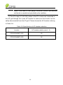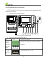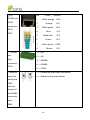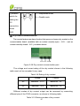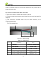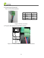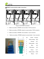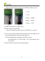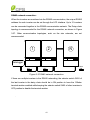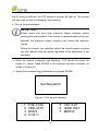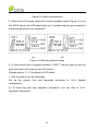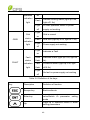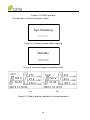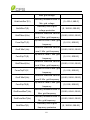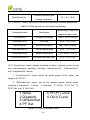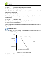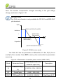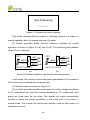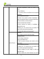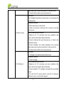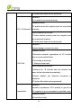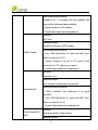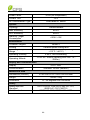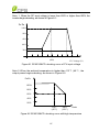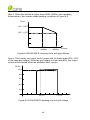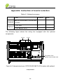
1
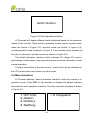
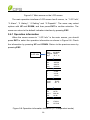
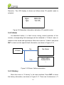
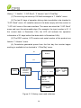
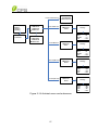
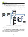
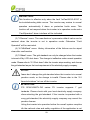
物料: CPS SCA23/28KTL-DO/US-480 英文版说明书 料号: 9.0020.0119B0 纸张大小: 大 32 开 封面制作要求: 200g 铜版纸附亚膜封面彩色印刷 内页制作要求: 70g 除静电双胶纸黑白印刷 CPS SCA Series Grid-tied PV Inverter CPS SCA23/28KTL-DO/US-480 Installation and Operation Manual Ver 1.1 CHINT POWER SYSTEMS AMERICA CO., LTD. Address: 700 International Parkway Suite 102 Richardson TX 75081 Web: www.chintpower.com/na Email: [email protected] Service Hotline: 855-584-7168 SHANGHAI CHINT POWER SYSTEMS CO., LTD. All rights reserved. Specifications and designs included in this manual are subject to change without notice. CHINT POWER 2013/10-MKT PN: 9.0020.0119B0 Table of Contents Before You Start… ...................................................................................... 1 Chapter 1 IMPORTANT SAFETY INSTRUCTIONS .................................... 2 Chapter 2 Overview .................................................................................... 5 2.1 Inverter for grid-tied PV systems ................................................... 5 2.2 Product features ............................................................................ 5 2.3 Product protection functions .......................................................... 6 2.4 Circuit structure design .................................................................. 6 2.5 Appearance Description ................................................................ 7 Chapter 3 Installation ................................................................................. 9 3.1 Recommendations before installation .......................................... 11 3.2 Mechanical installation ................................................................ 12 3.3 Electrical installation .................................................................... 22 3.3.1 DC connection ..................................................................... 24 3.3.2 AC and ground connection .................................................. 28 3.3.3 Communication connection ................................................. 33 Chapter 4 Commissioning ....................................................................... 42 4.1 Commissioning Checklist ............................................................ 42 4.1.1 Mechanical installation ........................................................ 42 4.1.2 Cable connections ............................................................... 42 4.1.3 Electrical check.................................................................... 42 4.2 Commissioning steps .................................................................. 42 Chapter 5 User Interface .......................................................................... 45 5.1 Description of LCD panel ............................................................ 45 5.2 Operation state ............................................................................ 47 5.3 Interface types ............................................................................. 47 5.4 Menu functions ............................................................................ 49 5.4.1 Operation information .......................................................... 50 5.4.2 Alarm ................................................................................... 51 5.4.3 History .................................................................................. 51 5.4.4 System configuration ............................................................ 53 5.4.5 Power dispatch..................................................................... 55 5.4.6 AutoTest ............................................................................... 56 5.4.7 System protection parameters setup .................................... 58 5.4.8 System control parameters .................................................. 60 Chapter 6 Operation .................................................................................. 67 6.1 Start-up ........................................................................................ 67 6.2 Shut-down .................................................................................... 67 6.3 Operation mode ........................................................................... 67 6.4 Grid-tied power generation .......................................................... 69 Chapter 7 Maintenance and De-installation ............................................ 71 7.1 Fault shut down and troubleshooting ........................................... 71 7.1.1 LED fault and troubleshooting .............................................. 71 7.1.2 LCD fault and troubleshooting .............................................. 71 7.2 Product maintenance ................................................................... 79 7.2.1 Check the electrical connection............................................ 79 7.2.2 Clean the air vent filter ......................................................... 79 7.2.3 Replace cooling fans ............................................................ 79 7.2.4 Replace the inverter ............................................................. 82 7.3 De-installing the inverter .............................................................. 84 Chapter 8 Technical Data .......................................................................... 85 Chapter 9 Limited Warranty ...................................................................... 89 Appendix: Instruction of inverter selection ............................................ 90 Before You Start… This manual contains important information regarding installation and safe operation of this unit. Be sure to read this manual carefully before using. Thank you for choosing this CPS Grid-tied PV Inverter. This PV Inverter is a high performance and highly reliable product specifically designed for the North American Solar market. If you encounter any problems during installation or operation of this unit, first check the user manual before contacting your local dealer or supplier. This user manual is applicable for the following 2 models: CPS SCA23KTL-DO/US-480 and CPS SCA28KTL-DO/US-480. Instructions inside this user manual will help you solve most installation and operation difficulties. Contact your local supplier if the problem still exists. Please keep this user manual on hand for quick reference. 1 Chapter 1 IMPORTANT SAFETY INSTRUCTIONS (SAVE THESE INSTRUCTIONS) Please read this user manual carefully before product installation. CPS reserves the right to refuse warranty claims for equipment damage if the user fails to install the equipment according to the instructions in this manual. Warnings and symbols in this document DANGER: DANGER indicates a hazardous situation which, if not avoided, will result in death or serious injury. WARNING: WARNING indicates a hazardous situation which, if not avoided, could result in death or serious injury. CAUTION: CAUTION indicates a hazardous situation which, if not avoided, could result in minor or moderate injury. NOTICE: NOTICE indicates a hazardous situation which, if not avoided, could result in equipment working abnormally or property loss. INSTRUCTION: INSTRUCTION indicates important supplementary information or provides skills or tips that can be used to help you solve a problem or save you time. 2 Markings on the product HIGH VOLTAGE: The product works with high voltages. All work on the product must only be performed as described in this document. HOT SURFACE: The equipment is designed to meet international safety standards, but surfaces can become hot during operation. Do not touch the heat sink or peripheral surfaces during or shortly after operation. EARTH GROUND: This symbol marks the location of grounding terminal, which must be securely connected to the earth through the PE (protective earthing) cable to ensure operational safety. WARNING: All the installation and wiring connections should be performed only by qualified technical personnel. Disconnect the inverter from PV modules and the Power Grid before maintaining and operating the equipment. DANGER: Please disconnect the inverter from AC grid and PV modules before opening the equipment. Make sure hazardous high voltage and energy inside the equipment has been discharged. Do not operate or maintain the inverter until at least 5 minutes after disconnecting all sources from DC and AC sides. 3 NOTICE: This inverter is designed to connect AC power only to the public grid. Do not connect the AC output of this equipment directly to any private AC power equipment. CAUTION: CPS SCA23/28KTL-DO series inverter is approx 55kg (≈122 pounds). Please ensure the mounting is properly installed before hanging the the inverter on the bracket. INSTRUCTION: Please check with your local electricity supply company before selecting the grid standard. If the inverter is operated with a wrong grid standard, the electricity supply company may cancel the operation license. Putting the inverter into operation before the overall system complies with the national rules and safety regulation of the application is not permitted. 4 Chapter 2 Overview 2.1 Inverter for grid-tied PV systems CPS SCA23/28KTL-DO/US-480 series inverter is suitable for use with commercial and large scale PV grid-tied systems. The system is generally made up of PV modules, DC power distribution equipment, PV inverter and AC power distribution equipment (Figure 2-1). The inverter converts the DC from PV modules to AC with the same frequency and phase as the AC grid. All or part of the AC power is supplied to local loads, and the surplus power is supplied to the electricity grid. DC power AC power distribution distribution equipments equipments Bidirectional electric meter AC Grid Figure 2-1 Grid-tied PV system 2.2 Product features High conversion efficiency:Advanced 3-level conversion technology; Max. efficiency: 98.4%;CEC efficiency: 98% Strong grid adaptability: 7 grid standards applicable; Reactive power adjustable; PF value:±0.8, Remote Curtailment Flexible communication: Supports standard modbus communications to rd ensure compatibility with 3 party monitoring and control systems Wide DC input voltage range:Operating DC Input Voltage Range: 300-900Vdc; Max DC input voltage: 1000V Long service life: Uses thin-film capacitors to extend inverter’s service life 5 2 MPPTs: Dual and independent MPPT (Maximum Power Point Tracking) enable maximum design flexibility and optimize energy harvest over the life of the system High protection degree: NEMA 4 protection degree meets the needs of both indoor and outdoor use; Intelligent Integration: Embedded DC/AC switches and up to 8 fused string inputs eliminates the need for external combiner boxes and simplifies installation. 2.3 Product protection functions Polarity reverse protection of DC input Short circuit protection DC input insulation against ground monitoring AC output voltage and frequency monitoring Leakage current against ground monitoring Monitoring of DC injection from AC output Anti-islanding protection Input and output over-voltage protection Input over-current protection Environmental temperature monitoring Module temperature monitoring 2.4 Circuit structure design The basic schematic diagram of CPS SCA23/28KTL-DO/US-480 series inverter is shown in Figure 2-2. The input of PV modules passes through surge protection circuitry, DC EMI wave filter, and the front-end boost circuitry to achieve maximum power tracking and boost up voltages. The output of the inverter converts the DC voltage to 3-phase AC voltage. The high frequency AC components are 6 removed with a wave filter. Then the 3-phase AC voltage is passed through two-stage relays and EMI wave filter to produce high quality AC power. PV FUSE Clip Input ( No FUSE) PV1+ PV1+ PV1+ PV1+ DC Switch MPPT1 PV1+ PV1- AC Switch PV1PV1PV1PV1- AC Output N L1 L2 MPPT2 PV2+ PV2+ PV2+ PV2+ L3 PV2+ PV2- Three level inverter PV2PV2PV2PV2- PE AFD Figure 2-2 Schematic diagram of CPS SCA23/28KTL-DO series inverter 2.5 Appearance Description 3 4 1 4 2 9 8 5 6 7 Figure 2-3 Appearance sketch of CPS SCA23/28KTL-DO series inverter 7 Main items of the inverter: 1) Main housing of the inverter 2) Wiring box of the inverter 3) Mounting bracket 4) External cooling fans 5) LED indication lights 6) LCD display 7) Key buttons 8) DC switch: DC power on/off 9) AC switch: AC power on/off 8 Chapter 3 Installation Below is the installation procedure for the inverter. Please read carefully and install the product step-by-step. Before installation, please check that the following items are included in the package: Table 3-1 Main items No. (1) (2) Item Main housing of the PV inverter Wiring box of the PV inverter Q’ty Note 1 1 Upon which inverter is hung and (3) Mounting bracket 1 (4) User manual 1 Installation and operation manual (5) Warranty card 1 For maintenance and repair (6) Packing list 1 (7) Accessory kit 1 mounted onto a wall Contains all necessary accessories The (7) Accessory kit contains items listed below: Table 3-2 Accessories No. Item Q’ty Note 9 (1) M8 Expansion tubes 8 For mounting bracket (2) M8×25 assembling bolts 8 For mounting bracket (3) M6X12 screw 6 (4) M5X10 screw 8 (5) M5 flange nut 2 (6) Lifting eye nut M10 2 For lifting the main housing (7) OT type terminal 2 For ground connection (8) (9) Pre-insulated end ferrule for AC side Pre-insulated ferrule for DC side end For wiring box and main housing; 2 spare parts For mounting bracket and inverter, external ground connection For internal ground stud connection; 1 spare part For AC output and ground cables, 2 8 spare parts 20 For DC input cables, 4 spare parts For RS485 or Ethernet (10) RJ45 connecter 4 (11) Jumper busbar 1 (12) 5 pin connector 1 For RS485 communication (13) 3 pin connector 1 For dry contact communication communication, 2 spare parts For parallel mode cable connection (positive pole) INSTRUCTION: The items in the accessory kit table above are for the standard configuration. The accessories may vary if optional parts are 10 purchased. 3.1 Recommendations before installation Check that the product environmental specifications (protection degree, operating temperature range, humidity and altitude, etc) meet the requirements of the specific project location; Make sure that the power grid voltage is within normal range; Ensure that the local electricity supply authority has granted permission to connect to the grid; Installation personnel must be qualified electricians or people who have received professional training; Sufficient space is provided to allow the inverter cooling system to operate normally; Install the inverter away from flammable and explosive substances; Avoid installing the inverter in locations that exceed the temperature limits specified in the inverter data sheet to limit undesirable power loss; Do not install the inverter near the electromagnetic source which can compromise the normal operation of electronic equipment; 11 3.2 Mechanical installation 1) Dimensions Figure 3-1 Dimensions of CPS SCA23/28KTL-DO series inverter 12 2) Installation method (see Figure 3-2): Make sure that the mounting structure (wall, rack, etc) is suitable to support the inverter weight. Follow the mounting guidelines below: (a) If the location permits, install the inverter vertically. (b) If the inverter cannot be mounted vertically, it may be tilted backward by no lower than 15 degrees from horizontal. (c) Do NOT mount the inverter leaning forward. (d) Do NOT mount the inverter in a horizontal position (<15 degrees). (e) Do NOT mount the inverter upside down. (a) (b) (c) (d) Figure 3-2 Mount the inverter correctly 13 (e) 3) Installation space requirement (see Figure 3-3): The distances between the inverters or the surrounding objects should meet the following conditions: NOTICE: The spacing between two adjacently mounted inverters should be ≥1000mm (39.4 inches). Ensure that the air space around the inverter is well ventilated. ≥300mm (11.8in.) ≥500mm (19.7in.) ≥1000mm (39.4in.) ≥600mm (23.6in.) Figure 3-3 Inverter mounting dimensions 4) Mount the inverter onto the bracket (1) Mark the 8 holes on the bearing surface for mounting the bracket as shown in Figure 3-4; 14 Figure 3-4 Dimensions of holes on the bearing surface (2) Drill holes at the marked positions with a 10mm (0.4in.) drill and put the M8 expansion tubes① into the holes; Fasten the mounting bracket② with the M8x25 assembling bolts③ in the accessory kit. Tool: Electric drill (Ф10mm/0.4in. head), No. 13 wrench 15 1 2 3 Figure 3-5 Secure the mounting bracket (3) Hang the inverter onto the mounting bracket as shown in Figure 3-6 and Figure 3-7; Lift mounting: Take out the lifting eye nut M10 (2pcs) from the accessory kit, and screw them on the bolts at the top of the inverter. Use sling rope or bar (inserted through both lifting eye nuts) to lift the inverter onto the bracket. The minimum angle between the two sling ropes should be less than 90 degrees. Manual mounting: Two people grab the handle positions marked in Figure 3-7, and mount the inverter onto the bracket. CAUTION: The main housing of the CPS SCA23/28KTL-DO series inverter is about 46.5kg (≈102.5 pounds). Please ensure the mounting is properly installed before hanging the the inverter on the bracket. It is recommended to have at least 16 2 people to mount the inverter due to the weight of the equipment. Figure 3-6 Mount the main housing on the bracket by lifting Figure 3-7 Position of grab handle 17 (4) Install the wiring box ① Remove the cover plate at the bottom of the main housing. (see Figure 3-8) Tool: No.2 Phillips head screwdriver Figure 3-8 Cover plate of the main housing ② Remove the cover board at the top of the wiring box (see Figure 3-9) Figure 3-9 Cover board of the wiring box Save the cover board and screws, and fix the board on the left side of the wiring box after the wiring box is attached to the inverter housing (see step 6, Figure 3-12) 18 Tool: No.2 Phillips head screwdriver ③Insert the wiring box to the main housing, and use M6x12 screws (4pcs) to attach the wiring box to the inverter housing. (see Figure 3-10) Tool: No. 10 Wrench, torque value of 2.8N.m Figure 3-10 Installation of the wiring box CAUTION: The total weight of the CPS SCA23/28KTL-DO series inverter is about 55kg (≈122 pounds). Please ensure the mounting is properly installed before hanging the the inverter on the bracket. (5) Attach the main housing and the wiring box to the mounting bracket with the M5x10 bolts (6 pcs). (see Figure 3-11) Tool: No.2 Phillips head screwdriver, torque value of 1.6N.m 19 Figure 3-11 Fix the main housing and wiring box on the bracket (6) Attach the cover board shown in Figure 3-10 to the left side of the wiring box. (see Figure 3-12) Tool: No.2 Phillips head screwdriver, torque value of 1.2N.m Figure 3-12 Attach the cover board to the left side of the wiring box 20 (7) Optional - Install an anti-theft padlock when the installation is complete. The anti-theft padlock is used to prevent the inverter from being stolen when the equipment is installed outdoors. You can lock the inverter on the bracket, as shown in Figure 3-13: Figure 3-13 Location of the anti-theft padlock The anti-theft padlock should meet the requirement of the dimensions shown in Figure 3-14: B C A Recommended lock size: A: Ф3~6mm B: 20~50mm C: 20~50mm Figure 3-14 The dimensions of anti-theft padlock 21 3.3 Electrical installation The connection interface of CPS SCA23/28KTL-DO series inverter: DC INPUT 1 DC INPUT 2 AC OUTPUT COMM. PORT ANT. 4 5 WARNING: High touch current . Earth connection essential before connecting supply. 1 1 2 3 Figure 3-15 External connection ports PV1 + 6 PV1 6 PV2 + 6 PV2 6 L1 L2 L3 N 7 8 Figure 3-16 Internal connection points 1. Knockout holes for DC input cable, 1-1/4” or 1” 2. Knockout hole for AC output cable, 1-1/4” or 1” 3. External ground connection point 4. Knockout hole for communication cable, 3/4” 5. Wireless communication antenna port (For optional Zigbee communication) 6. DC input terminal block 7. AC output terminal block 8. Internal ground connection point & grounding studs 22 Choose the cables for inverters according to the following configuration table: Table 3-3 Cables specifications Position DC input (﹢/﹣) length (m) #12~10AWG PV cable Cable #10~6AWG AC Max. cable Cable 61 (#10AWG) #8AWG output cable 32 (#8AWG) recommended (L1/L2/L3/N/PE) RS485 UTP CAT-5e communication communication or cable 3106A) 23 3x#22~18AWG (eg. Belden 1200 3.3.1 DC connection 1) Working mode CPS SCA23/28KTL-DO series inverter has two PV input sections: DC Input-1 and DC Input-2. These two sections can work under “Parallel mode” or “Independent mode”. (see Figure 3-17) Under Parallel mode, the two PV input sections share one MPP Tracker; Under Independent mode, each PV input section works with one MPP Tracker. Inverter Inverter DC Input-1 n1 DC Input-1 DC Input-2 n2 n3 n1=n2 =n3=n4 DC Input-2 n1 n2 n1=n2 n4 Figure 3-17(a) Parallel mode n3 n4 n3=n4 Figure 3-17(b) Independent mode Table 3-4 DC input power specification Inverter model Max. DC input power Rated DC input power of each input section SCA23KTL-DO 24kW 12kW SCA28KTL-DO 29kW 14.5kW Remarks: The standard configuration is “independent mode”. If it needs to switch to the “Parallel mode”, please take the following steps to change the internal configuration: 1. Remove the cover of the wiring box. (see Figure 3-23) 2. Use No.2 Phillips head screwdriver to remove the wire terminals from the J9 & J10 terminal blocks on the fuse board. 3. Put the jumper busbar attached in the accessory kit on the J9 & J10 24 terminal blocks, and tighten the wire terminals back on the terminal blocks with a torque value of 1.2N.m. Figure 3-18 Internal configuration of parallel mode 4. Set the selector switch on the LCD board (see Figure 3-19) to parallel mode. PAR IND S401 Communication board 25 Figure 3-19 Location of the PV connection mode selector switch Selector switch for 1-----independent mode PV connection 2-----parallel mode mode 2) DC fuse selection CPS SCA23/28KTL-DO inverters can be equipped with typical 12A (23kW Inverter) and 15A (28kW Inverter) DC fuses. Customers must verify that the appropriate fuses are used depending on the actual configuration PV strings. 1) Each independent string of DC input from the PV strings needs fuse protection. 2) The rated voltage of fuse should be higher than the Max. Voc of each PV string. 3) In order to keep the output power normal, the rated current of fuse is generally larger than the 1.5 × Max. output current from the PV strings. 4) In order to protect the PV strings, the rated current of fuse should NOT be larger than the sum of the Isc of any two of the PV strings. Make sure the rated current of fuse is as small as possible on the condition of normal output power. The following table lists the recommended fuse type, specifications and number under the rated voltage and power range of 8 strings of PV panels. Table 3-5 Recommended fuses Rated Rated current voltage 0SPF012.T 12A 1000V 16 0SPF015.T 15A 1000V 16 Brand Type SCA23KTL-DO Littelfuse SCA28KTL-DO Littelfuse 26 Number 3) DC cable connection To ensure the optimum performance of the inverter, please read the following guidelines before DC connection: (a) Confirm the DC configuration referring to Table 3-5 and ensure that the maximum open circuit voltage of the PV modules is lower than 1000 Vdc under any conditions; (b) Confirm that the PV strings for each MPPT of the inverter are of the same type and specification before connection. The number, orientation, and tilt of PV strings may differ for different applications. (c) Check the polarity (Figure 3-20) before plugging the DC connectors with the cables of PV strings according to the following steps: i. Use a multi-meter to measure the PV strings’ cable ends and check the polarity. ii. The positive (+) terminal of cable should match the positive (+) terminal of inverter’s DC input. iii. The negative (-) terminal of cable should match the negative (-) terminal of inverter’s DC input. NOTICE: It is important to use a multi-meter to check the polarity of DC input cables to avoid any risk of reverse polarity. Figure 3-20 Polarity check (d) Knock out the holes of the DC side and plug the suitable conduits of 27 1-1/4 or 1 inch through the holes. Then put the cables through the conduits inside the wiring box. (e) Crimp the DC cables with the attached pre-insulated end ferrule (16Pcs) by using the the crimping pliers. (see Figure 3-21) Tools: Diagonal pliers, wire stripping pliers, crimping pliers Figure 3-21 Set up the DC input cables (f) Connect the crimped DC cables to the terminal block on the circuit board and fasten the screws, as shown in Figure 3-22: Tools: 4mm (0.16in.) flat screwdriver Torque value: 1.2 N-m PV1 + PV1 PV2 + PV2 L1 L2 L3 N Figure 3-22 Connection of DC input cables 3.3.2 AC and ground connection The following describes how to connect the AC output and ground cables between the inverter and the AC grid: 1) Use the 3mm (0.12in.) Hex screwdriver to screw off the 4 screws on the wiring box and take off the cover. (see Figure 3-23) 28 Figure 3-23 Take off the cover of the wiring box 2) Knock out the holes of the DC side and plug the suitable conduits of 1-1/4 or 1 inch through the holes. Then put the cables through the conduit inside the wiring box. 3) The inverter supports 3 kinds of cable connection on the AC side depending on the grouding connection method. The cable set-up procedures are illustrated below. Table 3-6 Necessary tools for cable set up No. Tools 1. 4mm (0.16in.) flat screwdriver 2. 8mm hex socket wrench 3. Diagonal pliers 4. Wire stripping pliers 5. Crimping pliers Table 3-7 Torque value AC output terminal block 1.2 N-m Internal grounding bar 1.6 N-m Internal grounding stud 1.6 N-m 29 External grounding point 1 2 L1 L2 L3 N 1.6 N-m 3 L1 L2 L3 N L1 L2 L3 N AC OUTPUT COMM. PORT WARNING: High touch current . Earth connection essential before connecting supply. Figure 3-24 AC output and ground cable connection (1) Connect the AC (L1, L2, L3, N) cables to the terminal block and the st ground cable to the grounding bar. (see the 1 graph in Figure 3-24) Set up the cables referring to Figure 3-25. Pre-insulated end ferrule 5pcs Core wire Pre-insulated end ferrule Figure 3-25 AC output and ground cable set up (2) Connect the AC (L1, L2, L3, N) cables to the terminal block and use the OT type terminal to connect the ground cable to the internal grounding stud inside the wiring box. (see the 2 3-24) Set up the cables referring to Figure 3-26. 30 nd graph in Figure Pre-insulated end ferrule 4pcs OT type terminal,1pcs Core wire Pre-insulated end ferrule Core wire OT type terminal Figure 3-26 AC output and ground cable set up (3) Connect the AC (L1, L2, L3, N) cables to the terminal block and use the OT type terminal to connect the ground cable to the external rd grounding point at the bottom of the wiring box. (see the 3 graph in Figure 3-24) Set up the cables referring to Figure 3-27. Pre-insulated end ferrule 4pcs Core wire Pre-insulated end ferrule Ground wire OT type terminal,2pcs Figure 3-27 AC output and ground cable set up INSTRUCTION: The attached pre-insulated end ferrules match with the #8AWG 31 cables. If the cable of other gauge is selected, different pre-insulated end ferrule is needed and provided by the installers. 4) The AC output (L1/L2/L3/N) cables of the PV inverter are connected to the AC grid through the 4 pole AC breaker to make sure the inverter can be safely disconnected from the AC grid. Please choose the AC breaker referring to Table 3-8: Table 3-8 Specification of AC breaker selection Inverter AC breaker rated current(A) CPS SCA23KTL-DO 50 CPS SCA28KTL-DO 64 32 3.3.3 Communication connection CPS SCA23/28KTL-DO series inverter supports industry standard Modbus RS485 communication. 1. Communication board description PAR IND S401 ON OFF S402 Communication board P203 P204 P207 P208 P205 3 4 Figure 3-28 Communication board 2. Connectors and communication cards Item Picture ① Dry Configuration description Please see the section after the table for detailed contact information. communic ation port P205 ② USB N.O. N.C. COM Firmware upgrade via USB disk port P207 33 ③/④ No. RS485 port 1 (RJ45 2 connector) 3 Colour Function White orange Orange White green 485+ N.C 485- P203, P204 4 5 Blue White blue 6 7 Green White brown 8 Brown ⑤ RS485 1 -----NC port 2 -----NC (5pin 3 -----RS485+ connector) N.C. N.C. N.C. COM N.C 4 -----RS485- P208 5 -----COM ⑥Selector 1-----Disable the termination resistance switch for 2-----Enable the terminal resistor setting the 120Ω terminal resistor of the RS485 communic ation S402 34 ⑦Selector 1-----Independent mode switch for 2-----Parallel mode setting the PV connection mode S401 ① Dry contact communication: The inverter features an alarm function that opens or closes a dry contact on the communication board. (available both as contact normally open – N.O. – and as contact normally closed – N.C.), as shown below: N.O. N.C. COM Figure 3-29 Dry contact communication port The voltage and current rating of the dry contact shown in the following table must not be exceeded in any case. Table 3-9 Rating of dry contact Voltage Current AC Maximum 277 V Maximum 3 A DC Maximum 30 V Maximum 1 A Different modes of dry contact output can be accessed by connecting different pins of the P205 connector, as shown in following table. Table 3-10 Working modes of dry contact 35 Dry contact communication Status in fault Status without fault port condition condition P205: N.O. — COM Closed Open P205: N.C. — COM Open Closed Connection Plan: You can connect a LED or other loads to indicate the operational status of the inverter, as shown in the following figure: (or L + Line circuit Breaker( 3 A) (or L N) - + N) - Line circuit Breaker( 3 A) COM COM N.C. N.C. N.O. N.O. COM COM N.C. N.C. N.O. N.O. COM COM N.C. N.C. N.O. N.O. Light on in trouble free operational Fault In operation In operation Light on in error Figure 3-30 Schematic diagram of dry contact communication If you connect the contact port to the power distribution grid, you must 36 install an individual miniature circuit-breaker between the dry contact and the power distribution grid. Dry contact communication cable connection: a.) Knock out the holes for suitable cable conduits of 3/4 inch. b.) Put the dry contact communication cable through the cable conduit and inside the wiring box. c.) Use double-layer insulated cables. Strip the cables according to the following requirements. Tool: Wire stripping pliers D A L2 L1 Figure 3-31 Wire stripping Table 3-11 Cable set-up Position Description Value Cable type Double-layer insulated cable D Outer diameter 4.5 mm~ 6 mm A Cross-section area of conductor 0.2 mm²~ 0.75 mm² L1 Length of stripped outer wire skin Maximum 15mm L2 Length of stripped inner wire skin Maximum 7 mm 37 d.) Connect wires to the terminal. Tool: 2 or 2.5mm flat screwdriver No. Cable Color Function 1 Red N.O. 2 Blue N.C. 3 Green COM Figure 3-32 Wire connection e.) Plug the cable terminal into the P205 connector. Figure 3-33 The dry contact communication cable connection 38 ② RS485 communication cable connection: 1 2 3 4 Figure 3-34 RS485 connection 1. Cable connection of RS485 communication: RJ45 connector 2. Cable connection of RS485 network communication: RJ45 connector 3. Cable connection of RS485 communication: 5 pin connector 4. Cable connection of RS485 network communication: 5 pin connector No. 1 2 3 4 5 6 7 8 39 Colour Function White orange Orange White green Blue White blue Green White brown Brown 485+ N.C 485N.C. N.C. N.C. COM N.C Figure 3-35 Crimp RJ45 connector on the RS485 and Ethernet cable 1 -----NC 2 -----NC 3 (Red)--------RS485+ 4 (Blue) -------RS4855 (Green)----- COM (1) (2) (1) RS485 communication of single inverter (2) RS485 network communication Figure 3-36 Fasten the cable terminal on the RS485 5 pin connector a.) Put the communication cable through the conduits inside the wiring box, and crimp the cable as shown in Figure 3-35 and Figure 3-36. Tools: Wire stripping pliers, crimping pliers (for RJ45 connector) Wire stripping pliers, 2 or 2.5mm (0.08in. or 0.1in.) flat screwdriver (for 5 pin connector) b.) Plug the crimped connector into the corresponding port. 40 RS485 network connection: When the inverters are monitored via the RS485 communication, the unique RS485 address for each inverter can be set through the LCD interface. Up to 31 inverters can be connected together in the RS485 communication network. The Daisy-chain topology is recommended for the RS485 network connection, as shown in Figure 3-37. Other communication topologies, such as the star networks, are not recommended. 1 2 N Datalogger S402 OFF S402 OFF S402 ON Figure 3-37 R485 network connection If there are multiple inverters in the RS485 networking, the selector switch S402 of the last inverter in the daisy chain should be in ON position to have the 120ohm terminal resistor enabled while keeping the selector switch S402 of other inverters in OFF position to disable the terminal resistor. . 41 Chapter 4 Commissioning WARNING: Please follow the guidelines below before on-grid operation to eliminate possible dangers to ensure safety. 4.1 Commissioning Checklist 4.1.1 Mechanical installation Make sure that the mounting bracket is secure and all the screws have been tightened to the specified torque values. (Please refer to 3.2 Mechanical installation) 4.1.2 Cable connections Make sure that all cables are connected to the right terminals. The appropriate cable management is important to avoid physical damage. The polarity of DC input cables should be correct and the DC Switch should be on “OFF” position. (Please refer to 3.3 Electrical installation) 4.1.3 Electrical check Make sure that the AC circuit breaker is appropriately sized. Test whether the AC voltage is within the normal operating range. Make sure the DC open circuit voltage of input strings is less than 1000V. 4.2 Commissioning steps Complete the checklist above before commissioning the inverter as follows: 1.) Turn on the AC circuit breaker. 2.) Turn on the DC circuit breaker. (Skip these two steps if there are no circuit breakers.) 3.) Switch the DC Switch to the “ON” position. When the energy supplied by 42 the PV array is sufficient, the LCD screen of inverter will light up. The inverter will then start up with the message “sys checking”. 4.) Set up the grid standard: INSTRUCTION: Please check with your local electricity supply company before selecting the grid standard. If the inverter is operated with a wrong grid standard, the electricity supply company may cancel the operation license. Putting the inverter into operation before the overall system complies with the national rules and safety regulation of the application is not permitted. When the inverter completes “sys checking”, LCD shows the screen as Figure 4-1 below. Press ENTER to the standard selection interface, as shown in Figure 4-2. Select the corresponding grid standard and press ENTER. Set Standard! Figure 4-1 Set up grid standard →1 2 3 4 5 CEI 0-21 6 IEEE1547 7 BDEW VDE-0126 VDE-4105 G59/2 C10/11 43 Figure 4-2 Select grid standard 5.) When the LCD screen shows the normal operation status (Figure 4-3) and the “RUN” light on the LED panel lights up, it indicates that the grid connection and power generation are successful. PV1 725 V 38.5A PV2 720 V 31.9A 277 27.9 223.2 08/12 13:10:05 277 22.9 183.7 08/12 13:10:10 (a) (b) Figure 4-3 Normal operation status 6.) If the inverter fails to operate normally, “FAULT” light will light up and the fault information will show on the LCD screen. (Please refer to 7.1.2 Troubleshoot LCD faults) 7.) Set up system time and language Set up the system time and language according to “5.4.4 System configuration”. 8.) To check the real time operation information, you can refer to “5.4.1 Operation information”. 44 Chapter 5 User Interface 5.1 Description of LCD panel The inverter’s LCD panel mainly consists of LCD screen, LED indicator lights, buzzer and 4 keys, as shown in Figure 5-1. POWER RUN GRID FAULT Figure 5-1 LCD panel Interpretation for the indicator lights is shown in Table 5-1 and function of the keys is shown in Table 5-2. Table 5-1 LED Indication LED light Name Status Light Working POWER on Energized (control panel starts to work) power light Light off RUN Indication Grid-tied Light Power supply not working In grid-tied power generation state 45 operation on indication light Flash Light off Light Grid GRID status indication light on Flash Light off Light on FAULT Derated running status (light up 0.5s, light off 1.6s) In other operation status or power supply not working Grid is normal Grid fault (light up 0.5s, light off 1.6s) Power supply not working Indicates a Fault Fault Slow Indicates Alarm (light up 0.5s, light off status flash 2s) indication Fast Protective action (light up 0.5s, light light flash off 0.5s) Light off No fault or power supply not working Table 5-2 Definition of the keys Key Description Definition of function Escape key Back/end/mute Enter key Confirm entering the menu/confirm set value/Switch to parameter setting mode Up Page up in selection menu/+1 when setting parameters 46 Down Page down in selection menu/-1 when setting parameters 5.2 Operation state Table 5-1 indicates the definitions of LED, i.e. indicates the information of the inverter’s operation state. It indicates that the system is energized and under DSP control when “POWER” lights up. “RUN” will light up when the inverter detects that the grid connection conditions meet the requirements and power is fed into the grid. “RUN” will blink if the grid is in de-rated running state during the period of feeding power into the grid. “GRID” will light up when the grid is normal during the operation of the inverter. Otherwise, “GRID” will blink until the grid restores to normal. “FAULT” will blink quickly as a fault (except grid fault) occurs. “FAULT” will not light out until the fault is eliminated. The light will blink slowly when an alarm occurs. “FAULT” remains illuminated when an internal fault occurs. The buzzer will give an alarm if a fault (involving power grid fault) occurs. 5.3 Interface types Users can perform the corresponding operations with the 4 function keys according to the indications of the LCD display. (1) The LCD interface starts with the company logo once the system is energized, as shown in Figure 5-2. 47 Figure 5-2 LOGO interface (2) Indication of inverter operation mode: Sys.Checking >>>>>> Figure 5-3 Inverter system check ongoing Standby >>>>>> Figure 5-4 Inverter system in standby mode PV1 725 V 38.5A PV2 720 V 31.9A 277 27.9 223.2 08/12 13:10:05 277 22.9 183.7 08/12 13:10:10 (a) (b) Figure 5-5 Default display interface for normal operation 48 GridV.OutLim Figure 5-6 Fault indication interface LCD screen will display different mode interfaces based on the operation modes of the inverter. There are four operation modes: startup system check mode (as shown in Figure 5-3), stand-by mode (as shown in Figure 5-4), normal operation mode (as shown in Figure 5-5, the switching time between (a) and (b) is 5 seconds), and fault mode (as shown in Figure 5-6). The default indication interface mainly indicates PV voltage, PV current, grid voltage, instant power, daily generated power and time information under normal operation. The fault information of the most recent / current fault will be indicated on the LCD screen when the inverter is in fault mode. 5.4 Menu functions LCD screen displays “default indication interface” when the inverter is in operation mode. Press ESC in this interface to escape the default interface and enter the main operation interface. The main operation interface is shown in Figure 5-7. 1 2 3 4 →5 Dispatch OP.Info Alarm History Setting 49 Figure 5-7 Main menus on the LCD screen The main operation interface of LCD screen has 5 menus, i.e. “1 OP. Info”, “2 Alarm”, “3 History”, “4 Setting” and “5 Dispatch”. The users may select options with UP and DOWN, and then press ENT to confirm selection. The users can return to the default indication interface by pressing ESC. 5.4.1 Operation information When the cursor moves to “1 OP. Info” in the main screen, you should press ENT to select the operation information as shown in Figure 5-8. Check the information by pressing UP and DOWN. Return to the previous menu by pressing ESC. EDay 23.5kWh PDayPk 19kW DayT 12 .1 h 1 OP.Info Uab Ubc Uca Freq 400.2V 400.9V 399.7V 60.0Hz Ia Ib Ic 13.9A 14.1A 13.1A Tmod Tamb 78.2C 50 C Upv 1 Ipv1 Upv 2 Ipv2 360.0V 14.7A 360.4V 14.3A Sac Pac 17KVA 16.7kW Figure 5-8 Operation information indication (PV independent mode) 50 Remarks:The LCD display is shown as follows when PV parallel mode is selected. Upv Ipv 360.0V 14.7A Figure 5-9 Operation information indication (PV parallel mode) 5.4.2 Alarm As described before, if a fault occurs during normal operation of the inverter, corresponding fault messages will be indicated in “2 Alarm” menu in addition to the sound and light alarms. Move the cursor to “2 Alarm” and press ENT to check out the specific fault information, as shown in Figure 5-10. 2 Alarm No No Alarm Yes EepromErr Protect0010 … Figure 5-10 Alarm / failure information 5.4.3 History Move the cursor to “3 History” in the main interface. Press ENT to check the history information, as shown in Figure 5-11. There are 4 submenus in “3 51 History”: “1 HistErr”, “2 OP. Recd”, “3 Version” and “4 TotalTag”. (1) The error log can store up 100 fault messages in “1 HistErr” menu. (2) The last 21 days of operation history data is available to be checked in “2 OP. Recd” menu. All variable names in the data comply with the content in “1 OP. Info” menu of the main interface. The users can select the “2 OP. Recd” menu and input the retraceable days (For example, the input number is 21. If the current date is December 15th, the LCD will indicate the operation information of 21 days before that date which is November 24th). (3) The DSP version, LCD version and serial number of the product are listed in “3 Version” menu. (4) Cumulative generated power from the first day the inverter began working is available to be checked in “4 TotalTag” menu. No NoError 1.St2010.12.15 20:50 SPI Error 2.Ed2010.12.15 20:59 SPI Error … Yes 3 History 1 HistErr 2 OP.Recd 3 Version →4 TotalTag Pls input date ←2→ ß—12/15 DSPVer. 0.01 LCDVer. 0.01 Serial No. 10731220003 TotalTag(KWh) 2123.5 Figure 5-11 History menu and submenu 52 EDay 123.5KWh PDayPk 20.0KW DayT 7.0h 5.4.4 System configuration Move the cursor to “4 Setting” in the main interface. Press ENT to enter the password: UP -> DOWN -> UP -> DOWN. Press ENT to confirm, and set the current system parameters, as shown in Figure 5-12. There are 7 submenus in “4 Setting”: “1 ON/OFF”, “2 Language”, “3 Buzzer”, “4 SysTime”, “5 Commun.”, “6 OtherCmd” and “7 NetConfig”. → ON OFF ON State 4 Setting 1 ON/OFF 2 Language 3 Buzzer →4 SysTime 5 Commun 6 OtherCmd 7 NetConfig → 中文 English EnglishVer. → Francaise Deutsch EnglishVer. KeyBeep Enabled AlarmBeep → Disabled ↓ 2009 / 12 / 15 21 :14 → Address 2 BaudRate 3 1 2400 2 4800 3 9600 4 19200 ARCOption -ARCFaultClear IPAddr:10 122 1 123 MPPTOption -MPPTCycle -- Min SubMask:255 255 255 0 MPPTScan DHCP <Enable/Disable> StaticIP GateWay:10 122 1 254 DNSSer.: 10 122 0 1 Figure 5-12 System setup menu and submenu 53 → Italiano EnglishVer. (1) The inverter can be started and shut down with “1 ON/OFF” menu. Move the cursor to “ON” and press ENT, “ON State” will then be indicated at the bottom of LCD screen; move the cursor to “OFF” and press ENT, then “OFF State” will be indicated as well. The inverter will stand by instead of working normally if the startup conditions do not meet the set value even if “ON” is selected. The inverter will be shut down immediately if “OFF” is selected in any case. (2) Five languages, i.e. Chinese, French, English, German, and Italian are available in “2 Language” menu. (3) Key beep and Alarm beep can be set mute/unmute in “3 Buzzer” menu. “Key beep” and “Alarm beep” can be chosen by pressing UP and DOWN. Shift between “Enable” and “Disable” by pressing UP and DOWN if the cursor is on the “Key beep”. Complete the setup by pressing ENT. Similarly, the Alarm beep can be set up in the same way. (4) Set up the system date and time with “4 SysTime” menu (These parameters are of critical importance and will be used in history information). (5) Set the 485 communication parameters with “5 Commun.” menu. (6) There are 5 submenus in the “6 MPPTScan” menu: 1. “ARCOption” is used to enable/disable the ARC function. Press ENT and use UP and DOWN to enable/disable the ARC function, and press ENT to confirm the setting. 2. “ARCFaultClear” is used to clear the ARC fault. Move the cursor to this menu, and press ENT. The operation result will appear on the LCD, ie. “Succeed” or “Failed”. 3. “MPPTOption” is used to enable the MPPT Scan. Move the cursor to this menu, press ENT to set up the function. Use UP and DOWN to enable/disable the “MPPTOption” function. Press ENT to confirm the setting. 54 4. “MPPTCycle” is used to set up the cycle time of MPPT Scan. Move the cursor to this menu, press ENT to set up the cycle time. Use UP and DOWN to adjust the MPPT cycle time. Press ENT to confirm the setting. 5. “MPPTScan” is to execute the MPPT scanning manually. Move the cursor to this menu, and press ENT to initiate the scanning. The LCD screen will skip to normal operation interface if the MPPT scanning succeeds, but remain on the “MPPTScan menu” interface if the scanning fails. (7) Configure the network address in the “7 NetConfig” menu. Move the cursor to the menu, press ENT and set up the parameters by UP and DOWN. INSTRUCTION: Move the cursor to the corresponding menu to set up the parameters, and the number will flash after pressing ENT. Use UP and DOWN to adjust the parameters. 5.4.5 Power dispatch Move the cursor to “5 Dispatch” in the main interface and press ENT to go to the following interface (Figure 5-13): 5 Dispatch ActivePower(%) 100.0 PowerFactor 1.000 Figure 5-13 Active Power and PowerFactor Remote power dispatch: The “ActivePower” and “PowerFactor” can be adjusted remotely by software. 55 5.4.6 AutoTest INSTRUCTION: Autotest is only needed for CEI 0-21 grid standard. The “6 Autotest” appears ONLY when users select the “CEI 0-21” grid standard. Users can do the Class I and Class II protection tests to the grid voltage and frequency by Class I and Class II protection tests. Select “6 Autotest” and press ENT to go to the 8 submenus, including “1 VMaxTest1”, “2 VMinTest1”, “3 FMaxTest1”, “4 FMinTest1”, “5 VMaxTest2”, “6 VMinTest2”, “7 FMaxTest2” and “8 FMinTest2”. INSTRUCTION: The Autotest function is ONLY available when the inverter is in normal operation mode. Take the “1 VMaxTest1” for example. When you select this submenu and press ENT, “VMaxTest1 Start?” will appear on the LCD screen for your confirmation. You can press ESC to cancel the test. If press ENT again, you will see “Testing...” on the LCD screen. When the test is complete, the test result will be reported on the screen. Then press ESC to go back to the 8 submenus for other tests with the same test steps. 56 Inverter is NOT Running 1 OP.infor 2 Alarm 3 History 4 Setting 5 Dispatch 6 Autotest 1 VMaxTest1 2 VMinTest1 3 FMaxTest1 →4 FMinTest1 Select VolMax1Test Test Aborted! RadiationTooLow VMaxTest1 Start? Testing... UacMax1 Uac1 Uacoff1 Toff 5 VMaxTest2 6 VMinTest2 7 FMaxTest2 →8 FMinTest2 Select VolMin1Test VMinTest1 Start? Testing... UacMin1 Uac1 Uacoff1 Toff Select FreqMax1Test FMaxTest1 Start? FMinTest1 Start? 57 -- Hz -- Hz -- Hz -- mS Testing... Fmin1 Freq1 Foff1 Toff Figure 5-14 Autotest menu and submenus -- V -- V -- V -- mS Testing... Fmax1 Freq1 Foff1 Toff Select FreqMin1Test -- V -- V -- V -- mS -- Hz -- Hz -- Hz -- mS 5.4.7 System protection parameters setup Press DOWN and ENT at the same time in the main interface and enter the password (UP -> DOWN -> UP -> DOWN) to access the system protection parameters setup menu. This menu includes 6 submenus: “1 SysPara”, “2 Restart”, “3 Recover”, “4 ClrErrRecd” and “5 Stdset”, as shown in Figure 5-15. 1 GridVProtect 2 GridFProtect 3 ON/OFF 4 PowerContr 5 LVRTSet 6 OtherProtect →1 SysPara. 2 Restart 3 Recover 4 ClrErrRecd Pls Input Pwd **** Are You Sure? 5 StdSet Pwd Error Pls Input Again **** Wrong Pwd Initialization? Restarting.. Recovering.. FaultOperated Success ! Success ! ClearErrors? Success Failure! Failure! Success ! Failure Failure FaultOperated 1 VDE0126-1-1 2 VDE4105 3 G59 4 C10_11 5 CEI_021 6 IEEE1547 7 BDEW Figure 5-15 System protection parameter configuration (1) The system protection parameters of each grid standard can be set up in “1 SysPara” menu. Please refer to Chapter 5.4.8. (2) “2 Restart” menu: If a fault shutdown happens, a severe fault may have occurred inside the inverter. The user can perform a force reboot for one time in this menu if the user needs to restart the inverter. 58 INSTRUCTION: This function is effective only when the fault “IntFault0010~0150” in the troubleshooting table occurs. The inverter may restore to normal operation automatically if alarm or protection faults occur. This function will not respond when the inverter is in operation mode and a “FaultOperated” alarm interface will be indicated. (3) “3 Recover” menu: The manufacturer’s parameter default value can be restored when the inverter is not in operation mode. Otherwise “Fault Operated” will be reminded. (4) “4 ClrErrRecd” menu: History information of the failures can be wiped clear after confirmation (5) “5 Stdset” menu: The grid standard can only be changed when the inverter is turned off by LCD shut down. The change is ineffective under normal operation mode. Please refer to “6.2 Shut down” after the inverter stops working, and choose the grid standard as per the local requirement of the electricity supply company. NOTICE: Please don’t change the grid standard when the inverter is in normal operation mode, or the change is invalid. Please refer to the “6.2 Manual shutdown” to turn off the inverter. INSTRUCTION: CPS SCA23/28KTL-DO series PV inverter supports 7 grid standards. Please check with your local electricity supply company before selecting the grid standard. If the inverter is operated with a wrong grid standard, the electricity supply company may cancel the operation license. Putting the inverter into operation before the overall system complies with the national rules and safety regulation of the application is not 59 permitted. 5.4.8 System control parameters The “1 SysPara” menu has 6 submenus, including ”1 GridVProtect”, ”2 GridFProtect”, ”3 ON/OFF”, ”4 PowerContr”, ”5 LVRTSet” and ”6 OtherProtect”. (1) ”1 GridVProtect” and ”2 GridFProtect” menus: Set up the parameters of grid voltage, frequency protection and recovery, etc, as shown in Table 5-3: Table 5-3 Parameters of grid voltage and frequency (IEEE-1547) Parameter name GridV.Max1(V) VMaxTripT1(S) GridV.Min1(V) VMinTripT1(S) Description Threshold value of Level 1 Max. grid voltage Threshold value of Level 1 Max. grid trip voltage Threshold value of Level 1 Min. grid voltage Threshold value of Level 1 Min. grid trip voltage GridV.Max2(V) VMaxTripT2(S) GridV.Min2(V) VMinTripT2(S) GridVmaxRecT(V) Threshold value of Level 2 Max. grid voltage Threshold value of Level 2 Max. grid trip voltage Threshold value of Level 2 Min. grid voltage Threshold value of Level 2 Min. grid trip voltage Recovery threshold value of 60 Setup range (lower limit, default & upper limit) {200.0, 528.0, 552.0} {0, 1.00, 600.00} {0, 422.4, 480.0} {0, 2.00, 600.00} {480.0, 576.0, 624.0} {0, 0.16, 600.00} {240.0, 240.0, 480.0} {0, 0.16, 600.00} {200.0, 518.0, 533.0} Max. grid voltage GridVminRecT(V) GridVRecT(S) GridF.Max1(Hz) FmaxTripT1(S) GridF.Min1(Hz) FminTripT1(S) GridF.Max2(Hz) FmaxTripT2(S) Recovery threshold value of Min. grid voltage Recovery time of grid voltage protection Protection threshold value of Level 1 Max. grid frequency Trip time of Level 1 Max. grid frequency Protection threshold value of Level 1 Min. grid frequency Trip time of Level 1 Min. grid frequency Protection threshold value of Level 2 Max. grid frequency Trip time of Level 2 Max. grid frequency GridF.Min2(Hz) FminTripT2(S) GridFmaxRecT(Hz) GridFminRecT(Hz) GridFRecT(S) Protection threshold value of Level 2 Min. grid frequency Trip time of Level 2 Min. grid frequency Recovery threshold value of Max. grid frequency Recovery threshold value of Min. grid frequency Recovery time of grid frequency protection 61 {0, 432.4, 480.0} {0, 300.00, 600.00} {50.00, 60.50, 65.00} {0, 0.16, 600.00} {45.00, 59.30, 60.00} {0, 0.16, 600.00} {50.00, 61.00, 65.00} {0, 0.05, 600.00} {45.00, 59.00, 60.00} {0, 0.05, 600.00} {50.00, 60.40, 65.00} {45.00, 59.40, 60.00} {0, 300.00, 600.00} Threshold value of grid GridV.Unbal(%) {0.1, 2.6, 10.0} voltage unbalance (2) ”3 ON/OFF” menu: Set up the start-up and shut-down control parameters. Table 5-4 Start-up and turn-off control parameters Setup range (lower limit, Parameter name Description PVStartVol(V) PV start-up voltage {300.0, 330.0, 400.0} SoftStep(KW/S) Soft step {0.01, 1.00, 2.00} SoftOffOption Soft turn off option {Ban, Ban, Enable} OffPStep(KW/S) Turn off power step {0.01, 1.50, 2.00} IsoResis(KOhm) Isolation resistance {10.0, 200.0, 1000.0} GridReStep(KW/S) Grid fault recovery step {0.01, 0.04, 2.00} default & upper limit) (3) ”4 PowerContr” menu: relative functions of active, reactive power control and over-frequency derating, including “ActiveContr(%)”, “RePowerContr” and ”FreqDeratCtrl” menus. 1. “ActiveContr(%)” menu: adjust the active power of AC output, the range is 0~100.0%. 2. “RePowerContr” menu: set up the reactive power control mode, including 6 submenus: “1. None”, “2. Dispatch”, “3. Q Set”, “4. PF Set”, “5. PF(P) Set” and “6. Q(U) Set”. 1 None 2 Dispatch 3 QReactSet 4 PF Set →5 PF(P) Curve 6 Q(U) Curve Figure 5-16 Reactive power mode 62 1). None: No mode/disable reactive power mode 2). Dispatch: Remote power dispatch mode Note: The ActivePower, PF and Q value can be adjusted by remote software if the “Dispatch” is selected. 3). QReactSet: Set the Q value Note: Change the reactive power by adjusting the Q value (reactive compensation) 4). PF Set: Set the PF value Note: Change the reactive power by adjusting the PowerFactor 5). PF(P) Curve:PF curve mode Note: The power factor changes according to the power change, as shown in Figure 5-17: INSTRUCTION: The PF (P) Curve function is only available for VDE-4105, CEI 0-21 and IEEE-1547 grid standards. PF (PFCurveP1,PFCurvePF1) Inductive 1 (P%) -1 Capacitive (PFCurveP2,PFCurvePF2) Figure 5-17 PF(P) curve mode 6). Q(U) Curve:Q(U) curve mode 63 Note: The reactive compensation changes according to the grid voltage change, as shown in Figure 5-18. INSTRUCTION: The Q(U) curve function is only available for CEI 0-21 and IEEE-1547 grid standards. Q(%) (QuCurveU2i,QuCurveQ2i) Inductive + (QuCurveU1, QuCurveQ1) (QuCurveU1i, QuCurveQ1i) _ U(V) Capacitive (QuCurveU2,QuCurveQ2) Figure 5-18 Q(U) curve mode The Table 5-5 lists the parameters of QReactSet, PF Set, PF(P) Curve and Q(U) Curve modes. Press ENT to start up the modes after the parameters are set up. Figure 5-5 Parameters of reactive power control (IEEE-1547) Mode Q Parameter Name ReactiveComp( %) Setup range (lower limit, default & upper limit) Description (-100.0%, 0.0%, 100.0%) PF PowerFactor (-0.80, 1.000, 0.80) PF(P) PFCurveP1(%) (0, 50.0%, 100.0%) 64 See Figure 5-17 PFCurvePF1 (-0.800, 1.000, 0.800) See Figure 5-17 PFCurveP2(%) (0, 100.0%, 100.0%) See Figure 5-17 PFCurvePF2 (-0.800, -0.900, 0.800) See Figure 5-17 PFCurvTripV(V) (480.0, 480.0, 528.0) PFCurveReV(V) (422.4, 432.0, 480.0) QuCurveU1(V) (480.0, 518.4, 528.0) See Figure 5-18 QuCurveQ1(%) (-100.0%, 0.0%, 100.0%) See Figure 5-18 QuCurveU2(V) (480.0, 528.0, 528.0) See Figure 5-18 QuCurveQ2(%) Q(U) (-100.0%, -50.0%, 100.0%) PF curve trip voltage PF curve revocation voltage See Figure 5-18 QuCurveU1i(V) (422.4, 441.6, 480.0) See Figure 5-18 QuCurveQ1i(%) (-100.0%, 0.0%, 100.0%) See Figure 5-18 QuCurveU2i(V) (422.4, 432.0, 480.0) See Figure 5-18 QuCurveQ2i(%) (-100.0%, 50.0%, 100.0%) QuCurvTripP(%) (5.0%, 20.0%, 100.0%) QuCurveReP(%) (5.0%, 5.0%, 100.0%) See Figure 5-18 Qu curve trip power Qu curve revocation power 3. “FreqDeratCtrl” menu: Set up the parameters of over-frequency active power deraring. INSTRUCTION: The “FreqDeratCtrl” function is not available for the IEEE-1547 grid standard. (4) ”5 LVRTSet” menu: set up the parameters of LVRT. 65 Table 5-6 Protection parameters of LVRT control Parameter name LVRTProtect LVRTVoltLimit(%) LVRTPosCurrK LVRTNegCurrK Description LVRT protection enable/disable LVRT voltage limit LVRT positive current K LVRT negative current K Setup range (lower limit, default & upper limit) {Ban, Enable1,Enable2} {70.0,80.0,90.0} {0,1.5,10.0} {0,2.0,10.0} (5) ”6 OtherProtect” menu: set up the threshold value of leakage current and output DC component protection: Table 5-7 Protection parameters of leakage current and output DC component Parameter name LeakCurMax(mA) Description Leakage current Max. limit Setup range (lower limit, default & upper limit) {0, 250, 300} {0, 135, 1000} IdcMax(mA) DC component (CPS SCA23KTL) current Max. limit {0, 165, 1000} (CPS SCA28KTL) 66 Chapter 6 Operation 6.1 Start-up Manual start-up: Manual start-up is required after regulation setting or manual (fault) shut-down. Move the cursor from the main operation interface to “4 Setting”. Press ENT and go to submenu “1 ON/OFF”. Then move the cursor to “ON” and press ENT to start the inverter. Then the inverter will start up and operate normally if the start-up condition is met. Otherwise, the inverter will go to stand-by mode. Automatic start-up: The inverter will start up automatically when the output voltage and power of PV arrays meet the set value, AC power grid is normal, and the ambient temperature is within allowable operating range. 6.2 Shut-down Manual shutdown: Normally, it is not necessary to shutdown the inverter, but it can be shut down manually if regulation setting or maintenance is required. Move the cursor from the main operation interface to “4 Setting”. Press ENT and go to submenu “1 ON/OFF”. Move the cursor to “OFF” and press ENT, and then the inverter will be shut down. Automatic shutdown: The inverter will be shut down automatically when the output voltage and power of PV modules are lower than the set value, or AC power grid fails; or the ambient temperature exceeds the normal range. 6.3 Operation mode There are 4 operation modes. The following are corresponding indications for each mode. (1) System check mode for start up, as shown in Figure 6-1: 67 Sys.Checking >>>>>> Figure 6-1 System self check ongoing This mode indicates that the inverter is checking whether it is ready for normal operation after the manual start-up of inverter. (2) Normal operation mode: Default indication interface for normal operation is shown in Figure 6-2 (a) and 6-2 (b). The switching time between (a) and (b) is 5 seconds. PV1 = PV2 480 = 480 VAC 6.0 kW ~ 80.2 kwh 08/12 13:10:10 VAC 400 V 6.0 kW 15.1 A ~ 80.2 kwh 08/12 13:10:05 480 V 12.5 A (a) (b) Figure 6-2 Default indication interface for normal operation In this mode, the inverter converts the power generated by PV modules to AC continuously and feeds into the power grid. (3) Standby mode, as shown in Figure 6-3: The inverter will enter standby mode when the output voltage and power of PV modules do not meet the startup conditions or PV voltage and input power are lower than the set value. The inverter will check automatically whether it meets the startup conditions in this mode until it turns back to normal mode. The inverter will switch from standby mode to fault mode if a malfunction occurs. 68 Standby >>>>>> Figure 6-3 Inverter system in standby mode (4) Fault mode, as shown in Figure 6-4: The inverter will disconnect from the power grid and turn into fault mode when the inverter or power grid fails. Check the specific cause in “Troubleshooting table” (Table 7-2) according to the fault message displayed on the LCD and eliminate the fault referring to the instructions. SPICommErr Figure 6-4 Fault indication interface WARNING: All the installation and wiring connections should be performed by qualified technical personnel. Disconnect the inverter from PV modules and the AC supply before undertaking maintenance. Do not operate or maintain the inverter until at least 5 minutes after disconnecting all sources of DC and AC. 6.4 Grid-tied power generation CPS SCA23/28KTL-DO/US-480 series inverter has an automatic grid-tied power generation process. It will check constantly whether AC power grid meets the conditions for grid-tied power generation, and also test whether the 69 PV array has adequate energy. After all conditions are met, the inverter will enter grid-tied power generation mode. While in grid-tied power generation, the inverter can detect the power grid at all times, and also keep the photovoltaic array output in maximum power point tracking (MPPT) mode. In case of any abnormity, the inverter will enter the protection program immediately. In low light conditions when power generation is not enough to keep the inverter in operation, the inverter will enter standby mode. When the voltage of PV array changes and becomes stable and higher than the required set value, the inverter will attempt to start grid-tied power generation again. 70 Chapter 7 Maintenance and De-installation 7.1 Fault shut down and troubleshooting 7.1.1 LED fault and troubleshooting Please refer to the definition of LED lights in Table 5-1 and troubleshoot according to Table 7-1: Table 7-1 Trouble shooting of LED lights LED fault status Solutions Neither the “Power” LED nor the 1. Turn off the external AC LCD screen lights up. breaker 2. Switch the DC switch to “OFF” position 3. Check the PV input voltage and polarity The “GRID” LED is blinking. 1. Turn off the external AC breaker 2. Switch the DC switch to “OFF” position 3. Check whether the grid voltage is normal and whether the cable connection of AC side is correct and secure The “RUN” LED lights off or “FAULT” Refer LED lights up. troubleshooting to Table 7-2 for 7.1.2 LCD fault and troubleshooting The inverter will be shut down automatically if the PV power generation system fails, such as output short circuit, grid overvoltage / undervoltage, grid 71 overfrequency / underfrequency, high environmental temperature or internal malfunction of the machine. The fault information will be displayed on the LCD screen. Please refer to “5.4.2 Present fault” for detailed operation. The causes of a fault can be identified based on the faults listed in Table 7-2. Proper analysis is recommended before contacting after-sales service. There are 3 types of fault: alarm, protection and hardware fault. Table 7-2 LCD Troubleshooting table Definition: Prompt detection of abnormal temperature Possible causes: 1.Temperature Sensor socket connecter has poor 1.TempSensorErr contact; 2.Temperature Sensor is damaged; Recommended solutions: 1.Observe temperature display; 2.Switch off 3-phase working power supply and Alarm then reboot the system; 3.Contact after-sales service personnel Definition: Communication inside inverter fails 2.CommErr Possible causes: Terminal block connecters of internal communication wires have poor contact Recommended solutions: 1.Observe for 5 minutes and see whether the alarm 72 will be eliminated automatically; 2.Switch off 3-phase working power supply and then reboot the system; 3.Contact after-sales service personnel Definition: Cooling fan failure by visual check Possible causes: 1.Fan is blocked; 2.Fan service life has expired; 3. Fan socket connecter has poor contact. 3.ExtFanErr Recommended solutions: 1.Observe for 5 minutes and see whether the alarm will be eliminated automatically; 2.Check for foreign objects on fan blades; 3.Switch off 3-phase work power supply and then reboot the system; 4.Contact after-sales service personnel Definition: Internal alarm Possible causes: 4.EepromErr Internal memory has a problem Recommended solutions: 1.Observe for 5 minutes and see whether the alarm will be eliminated automatically; 2.Contact after-sales service personnel Definition: Protection 1.TempOver Ambient or internal temperature is too high Possible causes: 73 1.Ambient temperature outside the inverter is too high; 2.Fan is blocked; 3. Convection airflow is insufficient due to improper installation. Recommended solutions: 1.Confirm that external ambient temperature is within the specified range of operating temperature; 2.Check whether air inlet is blocked; 3.Check whether fan is blocked; 4.Check whether the location of installation is appropriate or not; 5.Observe for 30 minutes and see whether the alarm will be eliminated automatically; 6.Contact after-sales service personnel Definition: Grid voltage exceeds the specified range, Possible causes: 1.Grid voltage is abnormal; Power grid breaks down 2.Cable connection between the inverter and the 2.GridV.OutLim grid is poor; Recommended solutions: 1.Observe for 10 minutes and see whether the alarm will be eliminated automatically; 2.Check whether the grid voltage is within the specified range; 3.Check whether the cable between the inverter 74 and power grid is disconnected or has any fault; 4.Contact after-sales service personnel Definition: Grid voltage frequency is abnormal, or power grid is not detected Possible causes: 1.Grid frequency is abnormal; 2.Cable connection between the inverter and the grid is poor; 3.GridF.OutLim Recommended solutions: 1.Observe for 10 minutes and see whether the alarm will be eliminated automatically; 2.Check whether the grid frequency is within the specified range; 3.Check whether the cable between the inverter and power grid is disconnected or has any fault; 4.Contact after-sales service personnel Definition: PV voltage exceeds the specified value Possible causes: PV over-voltage Recommended solutions: 4.PVVoltOver* 1.Observe for 30 minutes and see whether the alarm will be eliminated automatically; 2.Check whether PV voltage exceeds the specified range; 3.Turn off the PV input switch, wait for 5 minutes, and then turn on the switch again; 75 4.Contact after-sales service personnel Definition: PV module is connected inversely Possible causes: PV positive pole and negative pole are connected 5.PV1 (2) Reverse** inversely; Recommended solutions: 1.Check whether positive pole and negative pole are connected inversely; 2.Contact after-sales service personnel Definition: System leakage current is too high Possible causes: 1.Excessive parasitic capacitance on PV module due to environmental factor; 2.Grounding is abnormal; 6.GFCI.Err 3. Internal inverter fault Recommended solutions: 1.Observe for 10 minutes and see whether the alarm will be eliminated automatically; 2.Detect whether the electrical connection is abnormal 3.Contact after-sales service personnel Definition: Insulation impedance of PV positive to ground or 7.IsolationErr PV negative to ground exceeds the specified range Possible causes: Air humidity is high 76 Recommended solutions: 1.Observe for 10 minutes and see whether the alarm will be eliminated automatically; 2.Check insulation of PV system; 3.Contact after-sales service personnel Definition: ARC fault Possible causes: Protection actions of ARC board 8.ARC Protect Recommended solutions: 1. Use “ARCFaultClear” to clear the ARC fault. (Refer to section 5.4.4) 2. Check if there is an arc in PV input or the connection of PV cable is not good. 2. Contact after-sales service personnel Definition: Arcboard error Possible causes: Poor contact or damage of Arcboard 9.Arcboard Err Recommended solutions: 1. Check whether the Arcboard is in good condition 2. Use “ARCFaultClear” to clear the ARC fault. (Refer to section 5.4.4) 3. Contact after-sales service personnel Definition: 10.IntProtect0010~ Internal protection of the inverter 0620 Possible causes: 77 Protection procedure occurs inside the inverter Recommended solutions: 1.Observe for 10 minutes and see whether the alarm will be eliminated automatically; 2.Contact after-sales service personnel Definition: Internal fault of the inverter Possible causes: Fault occurs inside the inverter Fault IntFault0010~0150 Recommended solutions: 1.The inverter can be forced to restart once if it is required by operation and if it is confirmed that there is no other problem; 2.Contact after-sales service personnel INSTRUCTION: *The actual display of “PV.VoltOver” is “PV1VoltOver” or display of “PV.Reverse” is “PV1Reverse” or “PV2VoltOver”. *The actual “PV2Reverse”. DANGER: Please disconnect the inverter from AC grid and PV modules before opening the equipment. Make sure hazardous high voltage and energy inside the equipment has been discharged. Do not operate or maintain the inverter until at least 5 minutes after disconnecting all sources of DC and AC. 78 7.2 Product maintenance 7.2.1 Check the electrical connection Check all the cable connections as a regular maintenance inspection every 6 months or once a year. 1.) Check the cable connections. If loose, please tighten all the cables referring to “3.3 Electrical installation”. 2.) Check for cable damage, especially whether the cable surface is scratched or smooth. Repair or replace the cables if necessary. 7.2.2 Clean the air vent filter The inverter can become hot during normal operation. It uses built in cooling fans to provide sufficient air flow to help in heat dissipation. Check the air vent regularly to make sure it is not blocked and clean the vent with soft brush or vacuum cleaner if necessary. 7.2.3 Replace cooling fans If the internal temperature of the inverter is too high or abnormal noise is heard assuming the air vent is not blocked and is clean, it may be necessary to replace the external fans. Please refer to Figure 7-1 for replacing the cooling fans. 1. Use a No.2 Phillips head screwdriver to take off the 10 screws on the fan tray (6 screws on the upper fan tray, and 4 screws on the lower fan tray). 2. Disconnect the waterproof cable connector from the cooling fan. 3. Use a No.2 Phillips head screwdriver to take off the screws. 4. Fix the new cooling fan on the fan tray, and fasten the cable on the fan tray with cable ties Torque value: 0.8-1N.m 5. Install the assembled fans back to the inverter. Torque value: 1.2N.m 79 1 2 3 4 5 80 6 50~60mm mm 50~60mm mm Figure 7-1 Replace cooling fans 81 7.2.4 Replace the inverter Please confirm the following things before replacing the inverter: (1) The inverter is turned off. (2) The DC switch of the inverter is turned to OFF position. Then Replace the inverter according to the following steps: a.) Unlock the padlock if it is installed on the inverter. Figure 7-2 Unlock the padlock b.) Use a No.2 Phillips head screwdriver to unscrew the 2 screws on both sides of the inverter. Figure 7-3 Remove the screws on both sides 82 c.) Use a No. 10 Hex wrench to remove the 4 screws between the main housing and the wiring box. Lift up the main housing and disconnect from the wiring box. Figure 7-4 Disconnect the main housing from the wiring box d.) Use a No.2 Phillips head screwdriver to remove the 2 screws on the left side of the wiring box, and take off the cover board. Put the board on the connector of wiring box. Torque value: 1.2N.m Figure 7-5 Install the cover board on the connector of the wiring box 83 7.3 De-installing the inverter De-install the inverter according to the following steps when the service time is due or for other reasons: DANGER: Please disconnect the electrical connection in strict accordance with the following steps. Otherwise, the inverter will be damaged and the service personnel’s life will be endangered. 1.) Turn off the AC breaker, and use Padlocks if provided. 2.) Turn off the DC breaker, and use Padlocks if provided. (Skip the two steps if there are no circuit breakers.) 3.) Switch the AC switch to “OFF” position. 4.) Switch the DC switch to “OFF” position. 5.) Wait for 10 minutes to ensure the internal capacitors have been completely discharged. 6.) Measure the AC output cable terminal voltage against the ground, and make sure the voltage is 0V. 7.) Disconnect the AC and PE cables referring to “3.3.2 AC and ground connection”. 8.) Disconnect the DC cables referring to “3.3.1 DC connection”. 9.) De-install the inverter using reverse of installation steps referring to “3.2 Mechanical installation”. 84 Chapter 8 Technical Data Model Name CPS SCA23KTL-DO/US-480 CPS SCA28KTL-DO/US-480 31kW 38kW 24kW 29kW DC Input Max. PV Power Nominal DC Input Power 1 Max. DC Input Voltage Operating DC Input Voltage Range Start-up DC Input Voltage / Power Number of MPP Trackers 2 MPPT Voltage Range Max. Input Current (Imp) Max. Short Circuit Current (Isc) Number of DC Inputs 1000Vdc 300-900Vdc 330V/300W 2 480-800Vdc 500-800Vdc 54A (27A per MPPT) 64A (32A per MPPT) 82A (41A per MPPT) 96A (48A per MPPT) 8 inputs, 4 per MPPT DC Disconnection Type AC Output Rated AC Output Power Max. AC Output Power Load rated DC switch 23kW 23kW Rated Output Voltage Output Voltage Range 3 Max AC Output Current Rated Output Frequency Output Frequency 4 Range 2 3 4 28kW 480Vac 422-528Vac 3Φ/ N / PE Grid Connection Type 1 28kW 32A 39A 60Hz 55-66Hz Exceeding the Max. DC Input Voltage may cause permanent damage to the equipment. The MPPT Voltage Range is adjustable through LCD operations. The Output Voltage Range may differ according to specific grid standard. The Output Frequency Range may differ according to specific grid standard. 85 Power Factor >0.99 (±0.8 adjustable) Current THD <3% AC Disconnection Type Load rated AC switch System Topology Transformerless Max. Efficiency 98.4% CEC Efficiency Stand-by / Night Consumption Environment 98.0% <20W / <2W Protection Degree NEMA 4 Cooling Operating Temperature Range Operating Humidity Variable speed cooling fans -13°F to +140°F / - 25°C to +60°C (derating from +113°F / +45°C) 0-95%, non-condensing 13123.4ft / 4000m (derating from 6561.7ft / Operating Altitude 2000m) Display and Communication Display Communication LCD + LED Standard: RS485 (Modbus) Mechanical Data Dimensions (WxHxD) 23.6×39.4×9.1in / 600×1000×230mm Weight Orientation Safety Safety and EMC Standard Grid Standard 122lbs / 55kg 15 - 90 degrees from horizontal UL1741:2010, CSA-C22.2 NO.107.1-01, IEEE1547; FCC PART15 IEEE1547: 2003, IEEE1547.1: 2005 86 Note 1: When the DC input voltage is lower than 400V or higher than 800V, the inverter begins derating, as shown in Figure 8-1: Po/Pn 100% 80% 60% 40% 20% 300 500 (480) 800 900 1000 PV Voltage (V) Figure 8-1 SCA23/28KTL derating curve of PV input voltage Note 2: When the ambient temperature is higher than 113℉ (45℃), the output power begins derating, as shown in Figure 8-2: Po/Pn 100% 80% 60% 40% 20% 113℉ (45℃) 140℉ (60℃) Tamb Figure 8-2 SCA23/28KTL derating curve with high temperature 87 Note 3: When the altitude is higher than 6562ft (2000m), the operating temperature of the inverter needs derating, as shown in Figure 8-3: Tamb (60℃) 140℉ (45℃) 113℉ 6562ft (2000m) 13123ft (4000m) Altitude Figure 8-3 SCA23/28KTL derating curve with high altitude Note 4: The inverter can output the AC power with full loads under 90%~110% of the rated grid voltage. When the grid voltage is lower than 90%, the output current will be limited within the allowable Max. current. Po/Pn 100% 80% 60% 40% 20% 0.9*Un 1.1*Un Figure 8-4 SCA23/28KTL derating curve of grid voltage 88 Chapter 9 Limited Warranty The warranty policy of this product is specified in the contract; otherwise, the warranty period is 5 years. For service, Chint Power Systems America will provide local support. For Warranty terms, please refer to the CPS America standard warranty policy in place at time of purchase. 89 Appendix: Instruction of inverter selection Table A-1 Optional accessory Item Standard Options Number ■CPS SCA23/28KTL-DO/US-480 inverter Note 1 □ DC SPD 1 □ DC and AC SPD 1 The following figure shows the wiring box equipped with the optional components: DC SPD AC SPD The position of the optional communication card Figure A-2 Internal structure of CPS SCA23/28KTL-DO inverter with optional components 90