1
CONTENTS
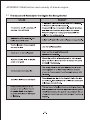
Preface
Safety Information
Engine Specifications
1
Safety Label Location
2
Assembling
2
Engine Usage
3
Start the Engine
6
Electric Wiring Diagram
12
Run the Engine
13
Stop the Engine
14
PeriodicaI Check and Maintenance
15
Long-term Storage
18
Detail Diagram
19
Appendix 1.Overall and lnstallation Dimensions
36
Appendix 2.Performance Curve & Sizes Of Pto Flanges
37
Appendix 3.Sizes of PTO Flanges & Size of Output Shaft
38
Appendix 4.Malfunction and remedy of diesel engine
39
Limited Warranty
43
Product Registration Card
45
!
To correctly operate your engine are for your own safety,be
sure to read this manual carefuIly,otherwise the accident will
result.
If you have problem about your engine,please contact with
sales company or the authorized agent.
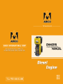
PREFACE:
These manual guides you how to operate air-cooled diesel engine correctly,as well as
the warnings,Be sure to read this manual before operating,to keep your engine at the best
working condition.
This manual should be considered as the permanent part of the engine for easy checking
up.
Should this manual missing or destroyed,please make an order from your agent.If you
have anything unclear about this manuaI,please contact your agent.
air-cooled desel engine wiIl meet your requirement if you operate it according
to the manual instruction. Otherwise the fire,scald etc serious accident will result.
So reconfirm that you must to master this manual before operating the engine.
!
!
!
DANGER
WARNING
CAUTION
Indicates that the serious personal injury even death will resuIt if the instructions are not followed.
Indicates that the serious personaI injury even death will result if the instructions are not followed.
Indicates that the serious personaI injury or equipment damage will
result if the instructions are not followed.
indicates that you must give special attention while operating the engine.Otherwise the engine performance
will decreased even the fault will result.Be sure to follow the
[OPERATING NOTICE]
[OPERATING NOTICE]
S A F E T Y I N F O R M AT I O N
(To operate the engine safely,please follow these items strictly.)
!
DANGER
To prevent the fire,please pay attention to the follwing items:
If the gasoline is filled into the engine,the fire will result,so identify the
fuel type and model before refilling.
Be sure to stop the engine before refilling.
Wipe off the overflowed fuel oil.
Keep the engine far away from other flammable oils and goods.
!
DANGER
Be careful when use the battery:
The battery will exhaust hydrogen while charging.Do charge the battery
at the well ventilated place.Meanwhile,flame and spark are not allowed
while charging.
The electrolyte is heavy acid solution,be sure skin and eyes do not touch
it,otherwise,rings with water immediately.
!
WARNING
The exhaust is poisonous,pay attention to the following:
The exhaust is harmful to the health ,do not run the engine at the confined rooms or unventilated places.If you have to run the engine indoors,
be sure there is good ventilation equipment.
!
WARNING
Be care no to be involved:
Do not touch the moving parts while the engine is running,meanwhile,
when the engine is linked to the load,please cover the coupler and belt
etc parts which have potential danger before running.
!
CAUTION
Be care of the hot parts:
The muffler and the engine body will be very hot during running or just
after running,do not touch these parts.
!
WARNING
Other safety information:
Do not operate the engine after drinking.
Be sure that the surrounding is safe before starting the engine.
Put on the uniform and anti-slippery shoes.
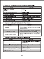
Main Items
AHD170
Type
AHD178
AHD186
Single-cylinder,4-stroke,vertical,air-cooled,
direct-injection diesel engine
Combustion System
Direct injection combustion
Bore x Stroke(mm)
70 x 57
78 x 64
86 x 72
0.219
0.305
0.418
Max.kW(PS)
4.2
6.0
9.0
Continue.kW(PS)
3.8
5.5
8.5
Piston Displacement(L)
Rated Power
Rated Speed(rpm)
Output Shaft
Rotation direction
Fuel Oil
Unclockwise viewed from the output shaft
Spray Pressure kg/cm2(MPa)
200(19.6)
Applicable Fuel Oil
Light diesel
Fuel Tank Capacity(L)
Lubricating
System
2.5
3.5
Lubricating Method
Pressure plus splashing
Applicable Lube Oil
SAE 10W30 beyond CC grade
Lube Oil
Full(L)
Capacity Effective(L)
5.5
0.75
1.1
1.65
0.25
0.4
0.6
Starting System
Recoil starter or Recoil/Electric starter
Cooling System
Forced air-cooled
1
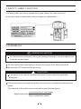
2.SAFETY LABEL LOCATION
This label guides you how to operate the engine safely.If the label comes off
or becomes hard to read,contact with your agent for replacement.
AMICO
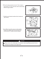
3.ASSEMBLING
[OPERATING NOTICE]
Too much shock during the running will damage the engine and the load,be sure
to set the engine tightly.
1
Fix the engine base seat tightly to prevent the engine from offset and shock.
2
Be sure the PTO shaft centers are in line.
!
CAUTION
If the pulley is too tight,the accident will result.Please select the applicable
size pulley.
3
If the puIley drives the engine,the pulley size must be in conformance with the load
speed.
The diameter of the pulley can be calculate by the following format:
Load side pulley X load speed
Engine side pulley=
Egine speed(rated speed)
2
4
Make sure that the bearing hole of the pulley,keyway size are in conformace with the PTO
shaft.Othewise the accident will result.Correctly tight the PTO shaft bolt.Do reselect the
appropriate diameter pulley,if the engine continually exhaust black smoke during the running.
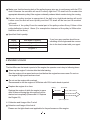
5
Be sure the pulley tension is appropriate.If the belt is too tight,hard starting will result,
further more,the belt will worn quickly and the PTO shaft will be bent,so the accident
will result.
The torsion of the pulley:Press the central part of the pulley surface.Every 100mm of the
pulley,deflection is about 1.6mm.(For example:the clearance of the pulley is 500mm,the
deflection will be 8mm.)
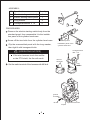
6
Specified V-belt quantity:
Model
Belt Model x Quantity,
AHD170
A type x 2
AHD178
B type x 3
AHD186
B type x 3
If you have any question about the assembling of the engine and the connection to the load,contact with your agent.
4.ENGINE USAGE
The first 20hrs are the break-in period of the engine,the operator must obey to following items:
Warm up the engine 5 minutes after the initial starting.
Run the engine at low speed and zero load before the engine becomes warm.Do not run
the engine at high speed and zero load.
Do not run the engine with overload,
Recommend to run the engine at 3600r/min with 50% load in break-in period.
Replace the engine oil on time.
about 20hr
starting
Replace the engine oil while the engine is warm
after 20-hours-running,the old engine oil will be
drained out completely.(Please see 8.1 Replace
the Engine Oil)
about 20hr
every 100hr in future
replace engine oil
4-1 Selection and Usage of the Fuel oil
1
Selection and Usage of the fuel oil
Please use the light diesel most applicable for the performance of the engine.
3
2
3
Diesel usage:
If diesel is mixed with water and dirty,the abnormal running will result.Seal the diesel in
clean drums and store the drums in a dry place away from the rain and dirty.
If diesel has been stored for several hours,the water and dirty will deposit at the bottom of
the drum.You can pump the upper portion of the diesel for usage.
Refill the diesel
!
DANGER
It is very dangerous to fill the gasoline into the diesel engine.Do identify the fuel oil
type and model before refilling.
do stop the engine before refilling.
Wipe off the overfiowed diesel.
!
DANGER
Water and foreign matter will be sunk into the lower position in the
barrel.Put the suction pipe into the barrel at the place with a half
depth of the barrel,pump clean oil on the upper position in the
barrel.
FUEL OIL CAPACITY
!
Model
Fuel Oil Capacity
AHD170
2.5
AHD178
3.5
AHD186
5.5
CAUTION
Cap
Do not let fuel level be
higher than Red Mark
Red mark
4-2 Selection and Usage of the Engine Oil
1 Selection of the Engine Oil
It is very important to select the appropriate engine oil.If you use the improper diesel,the
piston rings will adhere together,the pistion will burn out,and the cylinder head gasket will
wear out quickly as well as bearings and other moving parts like that , so the engine life will
be shortened.
Recommend CC/CD oil classified by API in four seasons.
The viscosity of the engine oil is depended on the ambient temperature.
Ambient Temperature Above 20 C(summer) 10-20 C(spring,fall) Below10 C(winter)
SAE 30
SAE 20
4
SAE 10W-30
2
Check and Refill the Engine Oil
[OPERATING NOTICE]
Check the engine oil level with the engine on a level surface and the engine stopped.
Check the engine oil level before tightening the filler cap.
A.Be sure to check the engine oil level before starting the engine.
Check whether the engine oil level is between the upper level and the lower level.
wipe off the overflowed engine oil.
Screw on the oil filler cap after checking.
B.The engine oil level can not beyond the upper level.
C.The following is the oil capacity table:
AHD170 AHD178 AHD186
Engine Oil capacity 0.75L
1.10L
1.65L
High Limit(H)
Dipstick
Low Limit(L)
Oil drain screw plug
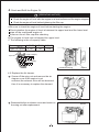
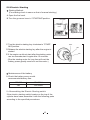
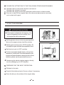
4-3 Replace the Air cleaner
1 Screw off the wing nut and remove the air
cleaner cover.If the engine is not
sufficient,the exhaust color will be abnormal,
then it is necessary to replace the element.
2
Reassemble the air cleaner cover and screw on
the wing nut after replacement.
5
air cleaner cover
Dipstick
Wing nut
element
4-4 The Exhaust Direction
muffler
To prevent the exhaust from flowing into the air
cleaner,assemble an exhaust syphon on the case
of the muffler
!
NOTE
Prevent the water from accumulating on the
exhaust syphon form flowing into the muffler.
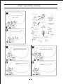
5.START THE ENGINE
fuel tank
5-1 Manual Starting:
1
Start the engine according to the following
procedures:
Open the fuel cock.
fuel cock ("OPEN")
2
Turn the governor lever to "STARTING"position
regulator handle
3
Hold the recoil starter handle
A.
Pull the starter handle until you feel the resistance,
starter
handle
then return the handle slowly.
recoil starter
6
B.Press the decompression lever to "Non-compression"position.The lever will return back automatically
after the engine started.
decompression lever
C.Hold the recoil starter handle with two hands and
pull it hardly.
starter
handle
recoil starter
D.It is difficult to start the engine at cold weather.
Remove the rubber plug on the cylinder head
and fill about 2CC engine oil before starting.
!
NOTE
Always screw on the rubber plug on the cylinder head except filling,to prevent the rain
and dirty from flowing into the engine body.
7
START THE DIESEL ENGINE
1
Start!
Open the fuel cock.
6
2
Put the engine speed lever
in the "RUN" position
If the engine doesn't start
try again from
Pull the rope hard and fast
Pull it all the way out.
Use two hands if necessary.
3
Hold the starting handle
loosely
5
Pull the starting
handle slowly......
Hold the starting
handle firmly.
...... until you feel
resistance
4
Push the decompression
lever down and release
Then return it slowly.
8
START THE DIESEL ENGINE
For3, don't pull the rope
too fast or hard.
Always pull the rope slowly.
For5,if you don't pull hard
enough,the engine won't start
For5,if you don't pull the rope
all the way out ,the engine won't
start
Always pull the rope all the
way out.
Always pull the rope hard
and fast.
9
5-2 Electric Starting
1 Starting Method:
(Pre-starting check is same as that of manual starting.)
A.Open the fuel cock.
B.Turn the governor lever to "STARTING"position.
fuel tank
AMICO
regulator handle
fuel cock("OPEN")
C.Turn the electric starting key clockwise to "STARTING"position.
D.Release the electric starting key after the engine is
started
E.If the engine could not start after the starting motor
ran ten seconds,start it again after 15 seconds.
(Run the starting motor for long time will cost the
battery power greatly even burn out the motor.)
Maintenance of the battery
A.Check the battery every month.
recommended battery size:
2
170/178
186
12V/20AH
12V/24AH
5-4 Assembling the Electric Starting switch
If the electric starting switch locates on the top of the
cylinder head case,assemble it with the following parts
according to the specified procedures:
10
OFF
ON
ST
ASSEMBLY:
NO. Specification
Quantity
1
Electric starting switch body
1
2
Electric starting switch panel
1
3
Long washer
2
4
Hexagonal bolt M6 x 70
2
1
2
3
PROCEDURES:
1 Remove the electric starting switch body from the
standard panel, then reassemble it to the installation panel of the cylinder head case.
2
3
Screw off the two bolts from the cylinder head case.
Clip the reassembled panel with the long washer,
then tight it with hexagonal bolts.
standard panel
installation panel of the
cylinder head case
hexagonal bolt
M6 x 70
[OPERATING NOTICE]
If the wire harness touch the muffler
or the PTO shaft, the fire will result.
remove
two bolts
4
long
washer
Set the earth terminal of the harness with M6 bolt.
ground
terminals
wire harness
M6 bolt
coupler
11
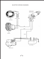
ELECTRIC WIRING DIAGRAM
red
blue
blue
gray
black
blue
white
starting key of
diesel engine
yellow
red
generator
red
blue
regulator
yellow
red
black
accumulator
12V
starting motor
12
6.Run the Engine
!
WARNING
To prevent the exhaust toxication, be sure to run the engine at ventilated place.
To prevent personal injury, avoid hands, personal body and cloths from involving into
the output shaft, pulley and V pulley etc moving parts.
Check the moving parts and the surrounding parts after stop the engine. Be sure that
there is no tool or cloth inside the engine body.
!
CAUTION
The muffler is very hot during running or just after running, do not touch the muffler.
The air cleaner will suck the surrounding airflow during the running. To prevent the
injury, avoid hands, personal body and cloths approach this part.
1
Warm up the engine for 5 minutes.
2
If the engine is very hot, set the governor lever to the expected position.
!
NOTE
Be sure to regulate the engine speed with the governor lever.
!
NOTE
Do not screw off the adjusting bolt and the fuel adjusting bolts, otherwise the abnormal
speed and output will result.
3
If the engine continually exhaust black smoke during running, which indicates that the engine is running with overload, do adjust the engine pulley and
the load pulley.
speed limiter
F.O. limiter
13
PLEASE PAY ATTENTION TO THE FOLLOWING ITEMS WHILE RUNNING:
1
2
3
Whether there is abnormal vibration and sound.
Whether the exhaust is normal.
Whether the engine continually exhausts white smoke or black smoke.
Be sure to shut off the engine when the abnormal phenomenon arouses,
and contact with agent.
7.STOP THE ENGINE
[OPERATING NOTICE]
If the engine is stopped in emergency, the
engine temperature will rise quickly, thus
the engine life will be shortened.
1
Set the governor lever to the low speed position,
then run the engine at zero load five minutes.
2
Set the governor lever to the *STOP*position. Do
not stop the engine with the decompression lever.
3
Set the fuel cock to*OFF*position.
4
Pull the recoil starter handle slowly, until you feel
resistance. (At this point, the decompression just
begins and intake/exhaust valves are both closed,
thus the cylinder can be prevented from rust.)
5
Concerning the electric starting engine, directly
turn the starting key to*OFF*position.
regulator handle
fuel tank
fuel cock("OPEN")
PREPARE FOR THE NEXT OPERATION:
1
Fill diesel to the tank.
2
Check all the bolts and nuts. Screw on them if necessary.
3
Clean the dirty on the surface of the engine body.
14
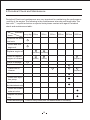
8.Periodical Check and Maintenance
Periodical Check and maintenance are very important for maintaining the performance
and life of the engine.The following is the maintenance intervals and items table.The
item with "." require technician or special tools,please contact with agent.Periodical
check and maintenance table:
Intervals
Items
every day 20hrs
50hrs
100hrs
200hrs
500hrs
1000hrs
Check all the bolts
and nuts
Check and refill
engine oil
Replace engine oil
(First time) (Second time)
Clean or replace
engine oil cleaner
(Clean)
(Clean)
(Replace)
Check oil leakage
Replace air cleaner
Clean fuel oil
cleaner
(Replace)
Check nozzle
Check fuel injection pump
Adjust the clearance of
the intake/exhaust valve
Check the intake/
exhaust valve
Replace the piston
ring
Check the electrolyte
Check it every month,refill the distilled water if necessary.
15
Replace Engine Oil
Drain out the engine oil while the engine is warm
and refill the recommended engine oil.
Oil drain scew plug
Ambient temperature
Above 20 C (Summer)
10 C~20 C (Spring and fall)
Below 10 C (Winter)
Replace Engine Oil
First time
Second time
Dipstick
Grade
Viscosity
Beyond CC grade SAE 30
SAE20
SAE10W-30
Intervals
20 hrs
Every 100 hrs
Clean Engine Oil Cleaner
Screw off the bolt and take out the engine oil
cleaner
Clean
Replace
Every 100 hrs
Every 1000hrs
Screw off the bolt and take
out the engine oil cleaner.
cover
gasket
Oring
oil filter
lock bolt
oil filter
lock bolt
170
O ring
LO suction pipe
178/186
16
1
Replace the air cleaner
air cleaner cover
wing nut
A. Paper element:
Replace the element every 500 hrs.
!
CAUTION
If the element is too dirty, the air flow will be blocked and starting will be hard, thus
insufficient output will result, further more, it will cost both fuel oil and engine oil, the
engine will exhaust black smoke.
Running engine with worn element or without element is not allowed.
B. Oil-soak Type Element
Check the engine oil level before run the engine.
2
Refill the engine oil until the upper level. Replace if it is too dirty. Often clean the element with
kerosene, then soak it in the engine oil and squeeze
out the excess engine oil.
Oil filter
Oil-soak Type
Element
Oil level
4 Clean the Fuel Oil Cleaner
Remove the fuel oil cleaner from the tank and clean
it on time.
Clean
Replace
Every 500 hrs
Every 1000 hrs
Oil drain
screw
plug
A. Completely drain out the fuel oil.
B. Screw off two nuts of the fuel cock and take out
the fuel oil cleaner.
5
Drain plug
fuel cock bolt
Screw on the bolts on the cylinder head. This operation requires special tools, please
contact with your agent.
17
6
The adjustment of fuel nozzle and fuel injection pump and the replacement of the valve
seats, parts require special technology, please contact with your agent.
7
Check the battery every month.
9.LONG-TERM STORAGE
Prepare the following items before long-term
storage:
1
Run the engine five minutes at low speed.
2
Drain out the engine oil while the engine is warm
and refill the fresh engine oil.
3
Remove the filler screw plug on the cylinder head
case and refill about 2cc engine oil.
4
Press down the decompression lever and pull the
recoil starter 2-3 times(Do not start the engine)
5
Return the decompression lever back to the decompression position, and pull the recoil starter
slowly until you feel the resistance.(At this point,
both intake/exhaust valves are closed to prevent
the engine from rust.)
6
Clean off the dirty on the engine surface, then store
the engine at the dry place.
Oil drain screw plug
Dipstick
decompression lever
starter
handle
recoil starter
18
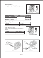
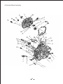
10.DETAIL DIAGRAM
19
20
Ref No.
CAUTION
AIR-COOLED
DIESEL
Do not wash the air cleaner element with detergent
Replacement cycle is every 500 hours
Replace when output decreases or bad exhaust color is
notired
6
7
5
WARNING
Use light diesel fuel No.0 in summer,
Part No.
Description
Qty.
1
186F ~ 18003
Trade Marks Tag I
1
2
186F ~ 18004
Start Operation Tag
1
3
186F ~ 18005
Caution Tag
1
4
186F ~ 18007
Model Tag
1
5
186F ~ 18009
Warning Tag
1
6
186F ~ 18012
Air Cleaner Tag
1
7
186F ~ 18013
Air Cooled Diesel Engine Tag 1
No.-10 or No.-20 in winter.
ES
GRADE CC or CD.
ESE
EL
DI
The engine must be used lube oil
At first 20 hours run the engine at tow
speed and low load
to keep your engine in best
working condition and make it
L
DI
1
run longer.
Torque of Main Bolt & Nut
Please read the operation manual
Unit:N. m
before running the engine.
2
HOW TO START
1 Open the fuel cock.
Ref No. Description
3
2 Put the lever in the
"START" position.
CAUTION
1
Rod Bolt Nut
40~45
2
Cyl Head Nut
54-58
3
Flywheel Nut
120~135
4
Nozzle Retainer Nut
8 ~10
5
Rocker Arm Tighten Stud
20~22
6
Bolt M6 (Nut)
10~12
7
Bolt M8 (Nut)
18~22 I
FUEL OIL
USE DIESEL FUEL
CLEAN FILTER EVERY 300hrs.
LUBE OIL
3 Pull the starting
handle slowly.
SAE IOW30 GRADE / CC.
CHANGE LUBE OIL EVERY 100hrs.
4
Pull until you feel
resistance.Then
return it slowly.
CLEAN FILTER EVERY 100hrs.
STARTING
4
CHECK LUBE OIL LEVEL
5 Push the decompression lever down and release.
AND FUEL.
186 Air Cooled Diesel
FOR EASY STARTING IN COLD
WARM UP WITHOUT LOAD.
Max.Output
6.3kW 6.8kW
Cont.Output
5.7kW 6.3kW
Engine Speed 3000rpm 3600rpm
Displacement 0.406L
Serial No.
STOPPING
CLOSE FUEL COCK.
6
Pull the rope
hard and fast.
AFTER STOPPING ENGINE.
If the engine doesn't start.try again from. 3
Full Gasket Sets
Ref No.
a
b
c
d
e
f
g
h
i
J
k
Torque
Part No.
186F-01100
186F-10017
186F-10016
186F-01015
186F-02014
186F-02015
186F-03003
186F-07001
186F-09002
186F-10007
186F-10013
Rings
Qty.
Description
2
Oil Plug Gasket Assem.
Fuel Injection Pump Shim Set 1
1
Seal Gasket
1
Crank Case Gasket
1
Air Intake Gasket
1
Exhaust Gasket
1
Bonnet Gasket
1
Air Cleaner Gasket
1
Oil Filter Plate Gasket
1
Fuel Oil Filter Gasket
1
Connecting Plate Gasket
Full Gasket Sets
Ref No.
1
Part No.
Description
Qty.
186F-11008
Lever shaft Seal
1
Ref No.
m
n
o
P
q
r
s
t
Part No.
186F-01007
GB3452.1-92
GB3452.1-92
GB3452.1-92
GB3452.1-92
GB3452.1-92
GB3452.1-92
GB3452.1-92
Description
Qty.
O-RingZ
1
O-Ring 11 x 1.9G
1
O-Ring 24 x 2.4G
2
O-Ring 10 x 1.9G
1
O-Ring 25 x 2.4G
1
O-Ring 34.5 x 1.8G 1
O-Ring 13.2 x 1.9G 1
O-Ring 12 x 1.8G
1
Bearings
Ref No.
u
v
w
x
Y
Part No.
GB ! T276-94
GB/T276-94
GB290-89
GB290- 89
GB / T276- 94
Description
Qty.
Ball Bearing 6308/P5
1
Ball Bearing 6207/P5
1
Needle Bearing HK081210 2
Needle Bearing HK1512
1
Ball Bearing 6203
2
Easy Worn Parts
Ref No.
A
B
C
D
E
F
G
H
I
J
K
L
Part(Type) No.
186F-04100
186F-04001
186F-04002
186F-04005
GB9877 ~ 1-88
11.433 ~ 172.001
186F-02007
186F-t0300
186F-07100
186F-0t012
GB9877 ~ 1-88
186F-14008
Description
Oil Ring Set
First Gas Ring
Second Gas Ring
Crank Pin Bearing
Oil Seal B355010D
Nozzle
Spacer
Filter Element Assem.
Air Cleaner Element Assem.
Cyl. Head Gasket
Oil Seal B355008D
Starter Ratchet
21
Qty.
1
1
1
2
1
1
1
1
1
1
1
1
Mounted to
(4)Piston & Connecting Rod Assem.
(4)Piston & Connecting Rod Assem.
(4)Piston & Connecting Rod Assem.
(4)Piston & Connecting Rod Assem.
(1)Cylinder Block Assem.
(13)Fuel Nozzle Assem.
(2)Cylinder Head Assem.
(ll)Fuel Tank & Pipe Assem.
(7)Air Cleaner Assem.
(1)Cylinder Block Assem.
(1)Cylinder Block Assem.
(14)Recoil Starter Assem.
(1)Cylinder Block Assembly
22
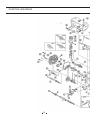
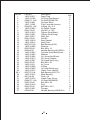
Ref No.
1
2
3
4
5
6
7
8
9
10
11
12
13
14
15
16
17
18
19
20
21
22
23
24
25
26
27
28
28-1
29
30
31
32
33
34
35
36
37
Part No.
186F-01017
186F-01100
GB9877.1-88
186F-01001
186F-11200
GB3452.1-92
186F-01002
GB6173-86
186F-01012
186F-01001
186F-10017
GB6170-86
186F-10016
186F-10015
GB/T276-94
186F-01009
GB5783-86
GB290-89
186F-01003
186F-01005
186F-01004
186F-01013
186F-01007
GB5787-86
186F-01211
186F-01008
186F-01006
186F-01015
GB/T276-94
186F-01014
GB 119-86
186F-01016
GB9877.1-88
GB5787-86
186F-01019
GB5787-86
186F-01021
GB290-89
Description
Drain Plug
Oil Plug Seal Assem.
Oil Seal B355010D
Cylinder Block
Fuel Controller Assem.
O-Ring 24 x 2.4
Oil Depth Gauge
Nut M10 x 1.25
Tighten Stud(Short)
Tighten Stud(Long)
Shim Set
Nut M6
Seal Gasket
Seal Plate
Ball Bearing 6308
Retainer
Bolt M8 x 12
Needle Bearing HK152015
Cylinder Head Bolt(Shortl
Washer
Cyl. Head Nut(Short)
Cyl. Head Gasket
Cyl.Head Nut(Long)
Bolt M6 x 20
Air Cover
O-Ring
Cyl.head Bolt(Long)
Crank Case Gasket
Ball Bearing 6207-P5
Main Bearing
Pin8 x 10
Crank Case Cover
Oil Seal B355008D
Bolt M8 x 30
Plug
Bolt M8 x 33.5
Plunger
Needle Bearing HK081210
23
Qty.
2
2
1
1
1
2
2
1
1
2
2
3
1
1
1
1
1
1
2
4
2
1
2
2
1
1
2
1
1
1
2
1
1
2
1
13
3
1
(2)Cylinder Head Assembly
Ref No.
1
2
3
4
5
6
7
8
9
10
11
12
13
14
15
16
17
18
19
20
21
22
23
24
25
Part No.
186F-02014
186F-02202
186F- 02003
186F-02004
186F-02015
GBl19-86
186F-02007
186F-02019
186F-02005
186F- 02002
186F-02008
GB6177-88
186F-02017
186F-02012
186F-02006
186F-02013
186F-02001
GB6177-88
186F-02009
186F-02018
186F-02011
GB900-88
GB900-88
GB5787-86
GB899-88
Description
Air Intake Gasket
Cylinder Head
Intake Valve
Exhaust Valve
Exhaust Gasket
Pin B4 x 8
Washer
Valve duct Seal
Valve Spring
Valve Spring Retainer
Valve Screw
Nut M6
Rocker Arm Screw
Exhaust Valve Rocker Arm
Rocker Arm Support
Intake Valve Rocker Arm
Cotter
Nut M6
Nozzle Retainer
Spacer Washer
Spacer
StudAM6 x 50
Stud AM6 x 75
Bolt AM6 x 25
Stud AM8 x 20
24
Qty.
1
1
1
1
1
1
2
2
2
2
2
2
1
1
1
1
4
2
1
1
1
2
2
3
2
(3)Cyl. Head Bonnet Assembly
Ref No.
1
2
3
4
5
6
7
8
9
10
11
12
13
186FG
1
2
3
4
5
6
7
8
9
10
Part No.
GB119-86
186F-03001
186F-03006
186F-03007
GB3452.1-92
186F-03003
186F-03014
186F-03015
186F-03004
GB3452.1-92
186F-03100
GB5787-86
186F-03016
Description
Pin B3 x 16
Cyl. Head Bonnet
Ball
Breather Seat
O-Ringl2 x 1.9
Bonnet Gasket
Pin
Plunger8
Decompression Spring
O-Ringl2 x 1.9
Decompression Shaft Assem.
Blot M6 x 70
Oiling Screw Plug
186FG-03012
186FG-03100
186FG- 03011
186FG- 03009
186FG- 03008
GB97.1-85
GB5783-86
186FG-03013
GB3452.1-92
GB6170-86
Decompression Wire Collar
Decompression Shaft Assem
Decompression Wire
Outer Decompression Handle
Decompression Handle Suppor
Washer6
Bolt M6 x 15
Outer Decompression Handle Bushin
O-Ringl2 x 1.9
Nut M6
25
Qty.
l
1
1
1
1
1
1
1
1
1
1
2
1
2
1
1
1
1
2
3
2
1
1
(4)Piston & Connecting Rod Assembly
Ref No.
1
2
3
4
5
6
7
8
9
10
Part No.
186F-04100
186F-04001
186F-04002
186F-04003
186F-04004
GB893.1-86
186F- 04008
186F-04007
186F-04005
186F-04006
Description
Qty.
Oil Ring Set
1
First Gas Ring
1
Second Gas Ring
1
Piston
1
Piston Pin
1
Washer 23
2
Rod Bolt
2
Connecting Rod Body 1
Crank Pin Bearing
2
Crank Pin Box
1
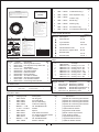
(5)Fuel Nozzle Assembly
Ref No.
Part No.
11.435.127.003
11.430.100.240
1
2
11.430.613.001
11.433.120.000
3
4
11.430.136.000
11.433.261.004
5
6
11.433.172.001
11.433.314.009
7
8
26
Description
Qty.
Nozzle Holder Assem. 1
Shim Pack
1
Nozzle Spring
1
Spring Retainer
1
Stop Plate
2
Pin
Nozzle Valve
1
Nozzle Case Nut
1
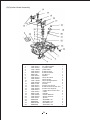
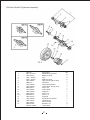
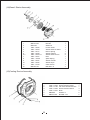
(6)Crank Shaft & Flywheel Assembly
Ref No.
1
2
3
4
5
6
7
8
9
10
11
12
12-1
13
14
15
16
17
Part No.
GB / T276-94
186F-05301
186F - 05006
186F - 05004
186F-05007
GB93-87
186F-05005
186F-05203
GB1096-79
186F-05201
186F-05202
GB1096-79
GB1096-79
186F-05101
186F-05003
186F-05002
186F-05001
GB5787-86
186FG- 05006
Description
Ball Bearing 6203/P5
Balancer Shaft
Key
Balancer Gear
Output End Tighten Stud
Washerl0
Output End Washer
Crank Shaft Timing Gear
Key6 x 50
Crank Shaft
Plunger6
Key5 x 12
Key5 x 14
Flywheel
Flywheel Nut Washer
Flywheel Nut
Starter Pulley
Bolt M6 x 12
Crank Shaft
27
Qty.
2
1
2
2
1
1
1
1
1
1
1
1
1
1
1
1
1
3
1
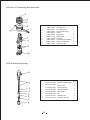
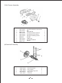
(7)Air Cleaner Assembly
Ref No.
1
2
3
4
5
6
7
8
9
10
Part No.
186F-07300
186F-07301
GB6177-86
186F-07100
186F-07200
186F-07203
GB62-88
186F-07401
186F-07001
GB97.1-85
Description
Air Cleaner Bottom Case Assem.
Bolt
Wing Nut M6
Air Cleaner Element Assem.
Air Cleaner Cover Assem.
Shockproof Sealing Assem.
Nut M8
Intake Pipe
Air Cleaner Gasket
Washer
(8)Camshaft Assembly
Ref No.
1
2
3
4
5
Part No.
186F-0610O
186F- 06003
186F- 06002
GB 1096-79
186F- 06001
Description
Valve Rod Assem.
Valve Tappet
Camshaft Timing Gear
Key 5 x 12
Camshaft
28
Qty.
2
2
1
1
1
Qty.
1
1
3
1
1
2
1
1
1
1
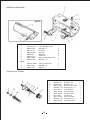
(9)Silencer Assembly
Ref No.
1
2
3
4
5
6
7
8
186FG
1
2
3
Part No.
186F- 08100
GB5787-86
GB97.1-85
GB6170-86
GB859-87
GB97.1-85 186F- 08200
GB5787-86
Description
Case Welded Assem.
Bolt M6 x 8
Gasket 6
Nut M8
Washer8
Gasket 8
-Silencer Welded Assem.
Bolt M6 ~ 12
Qty.
1
6
8
2
2
2
1
2
186FG- 08000
GB5783-86
GB97.1-85
Silencer Assembly
Bolt M8 x 15
Washer 8
1
1
1
(10)Lube Oil System
Ref No.
1
1-1
2
3
4
5
6
7
8
9
10
29
Part No.
GB5787-86
GB5787-86
186F- 09001
GB3452.1-92
186F-09101
186F- 09103
186F- 09102
GB 119-86
186F- 09002
GB3452.1-92
186F- 09200
Description
Qty.
Bolt M6 x 12
3
Bolt H6 x 14
1
Oil Pump Butt Plate 1
O-Ring34.5 x 1.8
1
Inner Rotator
1
Outer Rotator
1
Oil Pump shaft
1
Pin B3 x 16
1
Oil Pump Gear
1
O-Ring25 x 2.4
1
Oil Filter Assem.
1
(11)Fuel Tank Fuel Pipe Assembly
30
Ref No.
1
2
3
4
5
6
7
8
9
10
11
12
13
14
15
16
17
18
19
20
21
22
23
24
186FG
1
2
3
4
5
6
7
8
9
10
11
12
13
14
15
16
17
18
19
20
Part No.
GB5787-86
186F- 10003
186F- 10001
186F- 10002
186F- 10013
186F- 10012
186F- 10005
186F- 10006
186F- 10008
GB5786-86
186F- 10600
GB5787-86
GB6177-86
186F- 10400
GB3452-92
186F- 10011
186F- 10009
186F- 10007
186F- 10300
186F- 10500
186F- 10200
186F- 10004
186F- 10102
186F- 10100
Description
BoltM8 x 50
Bolt
Upper Stay
Damper
Clamp
Fuel Oil Retum Pipe
Clamp
Gauge Pipe
washer
BoltMl2 x 1.25x 14
Lower Stay Assem.
BoltM6 ~ 14
Nut M6
Fuel Tank CockAssem.
O-Ringl3.2 x 1.8
Clamp
Fuel Oil Pipe
Fuel Oil Filter Gasket
Filter Element Assem.
Fuel Injection Pipe Assem
Fuel Tank Welded Assem.
Fuel Oil Filter
Gasket
Fuel Tank Cap Assem.
186FG- 10003
186FG- 10200
186FG- 10004
186FG- 10011
186FG- 10012
186FG- 10607
GB97.1-85
186FG- 10601
GB869-76
186FG- 10602
186FG- 1060:
GB869-76
186FG- 10604
186FG- 10606
186FG- 10605
186FG- 10001
186FG- 10002
186FG- 10100
GB97.1-85
GB5786-86
Adjusting Hole Cover
Fuel Tank Welded Assem.
Fuel Tank Damper
Connecting Plate
Connecting Plate Gasket
Circlip
Washer 2
Floater
Rivet 3 x 5
Swing Bar
Fuel Indicator
Rivet 2.5 x 24
Pointer Support
Sealing Bush
Pointer Window Support
Filter Cup
Filter Cup Supporting Ring
Fuel Tank Cap Assem.
Washer 5
Bolt M5 x 14
31
Qty.
1
1
1
4
2
1
1
1
1
1
1
2
2
1
1
2
1
1
1
!. 1
1
1
1
1
1
1
4
1
1
1
1
1
2
1
1
1
1
1
1
1
1
1
3
3
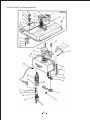
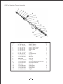
(12)Fuel Injection Pump Assembly
Ref No.
1
2
3
4
5
6
7
8
9
10
Part No.
11.413.372.001
11.414. 628.001
11.410.100.005
11.418.502.108
11.418.600.203
11.413.373.001
11.400 .210.004
11.415.101.001
11.418.205. 501
11.410.050.001
Description
Delivery Holder
Delivery Spring
Delivery Seal Gasket
Delivery Valve Core
Delivery Seat
Joint
O-Ring
F.I. Pump Body
Plunger
Shim Set
11
12
13
14
15
16
17
18
19
GB879-86
11. 415 .700.004
11.410.326.003
11.410.224.001
GB879-86
11.410.506.001
11.414.633.001
11.410.330.003
11. 418.731.001
Pin2 x 6
Packing
0il Control Muff Welded Assem.
Steel Wire Retainer
Pin3 x 8
Spring Seat
Plug Spring
Spring Seat
Tappet
32
Qty.
1
1
1
1
1
1
1
1
1
2
1
1
1
1
2
1
1
1
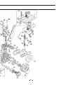
(13)Governor & Control System
33
Rcf No.
1
2
3
4
5
6
7
8
9
10
11
12
13
14
15
16
17
18
19
20
21
186FG
1
2
3
4
5
6
7
8
9
10
11
12
13
Part No.
186F-11311
186F- 11006
186F-11312
186F-11401
186F- 11301
GB5787-86
GB5787-86
GB6172-86
186F- 11403
186F- 11402
186F- 11005
186F- 11007
186F-11100
GBl17-86
186F- 11003
186FG-11008
186F-11102
186F- 11004
186F- 11001
186F- 11002
186F-11101
Descnption
Control Handle
Return Spring 1I
Pull Rod Head
Handle Bracket
Handle
Bolt M6 ~ 14
Bolt M6 x 18
Nut M6
Pull Bolt
High Speed Limit Screw
Return Spring I
Governor Spring
Lever Fork Part
Pin B3 x 22
Washer
Lever Shaft Oil Seal
Lever shaft
Tappet Speed Regulator
Fly Block
Fly Block Pin
Lever Fork
Qty.
1
1
1
1
1
1
1
2
1
1
1
1
1
2
2
1
1
1
2
2
1
186FG- 11303
186FG- 11302
186FG-11012
186FG-11005
186FG- 11307
GB97.1-85
GB5783-86
GB5782-86
GB6173-86
186FG- 11306
186FG- 11305
186FG- 11302
186FG-11301
Handle Shaft
Handle shaft Gasket
Governor Spring
Return Spring
High Speed Limit Screw
Washer6
Bolt M6 x 12
Bolt M6 x 45
Nut M10 x 1.25
Bowl Cap
Spring
Handle Bracket
Handle
1
2
1
1
1
1
1
1
1
1
1
1
1
34
(14)Reeoil Starter Assembly
Ref No.
1
2
3
4
5
6
6-1
7
8
9
10
11
12
Part No.
GB6170-86
GB93-87
186F- 14002
186F- 14004
186F- 14011
186F- 14008
186F- 14001-01
186F- 14001
186F - 14006
186F- 14007
186F- 14005
186F- 14100
GB5787-86
Description
Nut M8
Washer 8
Friction Plate
Starter Ratchet Gland
Return Spring
Starter Katchet
Starter Ratchet Axle
Reel
Spiral Spring
Starter Handle
Starter Rope
Case Assem.
Bolt M6 x 12
Qty.
1
1
1
1
1
2
2
1
1
1
1
1
4
(15)Cooling Device Assembly
Ref No.
1
2
3
4
5
6
35
Part No.
186F- 17003
186F- 17100
186F- 17002
186F- 17001
GB96-85
GB5787-86
Description
Qty.
Shock Absorber Seat
1
Fan Case Welded Assem 1
Shock Absorber Bush
4
Bush
4
Washer 6
5
Bolt M6 x 22
5
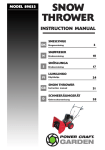
APPENDIX 1.OVERALL AND INSTALLATION DIMENSIONS
AMICO
DIESEL ENGINE
AMICO
DIESEL ENGINE
Air-cooled
DIESEL ENGINE
AMICO
DIESEL ENGINE
Air-cooled
DIESEL ENGINE
36
AHD186
AHD178
AHD170
APPENDIX 2.PERFORMANCE CURVE & SIZES OF PTO FLANGES
37
AHD186
AHD178
AHD170
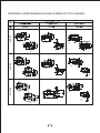
APPENDIX 3.SIZE OF OUTPUT SHAFT
38
APPENDIX 3.Malfunction and remedy of diesel engine
3-1
s
39
3-2
40
3-3
3-4
3-5
41
3-6
3-7
42
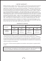
LIMITED WARRANTY
AMICO will repair or replace, free of charge, any part or parts of the generator that are defective
in material or workmanship or both. Transportation charges on parts submitted for repair or
replacement under this Warranty must be borne by purchaser. This warranty is effective for the
time period and subject to the conditions provided for in this policy. For warranty service, find
the nearest Authorized Service Dealer by contacting the place of purchase or AMICO THERE IS
NO OTHER EXPRESSED WARRANTY. IMPLIED WARRANTIES, INCLUDING THOSE OF
MERCHANTABILITY AND FITNESS FOR A PARTICULAR PURPOSE, ARE LIMITED TO ONE
YEAR FROM PURCHASE, OR TO THE EXTENT PERMITED BY LAW ANY AND ALL IMPLIED
WARRANTIES ARE EXCLUDED. LIABILITY FOR CONSEQUENTIAL DAMAGES UNDER ANY
AND ALL WARRANTIES ARE EXCLUDED TO THE EXTENT EXCLUSION IS PERMITTED BY
LAW. Some states do not allow limitations on how long an implied warranty lasts, and some
states do not allow the exclusion or limitation of incidental or consequential damages, so the
above limitation and exclusion may not apply to you. This warranty gives you specific legal rights
and you may also have other rights, which vary from state to state.
WARRANTY PERIOD
WITHIN U.S.A AND CANADA
ENGINES
DIESEL
ENGINE
OUTSIDE U.S.A. AND CANADA
CONSUMER
USE
COMMERCIAL
USE
CONSUMER
USE
COMMERCIAL
USE
1 year or
1000 hours
1 year or
1000 hours
1 year or
1000 hours
1 year or
1000 hours
The warranty period begins on the date of the purchase by the first retail consumer or
commercial end user, and continues for the period of time stated in table above. "Consumer
use" means personal residential household use by a retail consumer. "Commercial use" means
all other uses, including use for commercial, income producing or rental purposes. Once the
engine has experienced commercial use, it shall thereafter be considered as a commercial use
engine for purposes of this warranty.
A two-year or 1500 hour warranty applies to the emission control system on engines certified
by EPA
IMPORTAT"WARRANT REGISTRATION IS NECESSARY TO OBTAIN LIMITED WARRANTY
ON OUR ENGINES.THE WARRANTY REGISTRARION CARD MUST BE RETURNED WITHIN
15 DAYS OF ORIGINAL PURCHASE FOR LIMITED WARRANTY TO BE VALID."
43
About Your Product Warranty
AMICO welcomes warranty repair and apologizes to you for being inconvenienced. Any
Authorized Service Dealer may perform warranty repairs. Most warranty repairs are handled
routinely, but sometimes warranty service may be inappropriate. For example, warranty
would not apply if an engine is damaged because of misuse, lack of routine maintenance,
shipping, handling, warehousing and improper installation. Similarly, warranty is void if the
serial number on the engine has been removed or if the engine has been altered or
modified. If a customer differs with the decision of the Service Dealer, an investigation will
be made to determine whether the warranty applies. Ask the Service Dealer to submit all
supporting facts to his Distributor or the factory for review. If the distributor or the factory
decides that the claim is justified, the customer will be fully reimbursed for those items that
are defective. To avoid misunderstanding, which might occur between the customer and the
dealer, listed below are some of the causes of engine failure that the warranty does not
cover.
Normal wear:
Engines and generators, like all mechanical devices, need periodic parts service and replacement
to perform well. Warranty will not cover repair when normal use has exhausted the life of a part
of an engine.
Improper maintenance:
The life of an engine or your equipment depends upon the conditions under which it operates,
and the care it receives. Some applications, such as tillers, pumps, and rotary movers, are very
often used in dusty or dirty conditions, which can cause what appears to be premature, wear.
Such wear, when caused by dirt, dust, spark pug cleaning grit, or other abrasive material that
has entered the engine because of improper maintenance is is not covered by warranty.
This warrant covers engine related defective material and/or workmanship only, and not
replacement or refund of the equipment to which the engine may be mounted. Nor does
the warranty extend to repairs required because of:
1.ROBLEMS CAUSED BY PARTS THAT ARE NOT ORIGINAL OUR PARTS.
2.Equipment controls or installations that prevent starting, cause unsatisfactory. engine
performance manufacturer.
3.Leaking carburetors, clogged fuel pipes, sticking valves, or other damage, caused by using
contaminated or stale fuel. (Use clean, fresh*lead-free gasoline.)
4.Parts which are scored or broken because an engine was operated with insufficient or
contaminated lubricating oil, or an incorrect grated of lubricating oil (check oil level daily or
after every 8 hours of operation. Refill when necessary and change at recommended
intervals.) Engine damage may occur if oil level is not properly maintained. Read Operation
& Maintenance Instructions.
5.Repair or adjustment of associated parts or assemblies such as clutches, transmissions,
remote controls, ect., which are not manufactured by US
6.Damage or wear to parts caused by dirt, witch entered the engine because of improper air
cleaner maintenance, re-assembly, or use of a non-original air cleaner element or cartridge.
Read Operating &Maintenance Instructions.
7.Parts damaged by over-speeding, or overheating caused by grass, debris, or dirt, which plugs
or clogs the cooling fins, or flywheel area, or damage caused by operating the engine in a
confined area without sufficient ventilation.
44
8.Engine or equipment parts broken by excessive vibration caused by a loose cutter blades
unbalanced blades or loose or unbalanced impellers, improper attachment of equipment to
engine crankshaft, over-speeding or other abuse in operation.
9.A bent or broken crankshaft, caused by striking a solid object with the cutter blade of a rotary
lawn mower, or excessive v-belt tightness.
10.Routine tune-up or adjustment of the engine.
11.Engine or engine component failure, i.e., combustion chamber, valves, valve seats, valve
guides, or burned starter motor winding, caused by the use of alternate fuels such as, liquefied
petroleum, natural gas, altered gasoline's, ect.
Warranty is available only through service dealers, which have been authorized by our
company .Contact place of purchase or our company for Service Dealer near you.
45
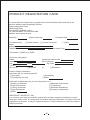
PRODUCT REGISTRATION CARD
For more efficient customer service, please fill out the information below and mail to our
produce Warranty and Registration Division:
Amico International Corp.
4825 Gregg Road,
Pico Rivera, CA 90660, U.S.A
Tel: 562-908-0088 Fax: 562-908-1899
Website: www.amicousa.com
Model No.
Purchase Date.
Engine Serial No.
[ ] Retail location
Purchased from:
Name
Address
Telephone w/area code
[ ] Private Consumer
/
/
[ ] Other
Purchase Price
Purchased: [ ] NEW or [ ] USED
Consumer information :
Name
Address
City
State
Country
Are you a:
[ ] Business
Product Usage Information :
How often will you use this product?
[ ] Everyday
[ ] Emergency use only
Telephone w/area code
Suite or Apt No.
Zip Code
or
[ ] Residence
[ ] Periodically
[ ]Other
What type of application will you use this produce in ?
[ ]Heavy Commercial
[ ]Moderate Commercial
[ ]Light Commercial
[ ] Tradeshows
[ ] Heavy residential
[ ] Moderate Residential
[ ]Light Residential
[ ]Camping, backpacking
[ ]Other
IMPORTANT I NFORIJAT I ON
It is critical to your warranty that the original point of sales receipt be retained by current
consumer, and in order to comply with our product Warranty Statement you must return this
registration card within 15 days of original purchase. Product warranty is valid from original
date of purchase.
46
List for comments from users
Date of Manufacture
Model Number
Name of user
Occupation
Address of user
Place of purchase
Packaging conditions
Operating conditions
Parts Conditions
Malfunction problem
Opinions or suggestions
Note: Please mail the above card to:
Amico International Corp.
4825 Gregg Road,
Pico Rivera, CA 90660, U.S.A
Tel: 562-908-0088 Fax: 562-908-1899
Website: www.amicousa.com