1
Page 6 of 12
SC-1002/1012-10 Installation Instructions
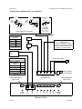
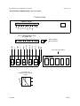
ELECTRICAL CONNECTIONS (ALL MODELS)
+VDC
HORN
RING
SWITCH
+VDC
HORN
RING
SWITCH
SPLICE
Added
SPDT
Switch
MOMENTARY
FOOT
SWITCH
HORN
AUX
HORN
-VDC
switching
example
AUX
AUX
Must set AUX_P
option switch
+VDC Switching examples
Load 1 and Load 2
Recommended
Wire Size
Amps
Size
5 - 10
#16
10 - 15
#14
15 - 20
#12
#22 AWG
WHT
Load
1
#22 AWG ORG
Unit Enable
(like an ON/OFF switch)
Connect to positive circuit
(fuse panel) controlled by
ignition or other switch
Load
2
Use next larger size if
longer than 10 ft.
+
RED
BAT
-
BLK
(2) #18 AWG BRN
RED and BLK (Supply)
Recommended Wire Size
Load 1 + Load 2 +
8 for Amplifier
Size
Amps
8 - 10
#16
10 - 15
#14
15 - 25
#12
25 - 28
#10
Plug installed
this orientation
Use next larger size if
longer than 10 ft.
SPK
SPK
AUX
ENA
LT1
NEG
POS
LITE
FUSE
LT2
6-P Terminal Block Plug
(CP4956-06)
25A Automotive
Type Fuse
15A Automotive
Type Fuse
SIREN
FUSE
Back of Unit
3/27/07
CP4997A