1
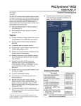
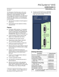
PACSystems* RX3i Power Sync and Measurement System IC694PSM001-AA and IC694ACC200-AA GFK-2748 December 2012 RUN FLT GRID 1 2 PSM001 The PACSystems* Power Sync and Measurement (PSM) system monitors two independent three-phase power grids. It incorporates advanced digital signal processor (DSP) technology to continuously process three voltage inputs and four current inputs for each grid. Measurements include RMS voltages, RMS currents, RMS power, frequency, and phase relationship between the phase voltages of both grids. The PSM module performs calculations on each captured waveform, with the DSP processing the data in less than two-thirds of a power line cycle. The PSM module can be used with wye or delta type three-phase power systems or with single-phase power systems. Module Offset: Module Gain: -2 4000H The PSM system can be used for applications such as: Electrical power consumption monitoring and reporting Fault monitoring Generator control features for generator to power grid synchronization Demand penalty cost reduction/load shedding CAL -2 4000H GRID 1 The PSM system consists of: PSM module – A standard IC694 module that mounts in an RX3i rack. The PSM module provides the DSP capability. Terminal Assembly – A panel-mounted unit that provides the interface between the PSM module and the input transformers. Interface cables – Provide the GRID 1 and GRID 2 connections between the PSM module and the Terminal Assembly. PSM System Features Module Offset: Module Gain: CAL GRID 2 Uses standard, user-supplied current transformers (CTs) and phase voltages (up to 690 VAC), or potential transformers (PTs) as its input devices. Accurately measures RMS voltage and current, power, power factor, frequency, energy, and total three-phase 15-minute power demand. Provides two isolated relays that close when the voltage phase relationships between the two monitored grids are within the specified ANSI 25 limits provided by the RX3i host controller. These contacts can be used for general-purpose, lamp duty or pilot duty loads. Voltage and current ratings for these load types are provided in the PACSystems RX3i Power Sync and Measurement System User’s Manual, GFK-2749. Provides a cable monitoring function that indicates when the cables linking the PSM module and Terminal Assembly are correctly installed. PSM module and Terminal Assembly are easily calibrated by hardware configuration using the Proficy* Machine Edition (PME) software. Ordering Information * IC694PSK001 PSM System. Includes a PSM module, a Terminal Assembly and two interface cables IC694PSM001 Replacement PSM module IC694ACC200 Replacement Terminal Assembly IC694CBL200 One replacement 2m (6.56 ft.) interface cable IC694ACC201 PSM replacement parts: two finger guards four thumb screws one relay connector two grounding lug nuts indicates a trademark of GE Intelligent Platforms, Inc. and/or its affiliates. All other trademarks are the property of their respective owners. All rights reserved. 2 RX3i Power Sync and Measurement System GFK-2748 Specifications PSM Module Power Requirements Backplane Power Consumption 400 mA max. at 5 VDC Total Power Dissipation 2.0 W max. Isolation from Backplane 1500 VDC Maximum number of PSM modules per RX3i system No restrictions, as long as the power supply has sufficient capacity Sync Relay contacts Two isolated relay outputs General purpose: 125 VAC / 125 VDC maximum at 1 amp Lamp duty: 125 VAC / 125 VDC maximum at 1 amp Pilot duty: 125 VAC / 125 VDC maximum at 0.35 amp Measurement Specifications Three voltage inputs per grid All voltage data is scaled in 0.1 VAC units. Impedance: >1 MΩ Range Low range High range 45–150 VAC RMS (120VAC nominal) 120–690 VAC RMS (600VAC CAT IV; 690 VAC CAT III) Frequency 30–70 Hz Four current inputs per grid All current data is scaled in 0.001 Amp units. Impedance <5 milliohms Range 0–5 A RMS (5 A nominal) Frequency 30–70 Hz Phase difference between grids: ±180O Measurement Accuracy 1 Voltage 0.2% Current 0.2% kW, kVAR, kVA 0.4% kWH, kVARH, kVAH 0.4% Power factor 1% Frequency 0.01 Hz Phase angle 0.1O Terminal Assembly Input Terminal Ratings Current 15 Amps continuous maximum Voltage 690 VAC RMS Sync Relay contacts 150 VAC/VDC at 1 Amp Resistive, maximum Note: Actual contact ratings depend on load type. See “Sync Relay contacts” on page 2. RX3i CPU Memory Requirement for Automatic Data Exchange 1 %I 80 bits %Q 32 bits %AI 64 words %AQ 2 words In the presence of severe conducted RF interference (IEC 61000-4-6, 10 volts) accuracy could be degraded by ±2% of full scale. RX3i Power Sync and Measurement System 3 GFK-2748 Data Exchange Time Between RX3i CPU and PSM A complete data exchange between the PSM and RX3i occurs during each controller scan. Minimum scan time is 3.5ms per PSM module in the backplane. Minimum data update rate is one power line period. See “Error! Reference source not found.” and “PSM Status Flags” in GFK-2749 Calculations ANSI 25 – Generator and Public Grid Synchronization ANSI 27 – Under-voltage Protection ANSI 32 – Reverse Power Protection ANSI 46 – Negative Sequence Protection ANSI 50 – Instantaneous Over-current Protection ANSI 59 – Over-voltage Protection ANSI 60 – Voltage (Current) Imbalance Protection ANSI 81U – Under-frequency Protection ANSI 81O – Over-frequency Protection Power Measurement Configurations Four-wire three phase wye systems: 3 PTs and 3 CTs plus Neutral CT (optional) Three-wire three phase delta systems: 2 PTs and 2 CTs Three independent single phase systems: 1 PT and 1 CT for each phase Three-wire single phase systems: 120/240 (2 PTs and 2 CTs) Operating Environment Enclosure mounting Required. PSM module and Terminal Assembly must be installed in a NEMA/UL Type 1 enclosure or an IP20 rating providing at least a pollution degree 2 environment. When this system is installed in an area designated as Class 1 Zone 2 in Europe, compliance with the ATEX Directive requires an enclosure with a minimum rating of IP54. For product standards, general operating sepcifications, and installation requirements, refer to the PACSystems RX3i Power Sync and Measurement System User’s Manual, GFK-2749. Installation in Hazardous Areas WARNING - EXPLOSION HAZARD - SUBSTITUTION OF COMPONENTS MAY IMPAIR SUITABILITY FOR CLASS I, DIVISION 2 or Zone 2; WARNING - EXPLOSION HAZARD - DO NOT DISCONNECT EQUIPMENT UNLESS POWER HAS BEEN SWITCHED OFF OR THE AREA IS KNOWN TO BE NONHAZARDOUS. This equipment is suitable for use in Class I, Division 2, Groups A, B, C and D, Zone 2, or non-hazardous locations only. 4 RX3i Power Sync and Measurement System GFK-2748 Quick Reference Guide Warning HIGH VOLTAGE; HIGH CURRENT DO NOT TOUCH the connectors or wiring after powering up the PSM system. Hazardous voltages exist, and death or injury may result. The Terminal Assembly frame ground connection must always be installed and must be installed before any other wiring is attached. To reduce risk of electric shock or damage to the attached CTs, always open or disconnect all voltage circuits and apply the shorting bar connections to the current inputs before installing or servicing the connections to the Terminal Assembly. Never disconnect the GRID 1 or GRID 2 field wiring while power is present. Personal injury or equipment damage may result. Finger guards must be installed on the Terminal Assembly before energizing the field wiring. Do not hot-swap the PSM module. (Power to the host controller must be off before inserting or removing the module). User-Supplied Equipment The user must supply the following components depending upon the application. This equipment includes: 5 Amp current transformers Potential transformers for all installations 1 Amp fuses for each of the voltage leads connected to the Terminal Assembly. 1 Amp fuse for the common or return line for the voltage lead on the Terminal Assembly. A CT shorting block for each current transformer (CT) connection used on the Terminal Assembly when used with external CTs. Installation The Terminal Assembly and PSM module are considered open equipment (having live electrical parts that may be accessible to users) and must be installed in a protective enclosure or incorporated into other assemblies manufactured to provide safety. As a minimum, the enclosure or assemblies shall provide a degree of protection against solid objects up to 12mm (e.g. fingers). For Non Hazardous environments, this equates to a NEMA/UL Type 1 enclosure or an IP20 rating providing at least a pollution degree 2 environment. When this system is installed in an area designated as Class 1 Zone 2 in Europe, compliance with the ATEX Directive requires an enclosure with a minimum rating of IP54. The enclosure must be able to adequately dissipate the heat generated by all components mounted inside so that no components overheat. Heat dissipation is also a factor in determining the need for enclosure cooling options such as fans and air conditioning. The Terminal Assembly must be securely installed on a rigid, conductive, 12 – 14 gauge steel panel using four user supplied M4 - M5 or #8 - #10 SAE bolts. The Terminal Assembly should be mounted near the host controller rack containing the PSM module, close enough to accommodate the 2 meter interface cables provided. For detailed installation and power system connection instructions, refer to the PACSystems RX3i Power Sync and Measurement Module User's Manual, GFK-2749. RX3i Power Sync and Measurement System 5 GFK-2748 Configuration The PSM module is configured using the Proficy Machine Edition programming software, version 7.50 or later. Configuration parameters are used to set nominal values for Grid1 and Grid2 voltage, current and frequency, and to calibrate the PSM system for specific Potential Transformer and Current Transformer gains, increasing the accuracy of the measured values. Configuration parameters are also used to set ANSI device threshold and delay values. A Mode Control register, consisting of 32 bits in %Q memory, selects operational and measurement modes. This application must apply initial values to these bits and can change them while the PSM is running. The application can change a single configuration parameter in run mode by modifying the two-word Parameter Write register in %AQ memory. Mode Control Bits The RX3i CPU sends 32 %Q bits of Mode Control data to the PSM module every sweep. The application logic must apply initial values to these bits on the first RX3i scan. The application can change these settings during operation to modify measurement modes in response to changing conditions. %Q Bit Offset Function 1 GRID 1 Operation: 0 = disabled, 1 = enabled If disabled, the PSM system does no measurements for the GRID 1 power grid. Note: Both grids (bits Q1 and Q17) must be enabled in order for the PSM module to act as a grid synchronizer. 2 GRID 1 Voltage Selection: 0 = low voltage range (120VAC), 1 = high voltage range (600VAC) Caution: The voltage range is determined by the physical connections in the system. Changing this bit to a value that does not match the physical configuration will result in erroneous power system measurements. Do not change this value in run mode. 3 GRID 1 Grid Operational Mode: 0 = single phase, 1 = three-phase 4 GRID 1 Connection mode. Works with the Operational Mode setting to determine system type. • For single phase mode: 0 = Three single phases 1 = Three-wire, single phase (120/240) using PTA and PTB • For three-phase mode: 0 = WYE, 1 = DELTA 5 GRID 1 PTA_CA measurement: 0 = not measured, 1 = measured Refer to “Reconstructed Variables in the PACSystems RX3i Power Sync and Measurement System User's Manual, GFK-2749.” 6 GRID 1 CTA measurement: 0 = not measured, 1 = measured Refer to “Reconstructed Variables” in GFK-2749. 7 GRID 1 PTB measurement: 0 = not measured, 1 = measured Refer to “Reconstructed Variables” in GFK-2749. 8 GRID 1 CTB measurement: 0 = not measured, 1 = measured Refer to “Reconstructed Variables in GFK-2749.” 9 GRID 1 PTC measurement: 0 = not measured, 1 = measured Refer to “Reconstructed Variables” in GFK-2749. 10 GRID 1 CTC measurement: 0 = not measured, 1 = measured Refer to “Reconstructed Variables” in GFK-2749. 11 GRID 1 CTN measurement: 0 = not measured, 1 = measured Refer to “Reconstructed Variables” in GFK-2749. 12 GRID 1 Waveform Capture: changing from 0 to 1 When the PSM detects a change of this bit from a zero to one, it captures all 128 samples of all seven variables belonging to the grid. 6 RX3i Power Sync and Measurement System GFK-2748 %Q Bit Offset Function 13 GRID 1 Delta Mode: 0 = otherwise B phase is common, 1= with C phase common This bit must be set to 0 if the phase B is used as the common connection for the other two voltages (North American standard). If the phase C is used as the common in a Delta connection, this bit must be set to 1. 14 Reserved 15 GRID 1 Energy reset: When set, the accumulated energy for Grid 1 is reset and held at 0 Wh. When cleared, the Grid 1 energy value represents the accumulated energy in Watt-Hours since power-up, or the last reset. 16 Relay open: Works with bit 32 to control the Sync Relay operation. For more information, see “Relay Open/Relay Close Operation” in GFK-2749. 17 GRID 2 Operation: 0 = disabled, 1 = enabled If disabled, the PSM system does no measurements for the GRID 2 power grid. Note: Both grids (bits Q1 and Q17) must be enabled in order for the PSM module to act as a grid synchronizer. 18 GRID 2 Voltage selection: 0 = low voltage range (120VAC), 1 = high voltage range (600VAC) Caution: The voltage range is determined by the physical connections in the system. Changing this bit to a value that does not match the physical configuration will result in erroneous power system measurements. 19 GRID 2 Grid Operational mode: 0 = single phase, 1 = three-phase 20 GRID 2 Connection mode: Works with the Operational mode setting to determine system type. • For single phase mode: 0 = 3 single phases , 1 = 3-wire single phase using PTA and PTB • For 3-phase mode: 0 = WYE, 1 = DELTA 21 GRID 2 PTA_CA measurement: 0 = not measured, 1 = measured Refer to “Reconstructed Variables” in GFK-2749. 22 GRID 2 CTA measurement: 0 = not measured, 1 = measured Refer to “Reconstructed Variables” in GFK-2749. 23 GRID 2 PTB measurement: 0 = not measured, 1 = measured Refer to “Reconstructed Variables” in GFK-2749. 24 GRID 2 CTB measurement: 0 = not measured, 1 = measured Refer to “Reconstructed Variables” in GFK-2749. 25 GRID 2 PTC measurement: 0 = not measured, 1 = measured Refer to “Reconstructed Variables” in GFK-2749. 26 GRID 2 CTC measurement: 0 = not measured, 1 = measured Refer to “Reconstructed Variables” in GFK-2749. 27 GRID 2 CTN measurement: 0 = not measured, 1 = measured Refer to “Reconstructed Variables” ” in GFK-2749. 28 GRID 2 1 Waveform Capture: changing from 0 to 1 When the PSM detects a change of this bit from a zero to one, it captures all 128 samples of all seven variables belonging to the grid. 29 GRID 2 Delta Mode: 0 = B phase is common, 1=C phase common This bit must be set to 0 if the phase B is used as the common connection for the other two voltages (North American standard). If the phase C is used in a Delta connection, this bit must be set to 1. 30 Reserved 31 GRID 2 Energy reset: When set, the accumulated energy for Grid 2 is reset and held at 0 Wh. When cleared, the Grid 2 energy value represents the accumulated energy in Watt-Hours since power-up, or the last reset. 32 Relay close: Works with bit 16 to control the Sync Relay operation. For more information, see “Relay Open/Relay Close Operation” in GFK-2749. RX3i Power Sync and Measurement System 7 GFK-2748 PSM Status Flags The PSM returns 80 status flag bits to the RX3i controller. Those 80 bits are grouped into five 16-bit words. The first status word (%I1 – %I16) contains the overall PSM status flags. The following two words (%I17 – %I48) contain the individual grid measurement faults. These flags identify the voltage/current channel experiencing a measurement problem. It can be one or multiple problems related to: - Input signal not present, that is, it is indicated as not measured in the corresponding %Q flag bit. If the signal is not measured, it cannot be reconstructed by the PSM module firmware. - Input signal is measured but it is clamped due to a higher peak voltage/current value than the maximum value allowed to be applied to the interface unit The last two status words (%I49 – %I80) contain the individual grid status flags, including the ANSI alarms. %I Bit Offset Value 1 PSM HeartBeatBit: Toggled with every scan/sweep 2 PSM ConnectionOK: 1 = OK, 0 = PSM to Terminal Assembly connection failure 3 PSM PhaseShiftOK: 4 PSM DeltaVoltOK: 5 PSM DeltaFreqOK: 6 PSM ANSIFunctions: 7 PSM CloseRelayOK: 8 PSM New Data: set when the current PLC sweep is the first sweep this power line cycle data is being delivered by the PSM to the PLC 9 - 16 1 = OK, 0 = ANSI 25/1 Alarm 1 = OK, 0 = ANSI 25/2 Alarm 1 = OK, 0 = ANSI 25/3 Alarm 0 = OK, 1 = Any Grid, any ANSI Alarm present 1 = OK, 0 = Do not close relay Reserved 17 GRID 1 FaultVA: 0 = OK, 1 = Fault - not calculated/measured or clamped 18 GRID 1 FaultIA: 19 GRID 1 FaultVB: 20 GRID 1 FaultIB: 21 GRID 1 FaultVA/VBA; VB/VAC; VC/VBC: 22 GRID 1 FaultIC: 23 GRID 1 FaultIN: 24-32 Reserved 33 GRID 2 FaultVA_VCA: 0 = OK, 1 = Fault - not calculated/measured or clamped 34 GRID 2 FaultIA: 35 GRID 2 FaultVB_VCB: 36 GRID 2 FaultIB: 37 GRID 2 FaultVC: 38 GRID 2 FaultIC: 39 GRID 2 FaultIN: 40 - 48 Reserved 49 GRID 1 ClampedFreq: 0 = OK, 1 = Line Frequency outside the range (40 - 70 Hz) 50 GRID 1 ClampedInput: 0 = OK, 1 = some inputs have signal clamped 51 GRID 1 MixedPolarity: 0 = OK, 1 = At least one phase PT/CT has wrong polarity 52 GRID 1 NegSeqAlarm: 0 = OK, 1 = ANSI 46 Alarm 53 GRID 1 UnderVoltAlarm: 0 = OK, 1 = ANSI 27 Alarm 54 GRID 1 ReversPwrAlarm: 55 GRID 1 OverCurrAlarm: 0 = OK, 1 = ANSI 50 Alarm 56 GRID 1 OverVoltAlarm: 0 = OK, 1 = ANSI 59 Alarm 0 = OK, 1 = ANSI 32 Alarm 8 RX3i Power Sync and Measurement System GFK-2748 %I Bit Offset Value 57 GRID 1 VIImbalanceAlarm: 0 = OK, 1 = ANSI 60 Alarm 58 GRID 1 UnderFreqAlarm: 0 = OK, 1 = ANSI 81U Alarm 59 GRID 1 OverFreqAlarm: 0 = OK, 1 = ANSI 81O Alarm 60 - 64 Reserved 65 GRID 2 ClampedFreq: 0 = OK, 1 = Line Frequency outside the range (40 - 70 Hz) 66 GRID 2 ClampedInput: 0 = OK, 1 = some inputs have signal clamped 67 GRID 2 MixedPolarity: 0 = OK, 1 = At least one phase PT/CT has wrong polarity 68 GRID 2 NegSeqAlarm: 0 = OK, 1 = ANSI 46 Alarm 69 GRID 2 UnderVoltAlarm: 0 = OK, 1 = ANSI 27 Alarm 70 GRID 2 ReversPwrAlarm: 0 = OK, 1 = ANSI 32 Alarm 71 GRID 2 OverCurrAlarm: 0 = OK, 1 = ANSI 50 Alarm 72 GRID 2 OverVoltAlarm: 0 = OK, 1 = ANSI 59 Alarm 73 GRID 2 VIImbalanceAlarm: 0 = OK, 1 = ANSI 60 Alarm 74 GRID 2 UnderFreqAlarm: 0 = OK, 1 = ANSI 81U Alarm 75 GRID 2 OverFreqAlarm: 0 = OK, 1 = ANSI 81O Alarm 76 – 80 Reserved LEDs LED RUN FLT GRID 1 GRID 2 State Definition Green The module is operating correctly and communicating with the RX3i. Red The module is operating without backplane communication. Off The module is not operating. Green, blinking During the period when GREEN is ON, Grid 1 can be connected to Grid 2. Green, steady Grid 1 and Grid 2 are connected. Red The module has detected a fault condition. Off The module has not detected a fault and the grids are not synchronized. Green Indicates a voltage signal has been detected on Grid 1. Red A frequency out-of-range condition has been detected on Grid 1. Off No zero crossing signal of Grid 1 has been detected during the last 250 ms time period. Green Indicates a voltage signal has been detected on Grid 2 Red A frequency out-of-range condition has been detected on Grid 2. Off No zero crossing signal of Grid 2 has been detected during the last 250 ms time period. RX3i Power Sync and Measurement System 9 GFK-2748 Field Wiring Wiring to the PSM consists of the connection cable between the Terminal Assembly and the PSM the leads to user-supplied potential and mandatory user-supplied current transformers Sync relay output connections, and frame ground connections from the Terminal Assembly to the chassis. No CT shorting bars are provided on the PSM Terminal Assembly; these must be supplied by the user. Requirements for Terminal Assembly Connections Terminal Assembly connections above 600VAC require prepared wire ends, such as tinning of the conductors, or use of crimpled or soldered forked connectors or ferrules. Terminal connections for COM1, COM2, voltage sensing and current sensing terminals Terminal torque: 1.81 Nm (16 in-lb) Wiring size/type: 0.823 mm2– 5.26 mm2 (18–10 AWG) solid/stranded Relay output terminal connections Terminal torque: 0.8 Nm (7 in-lb) Wiring size/type: 0.205 mm2– 0.410 mm2 (24–21 AWG) solid/stranded For additional wiring and connectin information, refer to the PACSystems RX3i Power Sync and Measurement Module User's Manual, GFK-2749. Warning The PSM Terminal Assembly connects to hazardous voltages. Before installing, testing, or troubleshooting this module, you should refer to the complete instructions in the PACSystems RX3i Power Sync and Measurement Module User's Manual, GFK-2749. Failure to follow the published guidelines may result in personal injury, equipment damage, or both. Note: Although Grid 1 and Grid 2 are interchangeable, you should connect the most stable source to Grid 1. Between a utility grid and a generator, the utility grid is the best choice for connection to the PSM Grid 1 inputs. This will yield the most accuracy and the least reading-to-reading fluctuation. Basic PSM System Connections Grid 1 power system connections to user PTs with fuses and CTs with shorting bars Sync Contacts Load(s) Interface cables Grid 2 power system connections to user PTs with fuses and CTs with shorting bars 10 RX3i Power Sync and Measurement System GFK-2748 Release History Version Firmware Revision IC694PSM001-AA 1.00 Date December 2012 Comments Initial release. Important Product Information for this Release This is the initial release of the RX3i Power Sync and Measurement system. Functional Compatibility Subject Programmer Version Requirements CPU Firmware Version Version Required Proficy* Machine Edition Logic Developer 7.50 with SIM 2 or newer or Proficy Machine Edition Logic Developer 7.00 with SIM 13 or newer or Proficy Machine Edition Logic Developer 7.60 or newer RX3i CPU firmware versions 7.15, 7.16, 7.17, and 7.18. Note: The PSM module is not compatible with IC695CPE305/IC695CPE310 firmware version 7.30. Operational Notes Subject Description Wiring COM1 and COM2 of the IC694ACC200 must be connected to functional ground (Earth ground). COM1 and COM2 must not be connected to Neutral in a WYE power system. In certain fault conditions, Neutral can be pulled to the full voltage of any phase. Such a fault condition can pose a danger to personnel and damage the IC694ACC200. See GFK-2749 for wiring diagrams. Breaker Delay When the ANSI 25 Breaker Delay parameter is set to a non-zero value, the phase angle difference at which RelayCloseOK (%I offset 7) is set and the IC694ACC200 relay outputs close varies in direct proportion to the rate of change of the phase angle of Grid 2 relative to Grid 1. Higher rates of phase angle change and larger breaker delays require that the PSM assert RelayCloseOK earlier, to ensure that the breaker contacts close within the safe region set by the ANSI 25 Phase Shift Threshold parameter Delta Power Configurations Phase-to-Neutral voltages are not reported in Delta power configurations because there is no Neutral reference. Nominal Voltage Nominal Voltage refers to the: Phase-to-Neutral RMS voltage in a WYE power system. Phase-to-Phase RMS voltage in a Delta power system. Nominal Current Setting a negative Nominal Current value implies that the IC694ACC200 grid inputs are connected to a load (drawing power), rather than a power source (producing power). The power and energy values will be reported as negative numbers. The CTs must be wired with the correct polarity to achieve the negative power and energy values. RMS current is necessarily reported as a positive number, due to the RMS calculations. RX3i Power Sync and Measurement System 11 GFK-2748 Subject Description Scaling for PT and CT Ratios The IC694PSM001 module reports the voltages and currents measured at the IC694ACC200 terminals. Therefore, the application logic must correct for PT and CT ratios to reflect the actual power grid voltages, currents, powers and energies. Example: Using 480V:120V PTs requires the application logic to multiply the reported voltage values by 4. Using 100:5 CTs requires the application logic to multiply the reported current values by 20. Since power and energy combine voltage and current, the reported power and energy values must both be multiplied by 80 (4 x 20). ANSI Alarm Delays All ANSI alarm delays apply to both setting and clearing the alarms. A delay of 10 seconds means the grid must be in the alarm state for 10 continuous seconds before the PSM will set the alarm bit; clearing the RelayCloseOK bit and opening the relay outputs (if the grids were synchronized). Once the alarm is set, the alarm condition must be eliminated for 10 continuous seconds for the alarm to be cleared. Relay Output Options The isolated, bipolar relay outputs are redundant. Both relay 1 and relay 2 follow the RelayCloseOK %I offset 7 bit from the PSM. They can be connected in parallel to increase the reliability of closing, or in series, to increase the reliability of opening, to suit the needs of the application. Voltage Configuration The Voltage Selection in the Proficy Machine Edition Hardware Configuration must match both the physical cable connection to the IC694ACC200 terminal assembly and the %Q offset 2 (Grid 1) and %Q offset 18 (Grid 2) configuration bits. Refer to GFK-2749 for proper wiring and configuration information. Reverse Power Threshold The Reverse Power Threshold affects Grid 1 and Grid 2 differently: For Grid 1, the Reverse Power alarm will be triggered if a circuit’s active power exceeds the Reverse Power Threshold for a time period longer than Reverse Power Delay. For Grid 2, the Reverse Power alarm will be triggered if a circuit’s active power falls below the Reverse Power Threshold for a time period longer than Reverse Power Delay. VI Imbalance The VI Imbalance Alarm compares voltage phases to voltage phases, and current phases to current phases within a grid. No comparison is made between grids. If any voltage varies from the average of all three voltages, or if any current varies from the average of all three currents (by more than the VI Imbalance Threshold) for longer than the VI Imbalance Delay, that grid’s VI Imbalance Alarm is set. Example 1: VI Imbalance is set to 20%, VA1 = 126V, VB1 = 90V, VC1 = 124V The difference between VB1 and the average of the three voltages is greater than 20%, so the VI Imbalance alarm will be set. Example 2: VI Imbalance is set to 25%, IA2 = 4.2A, IB2 = 3.6A, IC2 = 5.5A The difference between IC2 and the average of the three currents is less than 25%, so the VI Imbalance alarm will not be set. Setting Programmatic Parameters Proficy Machine Edition Hardware Configuration parameters are entered as Floating Point numbers in engineering units. Changing the same parameters programmatically (using %AQ offset 1 and 2) requires the use of 16-bit Integers which vary from the Floating Point numbers by factors of 10. Refer to GFK-2749 for details on how to change configuration parameters in Run Mode. Remote or Expansion Racks When the PSM module is in an expansion or remote rack, and the main rack is powered separately, the CPU may not regain communication with the PSM after loss and recovery of power to the main rack, while the expansion rack remains powered. Power Factor Although the PSM reports power factor information using three decimal places, the information is only accurate to two decimal places.