1
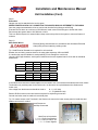
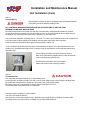
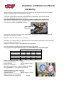
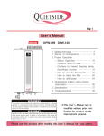
CHG-IOM-001 MAR-06
Installation and Maintenance Manual
Report all Shipping Damage to Carrier IMMEDIATELY, Check units and box exterior for damage
Note to Installer
This manual to is to aid the qualified HVAC contractor in the Installation and Maintenance of this Quietside
R410a Ductless Mini Split
Please read and understand these instructions prior to installing the unit, failure to comply with these
instructions may result in improper installation, operation and maintenance, possibly resulting in fire,
electrical shock, property damage, personal injury or death
Installers please retain this manual for future reference, please pass warranty registration to end user
If Technical Assistance is required during installation or start up, please visit our website at
www.quietside.com
or call 1-562-699-6066 or 717 243 2535 to speak to a Technical Service Assistant
When calling please have the Model numbers and Serial numbers available
Safety Instructions
Read all the Instructions, Install and apply the system per those instructions
Use the unit only in the manner described in this manual
1 Check Rating Plate for correct system voltage before installing the unit
Installing and operating a unit with the incorrect voltage may result in malfunction or
other issues and will void the warranty
2 Units must be connected to a correctly grounded Electrical Supply
3 Do not use the units if they have been dropped or otherwise damage or installed
incorrectly
The manufacturer of the unit will not be liable for any damages caused by failure to comply with the
installation and operating instructions in this manual
The unit Rating Plate contains pertinent information to the unit operation, please refer to it as required
This symbol is an indication of Important Safety Information
Completely read all Instructions prior to assembling installing,
operating, or working on these units
Inspect all parts for damage prior to installation and start up
Units must be installed by a Qualified HVAC Contractor
Installation and Maintenance Manual
Installer Supplied Items
Refrigerant Line Set : Flare Connection only, suitable for R410A with both lines insulated, max length 45ft
Main System Breaker : Sized per unit requirements, to be mounted adjacent to Outdoor unit
High Voltage Interconnect Wiring : 14 AWG wiring from Outdoor unit to Indoor unit for Power and Control
Mounting Hardware : Wall Anchors, Condenser Pad etc
Refrigerant : R410A required for additional line set charge
Condensate Piping : Per local codes to remove condensate from the indoor unit
Items for Consideration
Application
Check the application of the unit prior to installation, certain applications require additional components or
installation parameters
Computer or Data Server Rooms,
These require ballpark sizing of approximately 12,000 Btu/h Capacity per 250 SqFt of room size
The units will be running 24/7, so a Low Ambient Head Pressure Controller (See accessories), a Crankcase
Heater and possibly a Wind Baffle (Field Supplied for cooling below 32 DegF) must be installed
Offices and Commercial Spaces, Churches etc
These require ballpark sizing of approximately 12,000 Btu/h Capacity per 400 SqFt of room size
The units could have the possibility of providing cooling with ambient's below 65 DegF, so a Low Ambient
Head Pressure Controller (See accessories) is required as is a Crankcase Heater (field supplied)
Residential, Bedrooms, Family Rooms etc
These require ballpark sizing of approximately 12,000 Btu/h Capacity per 600 SqFt of room size
Low Ambient is typically not needed, unless a home office application is required.
Heat Pumps are a great application, however the units do not feature any back up resistance heat, so we
do not recommend their use as a primary source of heat in areas where the winter temperatures fall below
25 DegF.
Installation
Determine the best location for mounting the Indoor unit, it must be located a minimum of 4 ft from the floor
Pay attention to the air circulation in the room, 9 & 12k units throw air 15ft, 18 & 24k units throw air 25ft, ensure
no obstacles to airflow exist
Locate the Indoor and Outdoor units as close together as possible, maximum line set run and lift CANNOT
BE EXCEEDED, then determine how the Interconnect piping, wiring and condensate hose is to be run
Unit
QSCE-09/12
QSCE-18/24
QSHE-09/12
QSHE-18/24
Max Line Set Run
50 Feet
50 Feet
50 Feet
50 Feet
Max Vertical Lift
20 Feet
20 Feet
20 Feet
20 Feet
Line Sizes
1/4" & 1/2"
3/8" & 5/8"
1/4" & 1/2"
3/8" & 5/8"
Ensure that all panels can be removed for service as required
Certification
All Quietside Ductless Mini Splits are certified by UL under UL standard 1995 in both Canada and the US
Performance is certified by our certification under the ARI 210/240 Program
Installation and Maintenance Manual
Controls and Components
Units are supplied with a wireless remote controller, which communicates with the unit Microprocessor controller
The return air temperature sensor mounted on the unit then controls the unit operation
Several modes of operation are available to the end user depending on the type of comfort required
All unit operating functions are controlled via the remote controller
Unit operating modes are :
Optional Controls and Components
Low Ambient Controller : ICM 326H must be used in Data Room or Commercial applications
For a wiring diagram please contact Quietside or follow general diagram supplied with ICM Controller
Probe must be located in the fin pack or on a return bend that measures approx 100 DegF during normal
operation
Condensate Pump : Field Installed Mini Pump, Quietside recommend the Aspen brand of Condensate
Pump, follow their wiring diagram recommendations. This pump is installed externally to the unit
Unit Installation
Follow Instructions, failure to follow instructions may cause
possible malfunction and void any warranty
Step 1
Remove Indoor and Outdoor units from the carton/box
Indoor unit carton contains Remote Control and Batteries, ensure these are kept in a safe place during
installation
Step 2
Locate area to Install Indoor unit
Indoor unit must be located a minimum of 4ft from the floor and 6" from the ceiling
Choose an area where the wall is plumb and determine how to best to run the unit interconnects
4" from ceiling
8" from wall
8" from wall
Indoor Unit
Minimum 4ft from floor
Optimum 6ft plus from floor
Ensure no obstacles to Airflow are directly in front of the unit, for a minimum of 12ft for 9/12,000 Btu/h units
and 16ft for 18/24,000 Btu/h units
Do not install the Indoor unit units in areas exposed to high humidity (RH of 80% plus), direct sunlight and
direct heat from stoves or other devices
Installation and Maintenance Manual
Unit Installation (Cont)
Step3
Drill Hole for Line Set etc
Remove mounting bracket from the rear of the Indoor unit,
use a Phillips head screwdriver to remove the unit pipe strap, and if
unit is a heat pump the defrost sensor also must be undone from its
retainer. If mounting the unit on an outside wall measure from the
edges of the unit to the center of the line set stub 90° bend to locate the
the center of the wall penetration. Drill a ø 3" hole through the wall
Angle the wall penetration slightly down towards the outside to
assist in draining the condensate away from the unit
If mounting the unit on an inside wall, use the knockouts provided on the LHS and RHS of the unit to route the
piping and wiring connections through
Step 4
Install Mounting Bracket
Locate and secure the mounting bracket to the wall, the Indoor unit
weighs a maximum of 20Lbs, use wall anchors and mount to a wall stud
to ensure that the wall is capable of holding the weight of the unit
Use a level to ensure mounting bracket is leveled, so condensate can
drain properly
Step 5
Prepare Unit Line Set Connections
Rotate refrigerant line stubs set gently through 90° (if mounting on an outside wall), for other line set
configurations align the stubs as required
Tip : Use Duct tape to tape the Condensate hose (make sure it is below the Line set stubs) and the Defrost
Sensor (Heat Pump Only), this makes it easier to guide them though the hole drilled in the wall
Also if possible feed the 14 AWG Interconnect wiring between Indoor and Outdoor (Maximum # of
wires required is 6) through the unit electrical connection (if required by local codes an electrical connector
can be attached to the rear of the unit). Tape the loose wire to the line set stubs.
These two tips save time and prevent damage to the stubs when mounting the Indoor unit
Note :
Condensate hose is taped below line set stubs
Wrap Duct tape to the end of the condensate hose for easier
installation
Installation and Maintenance Manual
Unit Installation (Cont)
Step 6
Install unit on Mounting Bracket
Feed the line set stubs/condensate hose/wiring connections through
the ø 3" hole, then locate the unit key slots onto the tabs on top of
the mounting bracket. Bottom of the unit then latches onto the
mounting bracket. Indoor unit is now installed, it should be plumb,
level and flush with the wall. If it is not check that the line set stubs
are completely through the wall penetration, and also that the wall is plumb
Step 7
Locate Outdoor unit
Clearances for the Outdoor unit are :
6" Minimum
Outdoor Unit
6"
Minimum Front
Condenser Fan
Rear
Service
Valves
12"
Minimum
Install the Outdoor
unit on a Condenser
Pad or if a Heat
Pump use feet to
raise unit up approx
6" to allow for
defrost to drain away
24" Minimum
Do not install the Outdoor unit in a location exposed to high winds (field fabricated and installed wind baffle
may be required).
Ensure location does not impede access around unit and pose a disturbance to neighboring areas
Step 8
Refrigerant Line Set Piping
Interconnecting line set between the Outdoor unit and the Indoor unit, must have both refrigerant lines
insulated as condensing device is located in the Outdoor unit
Gently bend the line set stubs from the Indoor unit to the desired location
Using 2 x 10"/12" Crescent wrenches remove the flare nuts from the Indoor unit line stubs. Unit is filled with
a dry gas, check for release of this to ensure that no leaks are present
Use a small amount of vacuum pump oil on the male flare threads to ease installation. Connect the line set to
the stubs. Using the 2 wrenches, 1 on the male & 1 on the female tighten the flare nuts
DO NOT INSTALL A LIQUID LINE SIGHT GLASS OR FILTER DRIER IN THE SYSTEM
Run the line set to the Outdoor unit, avoid tight bends and kinking the lines. Quietside does not recommend
brazing line sets together or to the unit connections
If line set length is in excess of that required, cut line set and re-flare or coil excess vertically to facilitate oil
return to the compressor
Installing the
Line Set on the
Indoor unit
stubs
Line Set Connections
under the GRAY caps
Installation and Maintenance Manual
Unit Installation (Cont)
Step 9
Evacuation
Gauges can now be attached to the service ports SERVICE PORTS HAVE A 5/16" CONNECTION TO GAUGES, WHICH IS DIFFERENT TO THE NORM
Once the gauges are attached the line set can be leak checked using Nitrogen at 300 Psig
Evacuate the unit down to a minimum of 200 Microns, break vacuum with Nitrogen to further leak check
Re-evacuate the system down to 200 Microns or lower
This is an R410A System it is essential that a deep vacuum be pulled on the system to remove all traces of
moisture
Step 10
Main Power Wiring
Electrical Wiring should be done in accordance with all National Electrical
Code (NEC) and local state/city building codes
Tip : Small Electrical Screwdriver is required for unit terminals
Breaker size and wiring must be sized for the rating plate amperage, MCA and MOP
If a smaller than required breaker is used possibility of unit damage etc could occur
Use only HACR type breakers, each system installed must have a separate branch circuit with an individual
breaker/fuse
Breaker Size
RLA
MCA
QCIC-09
15A
6.7A
8.2A
QCIC-12
15A
8.8A
10.8A
QCIC-18
15A
5.3A
6.5A
QCIC-24
20A
8.6A
10.6A
Breaker Size
RLA
MCA
QCIH-09
15A
6.9A
8.4A
QCIH-12
15A
9.0A
11.0A
QCIH-18
15A
5.5A
6.8A
QCIH-24
20A
8.6A
10.6A
A local disconnect should be installed adjacent to the Outdoor unit in accordance with National and Local Codes
The Outdoor unit provides power for the Indoor unit, no disconnect is required between the Outdoor and
Indoor units
Line voltage from the disconnect should be wired to
N - L (115V Unit)
L1 - L2 (208/230V Unit)
Remove RHS Knockout on the terminal access panel for whip/wiring connection
Ground connection must be made to the terminal plate
Tip : For easier access to the Terminals in the Outdoor unit remove the lower access panel to install whip and
sealtite connectors for conduit
Local Disconnect
and Whip Connected
Heat Pump unit terminals
L1 - L2 : Power from Breaker
L3 - L4 : Power to Indoor unit
1 - 2 - 3 : Control Signals
Installation and Maintenance Manual
Unit Installation (Cont)
Step 11
Controls Wiring
Electrical Wiring should be done in accordance with all National Electrical
Code (NEC) and local state/city building codes
ALL CONTROLS WIRING BETWEEN INDOOR AND OUTDOOR UNIT IS HIGH VOLTAGE
MINIMUM 14 AWG WIRE MUST BE USED
Remove terminal covers from Indoor unit and wire to the terminals, small electrical screwdriver required
Control wiring from the Outdoor Unit must be a point to point i.e. the terminal that the wire is attached to on
the Outdoor unit must be the same terminal it is wired to in on the Indoor unit
This is extremely important : Switching the L3 - L4 or N1 - L1 wires over will allow the Indoor unit to operate but
it will not provide controls signals for the Outdoor unit so that the compressor will not operate
Ground connection should be made to ground screw marked in Indoor unit
If unit is a Heat Pump Defrost Sensor must be connected from the Indoor unit to the Defrost Sensor in the
Outdoor unit. Standard lead length is 25ft, if a longer length is required then cut the lead and extend using
thermostat wire
Control Wiring at Outdoor unit (Heat Pump unit shown)
Note use of colored wire (supplied with Line Set) and defrost
sensor connected (Heat Pump only)
Ground wires connected to the terminal plate
Indoor and Outdoor units must be grounded
Step 12
Condensate Hose
Unit is provided with approximately 18" of Condensate Hose
Hose connection is sized to accept a 3/4" OD or 5/8" ID Clear Plastic Hose to then extend to building drain
All condensate hose extensions should be in accordance with local building codes
Remember water only flows downhill to ensure positive draining from the unit
Check using water for a positive flow of Condensate
The basic system installation is now complete
The unit is now ready for start up Use this time to ensure that worksite is tidy. Quietside recommend the use of Slimduct products to hide
the refrigerant line set interconnects - available from your Quietside distributor
Installation and Maintenance Manual
Unit Start Up
With the refrigerant system completely evacuated the system can now be opened to allow the refrigerant
charge in the Outdoor unit to be released into the line set
The Service Valves require a 6mm and a 5mm Allen wrench respectively to undo the valve stems
Remove the BRASS caps from the Service Valves
Open the SUCTION line Valve first to prevent any possible oil logging of the Capillary tube
This can occur if the liquid line valve is opened first with the rest of the system in a deep vacuum
Then open the "LIQUID or EXPANDED GAS" line
Open Suction Line
Valve First
Unscrew both valve stems until they come to a stop against the valve body, replace the Brass Caps and
then tighten the caps to prevent leaks
Energize the breaker to allow system to be powered
Start Indoor unit, Cooling mode is only allowed when the Outside Ambient Temperature is above 65 DegF to
prevent damage to the compressor
Unit has a 3 minute time delay for the compressor start up operation
Unit is charged with enough R410A refrigerant for a line set of 25ft length
For longer line set lengths additional charge must be WEIGHED in per the following table
Unit
QCIC-09 & 12
QCIC-18 & 24
QCIH-09 & 12
QCIH-18 & 24
Added Charge required for a line set of
30ft
35ft
40ft
45ft
1.5oz
3.0oz
4.5oz
6.0oz
2.5oz
5.0oz
7.5oz
10.0oz
1.5oz
2.5oz
3.0oz
5.0oz
4.5oz
7.5oz
Standard Operation of the unit - Cooling
Indoor Temperature Split
30 DegF
Suction Pressure
115 Psig, approx 37 DegF
Suction Line Temperature
45 DegF
Schraeder connection on the "Liquid" line DOES NOT READ
HEAD PRESSURE - it is an expanded gas pressure
Standard Operation of the unit - Heat Pump
Indoor Temperature Split
30 DegF
High Side Pressure
400 Psig, approx 117 DegF
(Measured at Liquid Line Schraeder)
Discharge (Liquid) Line Temperature
130 DegF
6.0oz
10.0oz
Installation and Maintenance Manual
Wiring Diagrams