1
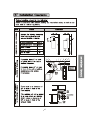
DPW-099 DPW-120
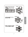
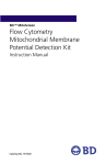
Bottom of DPW-099A and DPW-120A
DPW
DPW
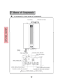
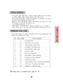
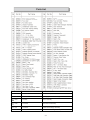
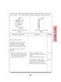
Product Specifications
DPW-099A
Heating System Data
Heat Input (Btu/h)
AFUE (%)
Htg Water Temp (DegF)
Working Pressure (psi)
Freeze Protection Device
Heating Min Flow (GPM)
Htg Heat Exch Water Volume (gal)
Ignition Type
Domestic Hot Water
DHW Production Energy Factor
Temperature Setting
DHW Minimum Flow Rate (GPM)
GPM at 50F in 100F Out
GPM at 50F in 110F Out
GPM at 50F in 120F Out
GPM at 50F in 130F Out
General Data
Control Voltage
Fuel Type
Natural Gas Inlet Press ("WC)
LP Gas Inlet Pressure ("WC)
Gas line Size (inch)
Unit Voltage (V)
Power Consumption (W)
Pump Flow @ 10ft Head
NOX Levels (ppm)
DPW-120A
47,800 - 99,000
47,800 - 120,000
90
90
122 to 176 DegF leaving unit Heat Exchanger
15 - 20
Thermistor, will energize pump/combustion
1.2
0.2
0.2
Electronic Spark
0.83
0.85
Controlled : Settings of 98 - 114°F, 120°F, 130°F, 140°F
GPM
0.5 0.7
to 0.7
GPM
3.7
4.5
3.1
3.7
2.6
3.2
2.3
2.8
24V DC - Requires X-X or Zero Voltage Contact for Zone applications
NG or Field Conversion to LP
Minimum 5.8"
9.7" WC
WC
3.5" WC to Maximum 10.5"
Minimum 9"
8" WC to Maximum 13" WC
Min Size 3/4"
115V-1Ph-60Hz
120
140
2.5 GPM
20
20
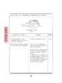
Venting
Max Flue Temp (DegF)
136
Venting Material
Ø3" Schedule 40 PVC
Max Vent Length (feet)
45ft Equivalent each for both Intake and Exhaust
Max number of Elbows*
3 per Individual Vent pipe
*One Elbow = 5 ft equivalent length, which must be deducted from the total vent length
Dimensions
Weight (lbs)
Unit Height (less vent conns) (")
Width (")
Depth (")
Gas Connection Size (")
Heating Supply/Return (")
DHW Inlet/Outlet (")
Flue/Air Intake (")
70
27 5/8"
18 1/8"
8"
70
27 5/8"
18 1/8"
8"
3/4"
3/4"
1/2"
Vent Connection ø3.5" to accept 3" PVC
Quietside maintains a policy of continuous product development and specifications can change
Quietside West : 8750 Pioneer Blvd, Santa Fe Springs CA 90670 : Tel 562 699 6066, Fax 562 699 4351
Quietside East : 6 Pine Hill Drive, Carlisle PA 17013 : Tel 717 243 2535, Fax 717 243 7917
www. Quietside.com
27
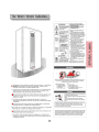
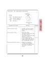
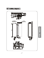
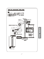
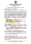
Isometric View - DPW-099 & 120
User's Manual
28
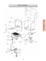
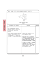
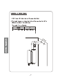
Burner Assembly
User's Manual
29
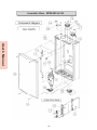
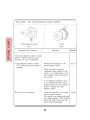
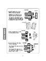
Water Line
User's Manual
30
Parts List
User's Manual
1R
3DUW1R
3DUW1DPH
6
3&%DVVHPEO\
6
6SDUNSOXJ)ODPHURGVHQVLQJURG
%XUQHUDVVHPEO\
6
*DV9DOYH$6$VVHPEO\
6
/DWHQWKHDWH[FKDQJHUDVVHPEO\
6HQVLEOHKHDWH[FKDQJHUDVVHPEO\
31
43
44
45
46
47
48
DPW
DPW Models
49
DPW-099A
50
DPW-120A
DPW-099A
DPW Unit
51
DPW
52
DPW
53
54
DPW
55
56
DPW
57
DPW
DPW
DPW
DPW
58
59
60
(2) Factory Installed Brown
Zone Control Wires Attached
To Terminals 9 & 12
61
62
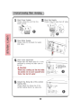
DPW Dip Switch Settings
Depending on the application of the DPW unit it may be necessary to alter the
Dip Switch settings from the standard positions
The unit has 5 Dip Switches located on the Microprocessor
Dip Switch
1
2
3
4
5
Standard Setting
ON
OFF
OFF
OFF
OFF
Controls
Fuel Gas Type
Fuel Gas Type
Unit Options
Forced Maximum Firing rate
Forced Minimum Firing rate
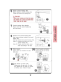
Setting for Natural Gas Operation
Dip Switch
Setting for NG
1
ON
2
OFF
Setting for LP Gas Operation
Dip Switch
Setting for LP
1
OFF
2
ON
Unit Options
Switch Dip Switch #3 to ON
On DSR-100F press the Timers and Anti Freeze buttons simultaneously for 5
seconds. This will allow unit to enter the programming mode
Temperature display can be changed between DegF and DegC by pressing the
Timer button 3 times until Lc is displayed in the top RH corner of the unit display,
and f is displayed in the center of the screen
Press the Up temperature arrow and the f will change to a c
Hit the Power On/Off button to exit and switch Dip Switch #3 to OFF, the unit will
now display in DegC
63
Cont
Zone Control
This can be also be set up using this control (see zone control wiring section for
more detail)
Maximum Firing Rate
Setting Dip Switch #4 to ON will lock the unit into the maximum firing rate at all
times. This is occasionally used for troubleshooting and gas pressure set up
purposes. Move the switch back to OFF to allow the unit to modulate capacity
Minimum Firing Rate
Setting Dip Switch #5 to ON will lock the unit into the minimum firing rate at all
times. This is occasionally used for troubleshooting and gas pressure set up
purposes. Move the switch back to OFF to allow the unit to modulate capacity.
64
Specific requirements for installation in Massachusetts
In the Commonwealth of Massachusetts these units must be installed by a
licensed gas fitter or plumber
Venting :
For the Quietside models DPW-099A, DPW-120A where the bottom of the vent
termination and combustion air intake is installed at a height BELOW 4 ft above
the grade level the following requirements must be satisfied
1. If there is not one presently installed, on each floor level where there is a
bedroom(s), a Carbon Monoxide detector and alarm shall be installed in
the living area outside the bedroom(s). The Carbon Monoxide detector
shall comply with NFPA 720 (2005 Edition)
2. A Carbon Monoxide detector shall be installed in the room where the
ODW unit is installed, the detector shall be :
a) Powered from the same power circuit that provides power for the ODW
unit. A single electrical service switch shall be used to service both the
unit and the detector
b) Have battery back up power
c) Meet ANSI/UL std 2034 and comply with NFPA 720 (2005 Edition)
d) Approved and listed by a NRTL recognized under 527 CMR
3. A Quietside approved vent termination must be used. Installation of the
vent terminal must be in strict compliance with Quietside’s written
instructions, and a copy of these instructions must remain with the unit
after the installation is completed.
4. A metal or plastic identification plate shall be mounted on the exterior of
the building, 4ft above the vent termination. The plate shall read “Gas
Vent Directly Below” with text size visible from a minimum of 8ft.
65
Cont
For the Quietside models listed above where the bottom of the vent termination
and combustion air intake is installed at a height of 4ft ABOVE the grade level
the following requirements must be satisfied
1. If there is not one presently installed, on each floor level where there is a
bedroom(s), a Carbon Monoxide detector and alarm shall be installed in
the living area outside the bedroom(s). The Carbon Monoxide detector
shall comply with NFPA 720 (2005 Edition)
2. A Carbon Monoxide detector shall be installed in the room where the
ODW unit is installed, the detector shall be :
a) Powered from the same power circuit that provides power for the ODW
unit. A single electrical service switch shall be used to service both the
unit and the detector
b) Have battery back up power
c) Meet ANSI/UL std 2034 and comply with NFPA 720 (2005 Edition)
d) Approved and listed by a NRTL recognized under 527 CMR
3. A Quietside approved vent termination must be used. Installation of the
vent termination must be in strict compliance with Quietside’s written
instructions, and a copy of these instructions must remain with the unit
after the installation is completed.
Vent Termination requirements
As the DPW unit is a condensing product
The Vent for all Quietside DPW units shall not terminate
Over Public Walkways; or
Near soffit vents or crawl space vents or other area where condensate or vapor
could create a nuisance or hazard or cause property damage; or
Where condensate or vapor could cause damage or could be detrimental to the
operation of regulators, relief valves, or other equipment
66
Specific requirements for installation in Canada
The provinces of Ontario and Alberta have adopted standard ULC S636 requiring
the following additional items to be noted.
1. Maximum flue temperature as tested is 136 DegF, allowing these
units to be vented with Schedule 40 PVC under the regulation of
ULC S636.
2. Under the new requirements of ULC S636 regarding vent
connections to the unit, Quietside requires the Schedule 40 Vent
piping to be secured to the unit using approved PVC cement,
following the cement manufacturers instructions regarding
methodology and curing time. A bead of high temperature silicone
should be also run around the joint to ensure no leaks can occur.
Silicone
seal
67
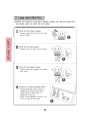
Combustion and Leak Testing of DPW units
As the front cover of the unit is mechanically attached and cannot be removed in
operation without the use of a tool, it is not permissible to conduct combustion
testing or leak testing of the unit with the front cover removed.
Combustion testing must be achieved by using a calibrated combustion tester,
with the probe inserted either in the flue exhaust of the vent termination or it is
permissible to take reading by accessing the flue pipe approximately 12” above
the unit, providing adequate provisions are made for sealing any access after
testing to ensure no leakage of flue gases into the occupied space.
Leak testing must take place with the end of the “sniffer probe” at least 1” from
any surface of the unit to ensure that false readings cannot be obtained.
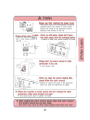
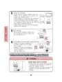
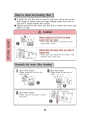
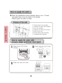
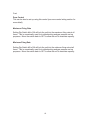
Auto Fill – Closed Loop System
The DPW unit is fitted with a MANUAL Auto Fill valve, supplied in the closed
position.
The Fill Valve is not pressure regulated therefore care must be used when
opening the valve to prevent overfilling of the closed loop system and opening of
the pressure relief valve.
Quietside recommends that the valve be left in the closed position and an
external Boiler Feed Valve e.g. Taco 335/329 be installed in the piping system to
maintain an even pressure in the closed loop system
Manual Auto Fill Valve located on base of cabinet
68
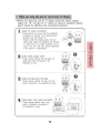
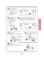
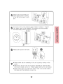
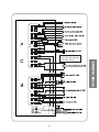
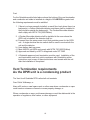
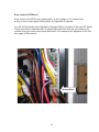
Zone control of DPW unit
Zone control of the DPW unit is performed by a zero voltage or X-X contact from
a relay or zone control panel closing when unit operation is required.
You will find two brown wires attached to the upper Molex connector of the main PC board.
These wires can be extended with 18 gauge thermostat wire and only connected to dry
contacts from your zone control panel end switch. See example wire diagrams on the last
four pages of this manual.
Brown Wires
69
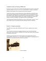
Anti Freeze & Freeze Protection
For Anti Freeze protection in the Quietside units the following products are
recommended
“No Burst”
“Fernox Alphii”
The maximum concentration allowed is 30% by volume which will protect the unit
down to approximately 5 DegF or -11 DegC
Water Quality
DPW models potable side must have the water quality within the following limits
for long life and reliable operation. The water supply should be tested to make
sure the quality is within specified limits. If there is a problem with the water
quality, contact your local water conditioning company for equipment to condition
the water supply to these appliances.
Operating this water heater with water conditions outside the specified limits will
void the warranty.
Description
PH
TDS
(Total
Dissolved
Solids)
Total
Hardness
Aluminum
Chlorides
Copper
Iron
Manganes
e
Zinc
Maximum
Levels
6.5 to 8.5
Up to
500 ppm
Up to
200 ppm
or 11.7
grains
hardness
Up to
0.2 ppm
Up to
250 ppm
Up to
1.0ppm
Up to
0.3 ppm
Up to
0.05ppm
Up to
5 ppm
70
Pump Curves & Primary – Secondary Piping
The DPW units include a pump assembly that is used to provide the flow through
the unit heat exchangers, and has a nominal flow of heating water for external
piping arrangements.
This pump is not designed to be the system pump providing flow to radiant loops
or baseboard.
Therefore Quietside insists on using a Primary – Secondary pumping
arrangement, the recommended method uses the traditional large diameter
Primary loop
The main circulation pump or the zone pumps will then provide circulation into
the zones or the heating system
The only exception to this Primary – Secondary rule is for Air Handling units with
a hot water coil where the Air Handling unit is located less than 10ft from the
DPW unit.
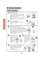
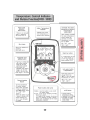
Unit Controls & Zoning
A DSR-100F Controller is provided with the unit.
This is not used as a thermostat, but is a unit controller and should be mounted
adjacent to the DPW unit. It is connected to the DPW via the 2 Yellow wires and
is powered by 20V DC.
The DSR controller allows both the heating loop and DHW water temperatures to
be set
When the unit is started using the X – X or dry contacts on the microprocessor it
will operate and provide heating loop water at the set temperature until the
zone(s) are satisfied. If a DHW call is experienced during heating operation the
unit will automatically switch over to provide DHW.
DO NOT APPLY 24V AC OR LINE VOLTAGE TO THE X – X CONTACTS
UNIT MICROPROCESSOR WILL FAIL IF IT RECEIVES 24V AC OR LINE
VOLTAGE ON THESE CONTACTS
It is not permissible to power the secondary loop pump from the Primary loop
pump installed in the unit.
Power for the Secondary loop pump should come from a switching relay e.g
Taco SR501
71
72
DHW
Hot Out
Closed
Loop
Supply
3/4" Unions to connect
to 3/4" Male Supply and Return
connections on DPW
DHW
Cold In
DPW UNIT
Supply to Heating
zones
(No detail shown)
Return from Heating
zones
(No detail shown)
House
Hot Water
Supply
Tel : 562 699 6066, Fax : 562 699 4351, Web : www.Quietside.com
8750 Pioneer Blvd, Santa Fe Springs CA 90670
System Circulation Pump
Field Installed
Air Vent at
highest point
Anti Scald Valve
MANDATORY
Set for Maximum
of 120DegF
Boiler drain installed on Primary Loop
should be below DPW Isolation valve to allow
closed loop system to be filled with DPW
isolated from the closed loop to protect unit
A Drain can also be installed on return piping above
shut off valve to drain the unit or Pressure Relief
valve on the unit can be used provide a drain
Check system design for requirement for
additional expansion tank on closed loop system
Notes :
When brazing always wrap valves, drains
etc with a wet rag to prevent damage
Title : DPW Recommended Piping Layout, Heating & DHW
Drg # : QUI-DPWP-001 Drawn : JLM 8/26/2008
Rev : 001
2 x 1 1/4" x 1 1/4" x 3/4" Tees
Space max of 4 Pipe Dia's
apart on tee centerline
Closed
Loop
Return
Use 1 1/4"
pipe diameter
for heating
primary loop
"Boiler Drain" - see notes
Shut Off Valves to isolate
both Supply & Return
Boiler Feed Valve with
Backflow prevention
See local codes
Pressure Relief Valve
(Factory Supplied)
Pipe to building drain
(See local codes)
"Boiler Drains" to allow
maintenance of the DHW
Plate Heat Exchanger
Shut Off Valves to isolate
both Inlet and Supply of
DHW system from DPW
Cold Water Supply
from House to 1/2"
male connection on
DPW
Use 1/2" Unions
73
Closed
Loop
Return
Use max ø1" pipe for Supply
& Return to AHU. Max total pipe
length (Supply & Return) 20ft
"Boiler Drain" - see notes
Shut Off Valves to isolate
both Supply & Return
Boiler Feed Valve with
Backflow prevention
See local codes
Pressure Relief Valve
(Factory Supplied)
Pipe to building drain
(See local codes)
"Boiler Drains" to allow
maintenance of the DHW
Plate Heat Exchanger
Shut Off Valves to isolate
both Inlet and Supply of
DHW system from DPW
Cold Water Supply
from House to 1/2"
male connection on
DPW
Use 1/2" Unions
DHW
Hot Out
Closed
Loop
Supply
8750 Pioneer Blvd, Santa Fe Springs CA 90670
Air Handler should not have
it's own circulator installed
Disconnect pump if installed
System is designed for the
Air Handler to be located no
more than 10ft from the DPW
and no more than 5ft above
or below the DPW
Coil Inlet
House
Hot Water
Supply
Tel : 562 699 6066, Fax : 562 699 4351, Web : www.Quietside.com
AHU
Unit
HW Coil
Air Vent at
highest point
Anti Scald Valve
MANDATORY
Set for Maximum
of 120DegF
A Drain can also be installed on return piping above
shut off valve to drain the unit or Pressure Relief
valve on the unit can be used provide a drain
Boiler drain installed on piping
should be below DPW Isolation valve to allow
closed loop system to be filled with DPW
isolated from the closed loop to protect unit
Title : DPW Recommended Piping Layout, AHU (No Pump) & DHW
Drg # : QUI-DPWP-002 Drawn : JLM 8/26/2008
Rev : 001
3/4" Unions to connect
to 3/4" Male Supply and Return
connections on DPW
DHW
Cold In
DPW UNIT
Notes :
When brazing always wrap valves, drains
etc with a wet rag to prevent damage
74
Air Vent at
highest point
3/4" Unions to connect
to 3/4" Male Supply and Return
connections on DPW
Closed
Loop
Return
DHW
Hot Out
Closed
Loop
Supply
ø3/4"NPT
ø3/4"NPT
Cold Water Inlet
from House supply
ø1" NPT
Title : DPW Piping, Primary Loop Htg c/w QSDHS DHW Storage
Drg # : QUI-DPWP-003 Drawn : JLM 9/18/2008
Rev : 001
Tel : 562 699 6066, Fax : 562 699 4351, Web : www.Quietside.com
8750 Pioneer Blvd, Santa Fe Springs CA 90670
QSDHS
DHW STORAGE
TANK
SYSTEM
20 GAL
CAPACITY
From
DPW DHW
Outlet
Anti Scald Valve
MANDATORY
Supplied with QSDHS
Max Setting 120DegF
ø3/4" NPT Connection
House
Hot Water
Supply
QSDHS DHW System Notes :
Tank system also includes Tank Drain and
P/R Valve (supplied loose)
These should be installed and piped in
accordance with local codes
DPW DHW Inlet &
Outlet connection
sizes are 1/2"
Taco 008 Bronze Pump
c/w IFC and Shut offs
Supplied with QSDHS
Shut Off Valves to
isolate DPW
from Air Handler
To DPW
DHW Inlet
DHW
Cold In
DPW
DPWH
Supply to Heating
zones
(No detail shown)
Return from Heating
zones
(No detail shown)
Secondary or Zone Pump
Use ø1 1/4" pipe
for Primary Loop
"Boiler Drain" - see notes
Pressure Relief Valve
Pipe to building drain
(See local codes)
Boiler drain installed on Supply to closed loop
should be below DPW Isolation valve to allow
closed loop system to be filled with DPW
isolated from the closed loop to protect unit
A Drain can also be installed on return piping above
shut off valve to drain the unit or Pressure Relief
valve on the unit can be used provide a drain
Check system design for requirement for
additional expansion tank on closed loop system
Closed Loop Heating System Notes :
When brazing always wrap valves, drains
etc with a wet rag to prevent damage
75
Air Vent at
highest point
Closed
Loop
Return
AHU
Unit
HW Coil
Use max ø1" pipe for Supply
& Return to AHU. Max total pipe
length (Supply & Return) 20ft
"Boiler Drain" - see notes
Pressure Relief Valve
Pipe to building drain
(See local codes)
3/4" Unions to connect
to 3/4" Male Supply and Return
connections on DPW
Boiler drain installed on Supply to closed loop
should be below DPW Isolation valve to allow
closed loop system to be filled with DPW
isolated from the closed loop to protect unit
A Drain can also be installed on return piping above
shut off valve to drain the unit or Pressure Relief
valve on the unit can be used provide a drain
System is designed for the Air Handler to be located
no more than 10ft from the DPW and no more
than 5ft above or below the DPW
Closed Loop Heating System Notes :
When brazing always wrap valves, drains
etc with a wet rag to prevent damage
To DPW
DHW Inlet
DHW
Hot Out
Closed
Loop
Supply
Cold Water Inlet
from House supply
ø1" NPT
8750 Pioneer Blvd, Santa Fe Springs CA 90670
QSDHS
DHW STORAGE
TANK
SYSTEM
20 GAL
CAPACITY
Anti Scald Valve
MANDATORY
Supplied with QSDHS
Max Setting 120DegF
ø3/4" NPT Connection
Tel : 562 699 6066, Fax : 562 699 4351, Web : www.Quietside.com
ø3/4"NPT
ø3/4"NPT
From
DPW DHW
Outlet
DPW DHW Inlet &
Outlet connection
sizes are 1/2"
House
Hot Water
Supply
Title : DPW Piping, Close coupled AHU c/w QSDHS DHW Storage
Drg # : QUI-DPWP-004 Drawn : JLM 9/18/2008
Rev : 001
Taco 008 Bronze Pump
c/w IFC and Shut offs
Supplied with QSDHS
Shut Off Valves to
isolate DPW
from Air Handler
DHW
Cold In
DPW
DPWH
QSDHS DHW System Notes :
Tank system also includes Tank Drain and
P/R Valve (supplied loose)
These should be installed and piped in
accordance with local codes
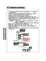
76
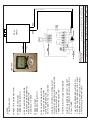
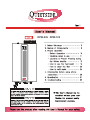
THIS IS THE PREFERRED METHOD TO
CONTROL THE SECONDARY LOOP PUMP
REQUIRED IN ALL NON CLOSE COUPLED
AHU & HW COIL APPLICATIONS
WHEN THE ZONE(S) SATISFY THE UNIT
WILL SHUT DOWN, DSR WILL REMAIN LIT
AT ALL TIMES
DHW PRIORITY WILL BE MAINTAINED
WHEN X-X CONTACT IS CLOSED UNIT
WILL START AND PROVIDE CLOSED LOOP
HEATING WATER AT THE
TEMPERATURE SELECTED
5 USE UP AND DOWN ARROWS
TO SELECT DESIRED DHW
WATER TEMPERATURE
98-114 DEGF, 120, 130, 140 DEGF
4 PRESS DHW SET
TEMPERATURE BUTTON
3 USE UP AND DOWN ARROWS
TO SELECT DESIRED HEATING
WATER TEMPERATURE
RANGE 122-176 DEGF
2 PRESS HEATING SET
TEMPERATURE BUTTON
1 PRESS UNIT ON/OFF BUTTON
NOTES
TO SET DSR-100F
DSR-100F
BRN
Tel : 562 699 6066, Fax : 562 699 4351, Web : www.Quietside.com
8750 Pioneer Blvd, Santa Fe Springs CA 90670
BRN
Title : DPW & TACO SR501 ZONE CONTROL PANEL WIRING
Drg # : QUI-ZCW-003 Drawn : JLM 9/24/2008
Rev : 001
YEL
YEL
DPW
DPWH
77
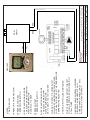
DIAGRAM SHOWS AN SR504, HOWEVER
DIAGRAM CAN BE USED WITH ALL
ZONE CONTROL PANELS (SR, ZV, ETC)
WITH AN X - X OR 0V CONTACT
WHEN THE ZONE(S) SATISFY THE UNIT
WILL SHUT DOWN, DSR WILL REMAIN LIT
AT ALL TIMES
DHW PRIORITY WILL BE MAINTAINED
WHEN X-X CONTACT IS CLOSED UNIT
WILL START AND PROVIDE CLOSED LOOP
LOOP HEATING WATER AT THE TEMPERATURE
TEMPERATURE SELECTED
5 USE UP AND DOWN ARROWS
TO SELECT DESIRED DHW
WATER TEMPERATURE
98-114 DEGF, 120, 130, 140 DEGF
4 PRESS DHW SET
TEMPERATURE BUTTON
3 USE UP AND DOWN ARROWS
TO SELECT DESIRED HEATING
WATER TEMPERATURE
RANGE 122-176 DEGF
2 PRESS HEATING SET
TEMPERATURE BUTTON
1 PRESS UNIT ON/OFF BUTTON
NOTES
TO SET DSR-100F
DSR-100F
BRN
Tel : 562 699 6066, Fax : 562 699 4351, Web : www.Quietside.com
8750 Pioneer Blvd, Santa Fe Springs CA 90670
BRN
Title : DPW & TACO SR504 ZONE CONTROL PANEL WIRING
Drg # : QUI-ZW-002 Drawn : JLM 9/24/2006
Rev : 001
YEL
YEL
DPW
DPWH
78
THIS IS THE PREFERRED METHOD TO
INTEGRATE ZONE VALVES AND
THE SECONDARY LOOP PUMP
WHEN THE ZONE(S) SATISFY THE UNIT
WILL SHUT DOWN, DSR WILL REMAIN LIT
AT ALL TIMES
DHW PRIORITY WILL BE MAINTAINED
WHEN DRY CONTACT IS CLOSED UNIT
WILL START AND PROVIDE CLOSED
LOOP HEATING WATER AT THE
TEMPERATURE SELECTED
5 USE UP AND DOWN ARROWS
TO SELECT DESIRED DHW
WATER TEMPERATURE
98-114 DEGF, 120, 130, 140 DEGF
4 PRESS DHW SET TEMP
BUTTON (RHS OF ON/OFF BUTTON)
3 USE UP AND DOWN ARROWS
TO SELECT DESIRED HEATING
WATER TEMPERATURE
RANGE 122-176 DEGF
2 PRESS HEATING SET TEMP
BUTTON (LHS OF ON/OFF BUTTON)
1 PRESS UNIT ON/OFF BUTTON
NOTES
TO SET DSR-100F
YEL
YEL
BRN
Tel : 562 699 6066, Fax : 562 699 4351, Web : www.Quietside.com
8750 Pioneer Blvd, Santa Fe Springs CA 90670
BRN
DPW
DPWH
Title : DPW & TACO ZVC ZONE CONTROL PANEL WIRING
Drg # : QUI-ZCW-005 Drawn : JLM 10/17/2008
Rev : 001
To Secondary
Pump Control
e.g. Taco
SR501
DSR-100F
79
WHEN T-STAT CALLS FOR HEAT, RELAY WILL
CLOSE AND DPW UNIT WILL START
WHEN T-STAT IS SATISFIED RELAY WILL OPEN AND
UNIT WILL STOP
DSR CONTROL WILL REMAIN LIT AT ALL TIMES
6 INSTALL AN AQUA STAT IN THE HTG COIL
OF THE AIR HANDLER - WIRE TO FAN
MOTOR TO STOP FAN OPERATION IF
COIL TEMPERATURE FALLS e.g. DHW
PRIORITY OR INITIAL START UP
5 USE UP AND DOWN ARROWS
TO SELECT DESIRED DHW
WATER TEMPERATURE
98-114 DEGF, 120, 130, 140 DEGF
4 PRESS DHW SET
TEMPERATURE BUTTON
3 USE UP AND DOWN ARROWS
TO SELECT DESIRED HEATING
WATER TEMPERATURE
RANGE 122-176 DEGF
2 PRESS HEATING SET
TEMPERATURE BUTTON
1 PRESS UNIT ON/OFF BUTTON
TO SET DSR-100F CONTROLLER
NOTES
WIRING DIAGRAM FOR CONTROL OF A
AIR HANDLER & HW COIL, WHERE
PRIMARY PUMP IN DPW IS CAPABLE
OF PROVIDING FLOW TO FAN COIL
W
W
HYDRONIC
FAN COIL
Tel : 562 699 6066, Fax : 562 699 4351, Web : www.Quietside.com
8750 Pioneer Blvd, Santa Fe Springs CA 90670
C
BRN
C
SPST
RELAY
24V AC
BRN
DPW
DPWH
Title : DPW & SPST RELAY CONTROL WIRING
Drg # : QUI-DPW-ZW-001 Drawn : JLM 9/6/2006
Rev : 001
STD 24V AC
HEAT
COOL
TSTAT
YEL
YEL
DSR-100F