1
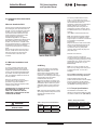
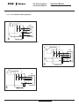
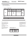
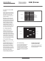
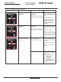
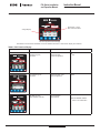
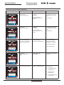
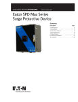
Installation and Operation Manual for Powerware
PXL Series Surge Protective Device
IM 01005001E
For more information visit: www.eatonelectrical.com
Instruction Manual:
IM01005001E
Effective 01.06
Instruction Manual
Page 2
Effective: January 2006
PXL Series Installation
and Operation Manual
PXL Installation Manual
Table of contents
Description
Page
Section 1 Introduction .............................................3
Section 2 Installation Procedure..............................3
Section 3 Operating Features..................................6
Section 4 Troubleshooting ......................................7
Section 5 Warranty and Technical Assistance........15
IM 01005001E
information visit: www.eatonelectrical.com
Effective 01.06
PXL Series Installation
and Operation Manual
Section 1 Introduction
The PXL series of Surge Protective
Devices (referred to as PXL from this
point forward) offer surge protection and
filtering to provide clean power for
sensitive electronic loads. The PXL units
shunt high energy induced lightning
surges, as well as other formats of
transient disturbances. Properly installed
PXL units protect critical equipment in
hospital, commercial, computer
manufacturing, telecommunication,
financial and military facilities.
The PXL removes power disturbances
from electrical distribution systems using
a low impedance shunt path to ground.
Surges and electrical line noise are
absorbed by the PXL and are prevented
from traveling through distribution system
wires to sensitive electronic loads. Prior to
installing the PXL check the units voltage
and configuration to verify it matches your
system voltage and wiring configuration.
WARNING
INSTALLING A PROTECTION DEVICE
WHICH IS UNDER-RATED FOR THE
ELECTRICAL SYSTEM VOLTAGE
CAN CREATE A POTENTIALLY
HAZARDOUS CONDITION
Section 2 of this manual details the
installation procedures for the PXL
Series SPDs.
Section 3 of this manual describes
the operating features for the PXL
Series SPDs.
Section 4 of this manual provides a
detailed troubleshooting guide.
Note: Surge Protective Devices and
Hi-Potential (Hi-Pot) Testing.
CAUTION
CONDUCTING DIELECTRIC OR HIPOTENTIAL TESTING WILL CAUSE
INTERNAL DAMAGE TO SPD UNIT.
DO NOT PERFORM DIELECTRIC OR
HI-POTENTIAL TESTING WITH THE
SPD INSTALLED.
IM 01005001E
Instruction Manual
Page 3 Effective: January 2006
It is common procedure to test distribution
equipment with a form of hi-pot (dielectric
or megger) testing. The hi-pot tester
outputs a high voltage signal at low
current that will shut down if a short
circuits occurs. The principle behind hipot testing is that the high voltage will find
any faults in the distribution system and
then quickly shuts down without
damaging the distribution equipment.
Hi pot testing is usually conducted phase
to phase and phase to ground.
1.1 Surge Protective Device
A Surge Protective Device (SPD) acts
very quickly to suppress high voltages
before they can damage sensitive
electronics. An SPD normally acts in the
nanoseconds range and can withstand
tens of thousands of amps repeatedly.
SPDs are not designed to prevent a
continued overvoltage without damaged.
In order to protect electronics from
damage, an SPD must be connected
from phase to ground. Lightning surges
are almost always shunted to ground and
the SPD must be connected this way to
provide protection.
ground. Because it is easy to miss a
ground connection, it is recommended
that the line and neutral connection are
removed rather than the ground
connection.
1.3.1 Eaton Electrical Specific
Instruction
Eaton Electrical tests each device and
assembly separately for dielectric
breakdown. The assembled SPD has
already been tested at the factory.
Additional tests should not be required.
Due to the possible damage that can
occur, all SPDs have a caution label
applied warning against hi-pot testing of
the assembly. We recommend that hi-pot
testing not be done on distribution
equipment with PXL SPD already
mounted. If hi-pot testing is still going to
be done, it can be accomplished by
following the above instruction and
removing the phases and neutral
connections from the SPD. If all wires to
these terminals are removed, a hi-pot
test can be safely performed. It is very
important to reconnect all wires after the
test. If any wire is left off, it can constitute
a serious hazard or can defeat the
operation of the SPD rendering it nonfunctionial.
1.2 The Problem
During a hi-pot test, the SPD will turn on
and shunt the high voltage to ground. The
hi-pot tester will continue to supply
current until it internally records the fault
condition. By this time, the SPD has been
exposed to a continues current that can
damage the internal components. To
prevent damage, it is critical that hi-pot
testing not be performed on connected
SPDs. From the installers point of view, it
is also important that SPDs are not
connected while performing a hi-pot test
since the SPD will always cause the test
to fail, thus defeating the purpose of the
test.
1.3 Disconnecting SPDs/
Performing Hi-Pot Testing
The only way to perform a hi-pot test in
the presence of an SPD is to disconnect
the SPD from the distribution system. If
the unit is connected through circuit
breaker, the breaker should be shut off as
a first step. This is sufficient for a delta
system to remove the SPD. On Wye
connected systems, the neutral must also
be removed so that all paths to ground
are isolated. An alternative method is to
remove the ground from the SPD before
any hi-pot testing is performed. All
grounds must be removed: the wired
ground, the conduit ground and the case
information visit: www.eatonelectrical.com
Section 2 Installation
Procedures
2.1 Site Preparation
Verify your system application voltage
and wiring configuration is the same as
the enclosed PXL by checking the
voltage rating label located on the PXL
enclosure.
Review the site to ensure the physical
space required to install the PXL exists.
Check the facility grounding system. All
grounding, bonding and earthing must
meet NEC or CEC, as well as any other
applicable national or local codes. A poor
ground or grounding/bonding violations
affect the suppressor’s ability to function
as specified.
CAUTION
PXL TO BE INSTALLED OR
REPLACED BY A QUALIFIED
ELECTRICIAN
Effective 01.06
PXL Series Installation
and Operation Manual
Instruction Manual
Page 4
Effective: January 2006
The unit is provided with 8 knockout
holes - 3 on each side and 2 on the
bottom. Remove the knockout closest to
the intended lead-out form the
panelboard. Install metal conduit (rigid or
flexible) between the unit and the
electrical panel. Run wiring from the
panelboard to the PXL terminals, which
are labeled Phases A, B, C, Neutral and
Ground
(see Table1 recommended wire size).
2.2 Installation Recommendation
for PXL
Where to Install the PXL?
Service entrance applications(switch boards
and switchgear): The optimum location for
the PXL unit is on the load side of the main
breaker. If this is not possible, select the
next closest location. Minimize the lead
length between the suppressor and bus
bars (including the ground bus).
Panelboards applications: for optimum
performance, install the PXL adjacent to the
first breaker after the incoming lug/main
breaker. If this location is occupied, select
the next closest breaker. If no wall space is
available at the side of the panelboard,
locate the PXL directly above or bellow the
panel.
Remove the five screws from the front of
the unit, and lift out the entire front panel.
Mount the device to the wall using the
convenient holes in the back of the
container.
2.3 Minimize Installation Lead
Length
To ensure maximum performance and
best possible protection for connected
equipment, the PXL must be installed as
close to the panel/switchboard/switchgear
as possible. The wire length between the
PXL and installation breaker should be as
short as possible.
Note: For convenience, the PXL is
provided with two sets of terminal lugs to
permit left or right side installation
adjacent to the electrical equipment while
minimizing wiring length.
ONE SIDE ONLY OF THE SPD SHOULD
BE CONNECTED - AN SPD IS A
PARALLEL CONNECTION DEVICE,
ADDITIONAL LOADS SHOULD NOT BE
CONNECTED IN SERIES
Note: Twist and bind together all leads.
Route the wires such that their overall
length is kept to a minimum. This reduces
line impedance and optimizes
performance.
Strip the ends of the wires and terminate
them in the panelboard. Ensure the use
of proper color codes and tighten all
connections. Green or green/yellow
(ground), white (neutral) red (hot), blue
(hot), black (hot).
100 KA
Recheck all connections.
Interior View of the PXL
2.4 Wiring
Turn OFF the power to the electrical
distribution equipment where the PXL
SPD is to be installed.
Install a branch circuit breaker to feed
PXL for ease of installation. The unit
contains UL and CSA approved fusing to
protect against short circuit fault
conditions within the device.
Overcurrent protection is required, (see
Table 1 for required circuit breaker size).
Follow NEC, CEC as well as any other
applicable national or local codes when
connecting the PXL directly to the bus
bar.
Note: 30 ampere circuit breaker or fuses
with a rating of RK5-30 amperes must be
installed ahead of SPD for PXL
applications.
If remote monitoring is employed,
connect the Form C contacts to an alarm
or building monitoring system (such as an
addressable relay). These contact relays
will accept up to 220 VAC, 1A (see
Section 3.2.3).
Note: Form C relay contacts are “fail
safe” and only change state when power
is applied to the PXL, or if the unit is
damaged.
Prior to SPD energization, ensure that
the front cover is securely fastened.
Switch the MAIN power to the ON
position. Switch the branch circuit breaker
supplying the SPD to the ON position.
Ensure all status indicator lights are ON
(see Section 3 Operating Features).
2.7.1 Torque Specifications
All installations must adhere to the
following torque limits regarding the SPD
connection to cable or bus. (See Table 2)
Table 2. Torque Connection
WARNING
TURN OFF POWER SUPPLY BEFORE
WORKING INSIDE
Effective 01.06
Table 1. Required Circuit Breaker &
Wire Size
PXL
Model
Wire Gauge
Required
Circuit Breaker
or Fuse Size
PXL
#10 - 2 AWG
30 Amperes
information visit: www.eatonelectrical.com
Connection type
Phase
Neutral/Ground
Lbs.D Inch (Nm)
55 (6.2)
55 (6.2)
IM 01005001E
PXL Series Installation
and Operation Manual
2.7.2
Instruction Manual
Page 5
Effective: January 2006
PXL Installation Wiring Diagrams
SPD
Figure 1. Single Phase (Split-Phase): 3 Wire + Ground/PE - Voltage Code: 240S
SPD
Figure 3. 3 Phase Wye: 4 Wire + Ground/PE - Voltage Codes: 208Y, 480Y
CPS
Figure 2. 3 Phase Delta: 3 Wire + Ground/PE - Voltage Codes: 240D, 480D
IM 01005001E
information visit: www.eatonelectrical.com
Effective 01.06
PXL Series Installation
and Operation Manual
Instruction Manual
Page 6 Effective: January 2006
2.8 Ordering Guidelines
Table 4. PXL Ordering Guidelines
Catalog #
PXLXXXYYYYZK
PXL
XXX
YYYY
Z
K
Surge Rating
(kA)
100
120
160
200
250
300
400
500
Voltage
Configuration
208Y
240D
240S
480Y
480D
Display Option
S – Standard Monitor
P – Premium Monitor
NEMA 1,
3R
enclosure
Example:
Catalog Number
PXL100208YSK
Description
PowerWare PXL, 100kA 208Y Standard Monitor, NEMA 1,3R Enclosure.
All units are equipped with green/red LED
status indicator lights on each phase.
When the green light is illuminated, the
system is operating properly. In the
unlikely case the fuse opens, the LEDs
will change to red and an audible alarm
will signal a fault.
Section 3 Operating Features
The SPD is a passive device and does
not require regular servicing. To keep you
informed of the SPD’s operating status,
each PXL is equipped with status
indicator lights.
Form C contacts are used for remote
indication of SPD status. Shown in the
de-energized state - fail-safe type
(See Table 3 for wire size and color code)
3.1 Internal Fusing and Status
Indicator Lights
All units are equipped with integral fusing.
Should the SPD fail and create a short
circuit, the overcurrent will isolate the
fault. These integral fuses are not
replaceable.
Effective 01.06
Table 3. Size and Color Code
for Form C Contacts
Contact
AWG
NC
NO
NC
14
14
14
Color
Orange/White
Red/White
Blue/White
information visit: www.eatonelectrical.com
IM 01005001E
PXL Series Installation
and Operation Manual
3.2 Monitoring Options
3.2.1 Standard Display
The Standard display option has the
following features:
! Fuse sensing circuitry that identifies a
short circuit failure and changes the
status indicator lights.
! Audible alarm that can be disabled by
a push button.
! An “Alarm Disabled” indicator in the
form of red LED
Instruction Manual
Page 7
Effective: January 2006
3.2.2 Premium Display
Section 4 Troubleshooting
The Premium display option has the
same features as the Standard plus a
multifunction LCD screen for displaying
the following parameters:
4.1 Life expectancy
! Phase voltages
! Surge counts
! Sag counts
! Swell counts
! Outage counts
A properly applied SPD is designed to
provide over 25 years of life expectancy.
These units will not fail due to
degradation of internal components, even
when exposed to continued high energy
induced surges.
The display is controlled by STEP and
RESET push buttons. The STEP switch is
used to scroll between the above
parameters and the RESET switch is
used to reset the counters to zero.
A TEST function push button is used to
check monitor functioning by inputting a
false fuse opening signal and causing the
red LED to illuminate.
Note: The PXL is not field repairable.
PXL unit reliability has been verified by
extensive testing at independent lightning
laboratories. These tests confirm the
suppression circuitry can meet the
published surge current ratings.
Note: The PXL unit can withstand
thousands or repetitive induced lightning
surges on the AC power line. These test
levels are significantly higher than IEEE
recommended surges (as published by
IEEE C62.41)
100 KA
4.2 What Causes an SPD to
Fail?
100KA
Standard Display
The PXL is designed and tested to
survive thousands of high energy surges.
If the unit becomes damaged the failure is
typically due to the following causes:
! Inadequate grounding
! Incorrect product application
(Wye into a DELTA voltage system)
! Temporary over-voltage (TOV). This
Premium Display
rare event occurs when the electrical
system experiences a fault that results in
RMS over-voltage in one or more phases.
Refer to the following Section 4.4 on
trouble shooting.
3.2.3 Remote Status Indication
(Standard Feature)
All PXL monitor displays are equipped
with isolated single Form C relay
contacts. These dry contact terminals are
identified as NO (normally open) NC
(normally closed) and COM (common)
The Form C contacts may be wired to
one or more remote locations to identify a
change of status. Check the operation of
the form C relay monitoring contacts by
switching the power OFF and back ON.
When the voltage rises over 15% above
the nominal operating voltage, the
internal suppression components are
damaged as they attempt to shunt this
prolonged multi-cycle overvoltage event.
Note: Contact are rated up to 1A/220
VAC
IM 01005001E
information visit: www.eatonelectrical.com
Effective 01.06
Instruction Manual
Page 8 Effective: January 2006
PXL Series Installation
and Operation Manual
4.3 Common Causes of SPD
Problems
SPDs are applied to electrical systems to
mitigate surges, transients, impulse or
spikes. By definition, surges are random
high magnitude short-term voltage
disturbances. These high impulses can
cause havoc to electronic devices if no
protection is applied.
See Figure 7 - Voltage Transient. This
image represents a transient voltage
surge on the 60 Hz AC sine wave. The
transient is very short in duration but very
high in magnitude from the nominal AC
line voltage. Tests have shown that the
greater the amplitude of the surge
voltage, the greater the risk of damage
occurring to downstream electronic
systems. Additionally, voltage transients
originate from variety of sources,
externally form lightning and utility faults,
and internally generated from switching
loads, electronic power supplies, etc.
Amplitude is
typically double
the line voltage
or greater and
less than one
cycle in duration.
+208 Volts rms
0
-208 Volts rms
Figure 7. Voltage Transient
4.3.1 Voltage Regulation
Swell
Problems associated with voltage
regulation are more commonly
understood since these events happen
over very long time periods. Voltage
surges should not be confused with
voltage regulation problems. By definition,
voltage surges occur in the microsecond
range and voltage regulation is defined as
having a duration of 1 cycle to many
cycles or even hours. Voltage regulation
can only damage an SPD if the voltage
rises near or above its MCOV (maximum
continues operating voltage).
Normal
+208 Volts rms
Sag
+208 Volts rms
Sag
-208 Volts rms
-208 Volts rms
Normal
Swell
Figure 8. Line Voltage Swells (TOV) and Sags
4.3.2 Temporary Overvoltage
(TOV)
Full detailed explanations can be found in
the IEEE (Institute of Electrical and
Electronics Engineers) publication often
referred to us as the “Emerald Book”.
TOV or swells are 60 Hz voltage events
that can occur from 1 cycle to a few
seconds. See Figure 10 - Line Voltage
Swells (TOV) and Sags. The normal AC
sine wave in reference to the swell and
sag clearly illustrates the difference in the
types of events. TVSS or SPDs are
devices that shunt surge events microseconds events. TOV will often last
for cycles and fail MOV-based SPDs.
Effective 01.06
4.4 Troubleshooting
The PXL is a rugged suppression device.
In the unlikely case that the indicator
lights change status, audible alarm or
remote alarms are activated. First contact
our Application Engineers at (800) 8092772 (option 4, sub-option 2). They will
help determine the cause of your problem
and direct you to the warranty process if
applicable.
information visit: www.eatonelectrical.com
4.4.1 PXL Power System
Troubleshooting Guide
Improper installation of the SPD at site is
the most common application problem.
Please follow these instructions carefully
for proper SPD operation.
IM 01005001E
PXL Series Installation
and Operation Manual
Instruction Manual
Page 9
Effective: January 2006
200KA
Alarm Disabled if
Red LED Illuminated
LEDs Green = Good
Red = Bad or Problem
Alarm Disabled Button
Pxl Power System Standard Display
Table 5. PXL Standard Display
PXL Standard Display
Symptom
Cause
All LEDs are green,
No alarms.
Normal operation,
3-phase configuration.
Solution
■ NA
100KA
Two green LEDs are ON,
Split-phase configuration,
Normal operation.
■ NA
All green LEDs are ON,
Alarm disabled LED ON
Normal operation,
Alarm disabled
■ NA
100KA
■ Press Disable Alarm
button to re-enable alarm
100KA
IM 01005001E
information visit: www.eatonelectrical.com
Effective 01.06
PXL Series Installation
and Operation Manual
Instruction Manual
Page 10 Effective: January 2006
Table 5. PXL Standard Display (Continued)
PXL Standard Display
Symptom
Red LEDs ON,
buzzer ON.
Cause
Solution
Lost Neutral
(Condition 1)
■ Confirm Neutral connection on
Neutral conductor not connected
or poor connection (intermittent).
100KA
SPD on lower left hand side
unit.
■ Is Neutral integrity OK?
■ Measure L-G, L-N and N-G
voltage. L-N and L-G should
be nearly equal and N-G
voltage should be less than 3
volts (for 3 phase, 4 wire
system).
All LEDs are OFF,
buzzer OFF.
Lost Neutral
(Condition 2)
Neutral conductor not connected
or poor connection (intermittent).
100KA
■ Confirm Neutral connection on
SPD on lower left hand side
unit.
■ Is Neutral integrity OK?
■ Measure L-G, L-N and N-G
voltage. L-N and L-G should be
nearly equal and N-G voltage
should be less than 3 volts (for
3 phase, 4 wire system).
One or more red LEDs ON,
buzzer ON.
Lost phase voltage,
no voltage on specified phase
■ Confirm corresponding SPD
phase connection terminals are
connected.
■ Check breaker output voltage.
100KA
■ Check panel (breaker input)
voltage.
Internal fuse blown.
■ Measure terminal voltage with
multimeter and if voltage is in
spec.
■ Contact Support:
! United States support;
1-800-809-2772
! Australia support:
1-300-877-877
! South East Asia support;
1-300-322-866
■ Press DISABLE ALARM button
on display.
Effective 01.06
information visit: www.eatonelectrical.com
IM 01005001E
PXL Series Installation
and Operation Manual
Instruction Manual
Page 11
100KA
Voltage Display
Effective: January 2006
LEDs Green = Good
Red = Bad or Problem
VAB VBC VCA
208 208 208
Pxl Power System Premium Display
Note: Refer to the PXL Series installation manual for detailed information on the Premium display menu features.
Table 6. PXL Premium Display
PXL Premium Display
VAN
120
Symptom
Cause
Solution
All LEDs are green,
No alarms.
Normal operation,
3-phase configuration.
■ NA
Two LEDs are green,
No alarms.
Normal operation, splitphase configuration.
■ NA
All LEDs are green,
Alarm disabled, LED ON.
Normal operation,
alarm disabled.
■ NA
VBN
120
■ Press DISABLE ALARM
button to re-enable alarm
IM 01005001E
information visit: www.eatonelectrical.com
Effective 01.06
PXL Series Installation
and Operation Manual
Instruction Manual
Page 12 Effective: January 2006
Table 6. PXL Premium Display (Continued)
PXL Premium Display
Symptom
Cause
Solution
All red LEDs ON,
incorrect voltage display.
Lost Neutral
(Condition 1)
■ Check Neutral connection
Neutral conductor not
connected properly or bad
Neutral
on SPD at lower left hand
side.
■ Good Neutral?
VAB VBC VCA
52
58
50
All LEDs OFF,
buzzer OFF, no voltage
Lost Neutral
(Condition 2)
Neutral conductor not
connected properly or bad
Neutral
One or more red LEDs ON,
buzzer ON, incorrect voltage
display on affected phase.
Lost phase voltage,
No voltage on specified phase.
■ Check Neutral connection
on SPD at lower left hand
side.
■ Good Neutral?
■ Confirm corresponding
SPD phase connection
terminals are connected.
■ Check breaker voltage.
■ Check panel voltage.
VAB VAC VCA
208 81 208
All LEDs OFF,
buzzer OFF, blank LCD
display.
Breaker tripped OFF
or no POWER.
■ Check for proper voltage at
Blank LCD display and LED lit.
Unknown - possible warranty
■ Contact Support:
terminals.
!
!
!
Effective 01.06
information visit: www.eatonelectrical.com
United States support;
1-800-809-2772
Australia support:
1-300-877-877
South East Asia support;
1-300-322-866
IM 01005001E
PXL Series Installation
and Operation Manual
Instruction Manual
Page 13
Effective: January 2006
Table 6. PXL Premium Display (Continued)
PXL Premium Display
Symptom
Cause
All green LEDs ON,
Buzzer OFF,
incorrect voltage display.
Incorrect calibration
Solution
■ Check terminal voltage
with digital multimeter,
■ Recalibrate only if
measured line voltage is
close to nominal. See
section on calibration.
VAB VBC VCA
180 198 196
All red LEDs ON,
Buzzer ON,
incorrect voltage display.
Incorrect calibration
■ Check terminal voltage
with digital multimeter,
■ Check Neutral connection.
VAB VBC VCA
52
58
50
One or more red LEDs ON,
Buzzer ON,
correct voltage display.
Internal fuse blown
■ Measure terminal voltage with
multimeter and if voltage is in
spec, then call:
! United States support:
1-800-809-2772
! Australia support:
1-300-877-877
! South East Asia support:
1-300-322-866
VAB VBC VCA
208 208 208
■ Press DISABLE ALARM button
on display.
One or all counters not
resettable.
Memory lock-up
■ If pressing the RESET button
does not reset the counters,
Turn OFF the power to the
unit, wait for 5 -10 seconds,
turn ON the unit,
■ Press the RESET button for
Sag
Outage
IM 01005001E
1 - 2 seconds, then release.
0000
0000
information visit: www.eatonelectrical.com
Effective 01.06
PXL Series Installation
and Operation Manual
Instruction Manual
Page 14 Effective: January 2006
100KA
VAB VBC VCA
208 208 208
4.5.2 Premium Display
Calibration Procedure Steps
4.5 PXL Premium Display
Calibration Procedure
In some rare cases, the line voltages
displayed on the Premium display may be
incorrect as indicated in the image bellow.
The Auto Calibration feature is what we
actually use in calibrating the Premium
display in the plant. However, this
procedure can be done in the field by
pressing the STEP button before power is
applied to the unit. Then, the operator
selects the system voltage from 208Y to
600Y/D to be displayed.
It measures the input voltage and
assumes that this is equal to the nominal
voltage of the model. So for a 208V
model SPD if the actual input is 230 V,
the display will still be 208V. It measures
and averages a number of cycles then
gets a scaling factor that is used in
displaying 208V in this case.
If this procedure is going to be done in
the field, then calibration must be
performed when the input voltage is close
to nominal to get an accurate display. In
the factory, we set the voltage to 208V
manually through a variac transformer.
Effective 01.06
7
2
4.5.1 What are the Reasons for
the Auto-Calibration Feature?
!
To compensate for the differences in
the value of the scaling resistors, offset
voltage of the amplifiers in the display.
! To allow for field adjustment if
necessary.
! Use of one firmware/hardware for all
voltages. The Premium display board can
display any system voltage from 208 600V.
!
!
Shut OFF power to the unit.
Press and hold the STEP button. Do
NOT release (arrow 2)
! Apply power to the unit
! The display will show:
Set Voltage - first row
208 Volts Y - second row
! Release the STEP button.
Press the STEP button once to scroll
through the following voltages:
Select Voltage
240V Spt..........240 V Split Phase
240V D/HG......240 V Delta & High Leg
480V Y/D.........480 V Wye/Delta
600V Y/D.........600 V Wye/Delta*
400V Y/D.........400 V Wye/Delta*
220V Y/D.........220 V Wye/Delta*
*System Voltages not available for PXL SPD
If the STEP button is pressed again,
selection returns to 208V Wye.
! Press TEST (Arrow 7) button once to
accept selected system voltage. Then,
the display will go into Auto-Calibration
and display the system voltage.
! Unit is ready to display voltage.
Note: If selection made is incorrect,
repeat all steps starting with STEP 2.
information visit: www.eatonelectrical.com
IM 01005001E
PXL Series Installation
and Operation Manual
Instruction Manual
Page 15
Effective: January 2006
Section 5. Warranty
Eaton Powerware warrants these products for a period of 10 years from the date of delivery to the purchaser to be free from defects in
both workmanship and materials. Eaton Powerware assumes no risk or liability for results of the use of the products purchased from it,
including but without limiting the generality of the foregoing: (1) The use in combination with any electrical or electronic components,
circuits, systems, assemblies or any other materials or substances; (2) Unsuitability of any product for use in any circuit or assembly.
Purchaser’s rights under the warranty shall consist solely of requiring Eaton Powerware to repair or at Eaton Powerware’s discretion,
replace free of charge, FOB factory and defective items received at said factory within said term determined by Eaton Powerware to
be defective. The giving of or failure to give any advice or recommendation by Eaton Powerware shall not constitute any warranty by
or impose any liability upon Eaton Powerware. The forgoing constitutes the sole and exclusive remedy of the purchaser and the
exclusive liability of Eaton Powerware AND IS IN LIEU OR ANY AND ALL OTHER WARRANTIES EXPRESSED, IMPLIED OR
STATUTORY AS TO THE MERCHANT ABILITY FITNESS FOR PURPOSE SOLD DESCRIPTION, QUALITY, PRODUCTIVENESS
OR ANY OTHER MATTER.
warranty by or impose any liability upon Eaton Powerware. The forgoing constitutes the sole and exclusive remedy of the purchaser
and the exclusive liability of Eaton Powerware AND IS IN LIEU OR ANY AND ALL OTHER WARRANTIES EXPRESSED, IMPLIED
OR STATUTORY AS TO THE MERCHANT ABILITY FITNESS FOR PURPOSE SOLD DESCRIPTION, QUALITY,
PRODUCTIVENESS OR ANY OTHER MATTER.
In no event shall Eaton Powerware be liable for special or consequential damages or for delay in performance of the warranty.
This warranty does not apply if the product has been misused, abused, altered, tampered with or used in applications other than
specified on the nameplate. At the end of the warranty period Eaton Powerware shall be under no further warranty obligation
expressed or implied.
The product covered by this warranty certificate can only be repaired or replace by the factory. A RETURN MATERIAL
AUTHORIZATION NUMBER (RMA) MUST BE OBTAINED.
Please enter a Vista warranty claim or contact CORE (Center of Returns Excellence) at 1-800-410-2910 for help with entering the
claim or an update on your claim status. For help on troubleshooting the PXL SPD call:
United States support:
1-800-809-2772
Australia support:
1-300-877-877
South East Asia support:
1-300-322-866
For a detailed failure report, please send an e-mail with the claim number to [email protected]. Repair or replacement will
be returned to collect. If Eaton Powerware finds the return to be a manufacturers defect, the product will be return prepaid.
CSA is a registered trademark of the Canadian Standards Association. Modbus is a registered trademark of Modicon, a division of
Schneider Electric Industries SA. National Electrical Code and NEC are registered trademarks of the National Fire Protection
Association, Quincy Mass. UL is a federally registered trademark of the Underwriters Laboratories Inc.
IM 01005001E
information visit: www.eatonelectrical.com
Effective 01.06
1000 Cherrington Parkway
Moon Township, PA 15108-4312
USA
Tel: 1-800-525-2000
www.eatonelectrical.com
© 2006 Eaton Corporation
All Rights Reserved
Printed in USA
Publication No. IM01005001E