1
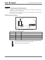
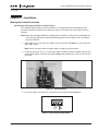
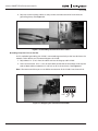
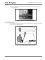
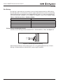
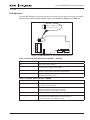
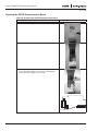
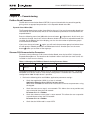
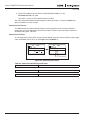
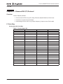
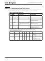
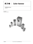
Siemens APOGEE™ FLN (P1) Communication Kit
User Manual
February 2006
Supersedes December 2005
MN04008002E
For more information visit: www.EatonElectrical.com
Siemens APOGEE™ FLN (P1) Communication Kit
February 2006
Important Notice – Please Read
The product discussed in this literature is subject to terms and conditions outlined in Eaton
Electrical Inc. selling policies. The sole source governing the rights and remedies of any
purchaser of this equipment is the relevant Eaton Electrical Inc. selling policy.
NO WARRANTIES, EXPRESS OR IMPLIED, INCLUDING WARRANTIES OF FITNESS FOR A
PARTICULAR PURPOSE OR MERCHANTABILITY, OR WARRANTIES ARISING FROM COURSE
OF DEALING OR USAGE OF TRADE, ARE MADE REGARDING THE INFORMATION,
RECOMMENDATIONS AND DESCRIPTIONS CONTAINED HEREIN. In no event will Eaton
Electrical Inc. be responsible to the purchaser or user in contract, in tort (including
negligence), strict liability or otherwise for any special, indirect, incidental or consequential
damage or loss whatsoever, including but not limited to damage or loss of use of equipment,
plant or power system, cost of capital, loss of power, additional expenses in the use of
existing power facilities, or claims against the purchaser or user by its customers resulting
from the use of the information, recommendations and descriptions contained herein.
The information contained in this manual is subject to change without notice.
Cover Photo: Cutler-Hammer® HVX9000 Drives
MN04008002E
For more information visit: www.EatonElectrical.com
i
Siemens APOGEE™ FLN (P1) Communication Kit
February 2006
Table of Contents
LIST OF FIGURES . . . . . . . . . . . . . . . . . . . . . . . . . . . . . . . . . . . . . . . . . . . . . . . . . . . . . . .
LIST OF TABLES . . . . . . . . . . . . . . . . . . . . . . . . . . . . . . . . . . . . . . . . . . . . . . . . . . . . . . . .
SAFETY . . . . . . . . . . . . . . . . . . . . . . . . . . . . . . . . . . . . . . . . . . . . . . . . . . . . . . . . . . . . . . .
Definitions and Symbols . . . . . . . . . . . . . . . . . . . . . . . . . . . . . . . . . . . . . . . . . . . . .
Hazardous High Voltage . . . . . . . . . . . . . . . . . . . . . . . . . . . . . . . . . . . . . . . . . . . . .
iii
iii
iv
iv
iv
CHAPTER 1 — OVERVIEW . . . . . . . . . . . . . . . . . . . . . . . . . . . . . . . . . . . . . . . . . . . . . . . 1-1
Introduction . . . . . . . . . . . . . . . . . . . . . . . . . . . . . . . . . . . . . . . . . . . . . . . . . . . . . . . 1-1
Specifications . . . . . . . . . . . . . . . . . . . . . . . . . . . . . . . . . . . . . . . . . . . . . . . . . . . . . . 1-1
CHAPTER 2 — BOARD LAYOUT AND CONNECTIONS . . . . . . . . . . . . . . . . . . . . . . . . 2-1
OPTCB Communication Board . . . . . . . . . . . . . . . . . . . . . . . . . . . . . . . . . . . . . . . . 2-1
CHAPTER 3 — INSTALLATION . . . . . . . . . . . . . . . . . . . . . . . . . . . . . . . . . . . . . . . . . . . .
Making the Ground Connection . . . . . . . . . . . . . . . . . . . . . . . . . . . . . . . . . . . . . . .
Bus Terminal Resistors . . . . . . . . . . . . . . . . . . . . . . . . . . . . . . . . . . . . . . . . . . . . . .
Bus Biasing . . . . . . . . . . . . . . . . . . . . . . . . . . . . . . . . . . . . . . . . . . . . . . . . . . . . . . . .
LED Indications. . . . . . . . . . . . . . . . . . . . . . . . . . . . . . . . . . . . . . . . . . . . . . . . . . . . .
Installing the OPTCB Communication Board. . . . . . . . . . . . . . . . . . . . . . . . . . . . .
3-1
3-1
3-3
3-4
3-5
3-6
CHAPTER 4 — COMMISSIONING . . . . . . . . . . . . . . . . . . . . . . . . . . . . . . . . . . . . . . . . . . 4-1
Fieldbus Board Parameters . . . . . . . . . . . . . . . . . . . . . . . . . . . . . . . . . . . . . . . . . . . 4-1
Siemens FLN Communication Parameters . . . . . . . . . . . . . . . . . . . . . . . . . . . . . . 4-1
CHAPTER 5 — SIEMENS FLN (P1) PROTOCOL . . . . . . . . . . . . . . . . . . . . . . . . . . . . . . . 5-1
Overview . . . . . . . . . . . . . . . . . . . . . . . . . . . . . . . . . . . . . . . . . . . . . . . . . . . . . . . . . . 5-1
P1 Point Map. . . . . . . . . . . . . . . . . . . . . . . . . . . . . . . . . . . . . . . . . . . . . . . . . . . . . . . 5-1
CHAPTER 6 — COMMUNICATION BOARD FAULT TRACKING . . . . . . . . . . . . . . . . . . 6-1
ii
For more information visit: www.EatonElectrical.com
MN04008002E
Siemens APOGEE™ FLN (P1) Communication Kit
February 2006
List of Figures
Figure 2-1: OPTCB Communication Board . . . . . . . . . . . . . . . . . . . . . . . . . . . . . . .
Figure 3-1: Cable Stripping . . . . . . . . . . . . . . . . . . . . . . . . . . . . . . . . . . . . . . . . . . .
Figure 3-2: Inserting the Data Cables . . . . . . . . . . . . . . . . . . . . . . . . . . . . . . . . . . .
Figure 3-3: Grounding the Communication Cables . . . . . . . . . . . . . . . . . . . . . . . .
Figure 3-4: Stripping the Communication Cables . . . . . . . . . . . . . . . . . . . . . . . . .
Figure 3-5: Grounding the Communication Cables . . . . . . . . . . . . . . . . . . . . . . . .
Figure 3-6: Using Jumper X4 to Set the Bus Termination . . . . . . . . . . . . . . . . . .
Figure 3-7: Connecting Resistor Biasing . . . . . . . . . . . . . . . . . . . . . . . . . . . . . . . . .
Figure 3-8: LED Indications on the Communication Board . . . . . . . . . . . . . . . . . .
Figure 4-1: Communication Status . . . . . . . . . . . . . . . . . . . . . . . . . . . . . . . . . . . . .
2-1
3-1
3-1
3-2
3-2
3-3
3-3
3-4
3-5
4-2
Table 1-1: Specifications . . . . . . . . . . . . . . . . . . . . . . . . . . . . . . . . . . . . . . . . . . . . .
Table 2-1: OPTCB Bus Connector Signals . . . . . . . . . . . . . . . . . . . . . . . . . . . . . . . .
Table 3-1: Bias Resistor Size vs. Number of Nodes . . . . . . . . . . . . . . . . . . . . . . . .
Table 3-2: Communication Board Status LED (BS) — YELLOW . . . . . . . . . . . . . .
Table 3-3: Fieldbus Status LED (FS) — GREEN . . . . . . . . . . . . . . . . . . . . . . . . . . .
Table 3-4: Installing the OPTCB Communication Board . . . . . . . . . . . . . . . . . . . .
Table 4-1: Changing the FLN Board Commissioning Parameter Values . . . . . . .
Table 4-2: Communication Message Indications . . . . . . . . . . . . . . . . . . . . . . . . . .
Table 5-1: Analog Inputs (AI) . . . . . . . . . . . . . . . . . . . . . . . . . . . . . . . . . . . . . . . . . .
Table 5-2: Analog Outputs (AO) . . . . . . . . . . . . . . . . . . . . . . . . . . . . . . . . . . . . . . . .
Table 5-3: Binary Inputs (BI) . . . . . . . . . . . . . . . . . . . . . . . . . . . . . . . . . . . . . . . . . . .
Table 5-4: Binary Outputs (BO) . . . . . . . . . . . . . . . . . . . . . . . . . . . . . . . . . . . . . . . .
Table 6-1: Communication Board Faults . . . . . . . . . . . . . . . . . . . . . . . . . . . . . . . . .
Table 6-2: AFD Response to Faults . . . . . . . . . . . . . . . . . . . . . . . . . . . . . . . . . . . . .
1-1
2-1
3-4
3-5
3-5
3-6
4-1
4-2
5-1
5-2
5-2
5-3
6-1
6-1
List of Tables
MN04008002E
For more information visit: www.EatonElectrical.com
iii
Siemens APOGEE™ FLN (P1) Communication Kit
February 2006
Safety
Definitions and Symbols
WARNING
This symbol indicates high voltage. It calls your attention to items
or operations that could be dangerous to you and other persons
operating this equipment. Read the message and follow the
instructions carefully.
This symbol is the “Safety Alert Symbol.” It occurs with either of
two signal words: CAUTION or WARNING, as described below.
WARNING
Indicates a potentially hazardous situation which, if not avoided,
can result in serious injury or death.
CAUTION
Indicates a potentially hazardous situation which, if not avoided,
can result in minor to moderate injury, or serious damage to the
product. The situation described in the CAUTION may, if not
avoided, lead to serious results. Important safety measures are
described in CAUTION (as well as WARNING).
Hazardous High Voltage
WARNING
Motor control equipment and electronic controllers are connected
to hazardous line voltages. When servicing drives and electronic
controllers, there may be exposed components with housings or
protrusions at or above line potential. Extreme care should be taken
to protect against shock.
Stand on an insulating pad and make it a habit to use only one
hand when checking components. Always work with another
person in case an emergency occurs. Disconnect power before
checking controllers or performing maintenance. Be sure
equipment is properly grounded. Wear safety glasses whenever
working on electronic controllers or rotating machinery.
iv
For more information visit: www.EatonElectrical.com
MN04008002E
Siemens APOGEE™ FLN (P1) Communication Kit
February 2006
Chapter 1 — Overview
Introduction
The Cutler-Hammer® HVX9000 from Eaton’s electrical business can be controlled, monitored
and programmed from a host system via the Siemens APOGEE™ FLN (P1) communication
protocols with the addition of the OPTCB RS-485 Communication Option Board kit.
If you purchase your Communication Board Kit separate from the drive, please note that it
must be installed in slot E on the control board of the HVX9000.
Specifications
Table 1-1: Specifications
Item
Specification
Communication Board Connections
Interface
OPTCB: Pluggable connector (5.08 mm)
Data Transfer Method
RS-485, half-duplex
Transfer Cable
Twisted pair (1 pair and shield)
Electrical Isolation
500V DC
Communications
Siemens P1
As described in Siemens P1 Protocol Specification
Baud Rate
4800 baud
Addresses
0 to 99
Environment
Ambient Operating Temperature
14 to 131°F (-10 to 55°C)
Storage Temperature
-40 to 140°F (-40 to 60°C)
Humidity
<95%, non-condensing
Altitude
Max. 3280 ft. (1000m)
Vibration
0.5G at 9 to 200 Hz
Safety
MN04008002E
Standards
Fulfils EN 50178 standard
Certification
CE, UL
For more information visit: www.EatonElectrical.com
1-1
Siemens APOGEE™ FLN (P1) Communication Kit
February 2006
1-2
For more information visit: www.EatonElectrical.com
MN04008002E
Siemens APOGEE™ FLN (P1) Communication Kit
February 2006
Chapter 2 — Board Layout and Connections
The RS-485 Communication Board is connected to the communications bus through a 5-pin
pluggable bus connector (OPTCB board).
Communication with the control board of the drive takes place through the standard interface
board connector shown in Figure 2-1.
OPTCB Communication Board
1
2
3
4
X4
5
X1
Bus
Connector
Jumpers
Interface Board
Connector
Figure 2-1: OPTCB Communication Board
Table 2-1: OPTCB Bus Connector Signals
Signal
Connector
Description
NC 1
No connection
VP
2
Supply voltage – plus (5V)
RxD/TxD –N
3
Receive/Transmit data – minus (A)
RxD/TxD –P
4
Receive/Transmit data – plus (B)
DGND
5
Data ground (reference potential for VP)
This pin (1) can be used to bypass the cable shield to the next slave.
Jumper X4 is the 120Ω termination resistor. Set jumper X4 to ON only if the
Cutler-Hammer drive is the last device on the network.
ON
Jumper X1 has no effect on OPTCB board.
OFF
MN04008002E
For more information visit: www.EatonElectrical.com
2-1
Siemens APOGEE™ FLN (P1) Communication Kit
February 2006
2-2
For more information visit: www.EatonElectrical.com
MN04008002E
Siemens APOGEE™ FLN (P1) Communication Kit
February 2006
Chapter 3 — Installation
Making the Ground Connection
Grounding by Clamping the Cable to the Drive Frame
This method of grounding is the most effective, and especially recommended when the
distances between the devices are relatively short or if the device is the last device on the
network.
Note: Normally, the option board has already been installed in slot E of the control board. It is
not necessary to detach the whole board to ground the bus cable shield. Just detach
the terminal block.
1. Strip about 2 in. (5 cm) from the cables (shown at the left of Figure 3-1), and cut off the
gray cable shield.
Note: Do this for both communication cables, except for the last device.
2. Leave no more than 1/4 in. (1 cm) of each cable outside the terminal block, and strip the
ends of both cables (shown at the right of Figure 3-1) to about 0.2 in (0.5 cm) to fit in the
terminals.
Figure 3-1: Cable Stripping
3. Insert the cables into Terminals 3 (Cable A) and 4 (Cable B). See Figure 3-2.
2
1
A
3
4
5
B
Figure 3-2: Inserting the Data Cables
MN04008002E
For more information visit: www.EatonElectrical.com
3-1
Siemens APOGEE™ FLN (P1) Communication Kit
February 2006
4. Strip the communication cables so they can be secured to the drive frame with the
grounding clamp. See Figure 3-3.
Figure 3-3: Grounding the Communication Cables
Grounding Only One Point on the Net
In this method of grounding, the shield is connected to ground only at the last device on the
network. Other devices on the network bypass the shield.
1. Strip about 2 in. (5 cm) from the cables and cut off the gray cable shield.
2. Leave no more than 1/4 in. (1 cm) of each cable outside the terminal block, and strip the
ends of both cables to about 0.2 in. (0.5 cm) to fit in the terminals. See Figure 3-4.
Note: We recommend that you use an Abico connector to fit the shields into the terminal.
2
1
3
4
5
Shield
A
B
Figure 3-4: Stripping the Communication Cables
3-2
For more information visit: www.EatonElectrical.com
MN04008002E
Siemens APOGEE™ FLN (P1) Communication Kit
February 2006
3. Secure the communication cables to the drive frame with the grounding clamp as
shown in Figure 3-5.
Figure 3-5: Grounding the Communication Cables
Bus Terminal Resistors
If the OPTCB connector is the last device on the network, the bus termination must be set to
ON with Jumper X4. See Figure 3-6.
ON = Terminated: This is the last device on network.
OFF = Not Terminated: At least one other network
device is connected past this device.
1
2
3
4
X4
5
X1
Bus
Connector
Jumpers
Interface Board
Connector
Figure 3-6: Using Jumper X4 to Set the Bus Termination
MN04008002E
For more information visit: www.EatonElectrical.com
3-3
Siemens APOGEE™ FLN (P1) Communication Kit
February 2006
Bus Biasing
Bus biasing is required to ensure faultless communication between devices at RS-485 bus.
Bus biasing makes sure that the bus state has proper potential when no one is transmitting.
Without biasing faulty messages can be detected when the bus is in idle state. RS-485 bus
state should be from +0.200 to +7V or -0.200 to -7V. Illegal bus state is from -0.200 to 0.200V.
Table 3-1: Bias Resistor Size vs. Number of Nodes
Number of Nodes
Bias Resistance
2–5
5 – 10
11 – 20
21 – 30
31 – 40
1.8k ohm
2.7k ohm
12k ohm
18k ohm
27k ohm
Failsafe Biasing in OPTCB Option Board
Connect resistor biasing resistors between PIN 2 – PIN 4 and PIN 3 – PIN 5. See Figure 3-7.
Data Data +
Figure 3-7: Connecting Resistor Biasing
National Semiconductor (www.national.com) has a very good application note, Failsafe
Biasing of Differential Buses (AN-847.PDF), concerning this problem.
3-4
For more information visit: www.EatonElectrical.com
MN04008002E
Siemens APOGEE™ FLN (P1) Communication Kit
February 2006
LED Indications
The two LED indicators next to the connector show the present status of the Communication
Board (yellow) and the Fieldbus Module (green). See Figure 3-8, Table 3-2 and Table 3-3.
Yellow = RS-485 Board Status
Green = Fieldbus Status
Yellow
Green
1
2
3
4
X6
5
X1
Figure 3-8: LED Indications on the Communication Board
Table 3-2: Communication Board Status LED (BS) — YELLOW
LED is:
Meaning:
OFF
Option board not activated
ON
Option board in initialization state waiting for activation command from
the Adjustable Frequency Drive (AFD)
Blinking fast (once/sec)
Option board is activated and in RUN state
Option board is ready for external communication
Blinking slow (once/5 secs)
Option board is activated and in FAULT state
Internal fault of option board
Table 3-3: Fieldbus Status LED (FS) — GREEN
MN04008002E
LED is:
Meaning:
OFF
Fieldbus module is waiting for parameters from the AFD
No external communication
ON
Fieldbus module is activated
Parameters received and module activated
Module is waiting for messages from the bus
Blinking fast (once/sec)
Module is activated and receiving messages from the bus
Blinking slow (once/5 secs)
Module is in FAULT state
No messages from Master within the watchdog time
Bus broken, cable loose or Master off-line
For more information visit: www.EatonElectrical.com
3-5
Siemens APOGEE™ FLN (P1) Communication Kit
February 2006
Installing the OPTCB Communication Board
Table 3-4: Installing the OPTCB Communication Board
Procedure
Illustration
1. Remove the cable cover.
2. Open the cover of the control unit.
3. Install the OPTCB option board in slot E on the control
board of the AFD. Make sure that the grounding plate
(shown below) fits tightly in the clamp.
1
2
3
4
5
X4
X1
Grounding Plate
3-6
For more information visit: www.EatonElectrical.com
MN04008002E
Siemens APOGEE™ FLN (P1) Communication Kit
February 2006
Table 3-4: Installing the OPTCB Communication Board, continued
Procedure
Illustration
4. Make a sufficiently wide opening for your cable by cutting
the cover grid as wide as necessary.
5. Close the cover of the control unit and the cable cover.
MN04008002E
For more information visit: www.EatonElectrical.com
3-7
Siemens APOGEE™ FLN (P1) Communication Kit
February 2006
3-8
For more information visit: www.EatonElectrical.com
MN04008002E
Siemens APOGEE™ FLN (P1) Communication Kit
February 2006
Chapter 4 — Commissioning
Fieldbus Board Parameters
The RS-485 Communication Board (OPTCB) is commissioned with the control keypad by
giving values to appropriate parameters in the Expander board menu M4.
Expander Board Menu (M4)
The Expander board menu makes it possible for the user (1) to see what expander boards are
connected to the control board, and (2) to view and edit the parameters associated with the
expander board.
Enter the following menu level (G4) with the menu button
(right arrow). At this level, you
can browse through slots A to E with the Browser buttons to see which expander boards are
installed. On the bottom line of the display, you also see the number of parameter groups
associated with the board.
If you press the menu button
again, you will reach the parameter group level where there
are two groups: Editable parameters and Monitored values. Another press on the menu
button
takes you to either of these groups.
Siemens FLN Communication Parameters
To commission the Siemens FLN Communication Board, enter the level P4.5.1.# from the
Expander Board Menu 4. The board can be installed in either slot D (G4.4) or slot E (G4.5). It is
installed in slot E from the factory.
Table 4-1: Changing the FLN Board Commissioning Parameter Values
#
Name
Default
Range
Description
1
Communication
Timeout
10
0 – OFF
1 – 300 s
See Communication Timeout on Page 4-2.
The SLAVE ADDRESS of every device must be set before connecting to the bus. The SLAVE
ADDRESS must be the same as in the master configuration. The baud rate is automatically
configured for 4800. No adjustment is possible.
1. Review the following drive and fieldbus application parameter settings:
MN04008002E
●
Check that application HVX9.11 or later is selected.
Application Selection S3.2 = HVX9.11 or later version
Refer to the HVX9000 User Manual for instructions on how to set parameters using
the keypad.
●
Check that start source auto is set to network. This allows the user to provide start/
stop commands from the FLN network.
Parameter P1.1.17 = Fieldbus
●
Check that reference source auto is set to network. This allows the user to provide
a speed reference from the FLN network.
Parameter P1.1.18 = Fieldbus
●
Check that the HOA mode is set to AUTO.
For more information visit: www.EatonElectrical.com
4-1
Siemens APOGEE™ FLN (P1) Communication Kit
February 2006
2. Set the FLN address for the device if desired (default address is 99).
Parameter P1.13.9 = (1 – 99)
The drive is set up for FLN network communication.
For more information about the description of some parameters, see the HVX9000 User
Manual, HVX9.11 or later version.
Communication Timeout
The RS-485 Communication Board initiates a communication error if communication is
broken for as long as defined by the Communication Timeout. Communication Timeout is
disabled when given a 0 value.
Communication Status
To see the present status of the communication board, enter the Communication status page
from the Monitor menu (G7.5.2). See Figure 4-1 and Table 4-2.
Comm. status
Monitor
V1
V1
0.841
Good Message
Error Message
Figure 4-1: Communication Status
Table 4-2: Communication Message Indications
Messages
Indications
Good messages
0 – 999
Number of messages received without communication errors
Error messages
0 – 64
4-2
Number of messages received with CRC or parity errors
For more information visit: www.EatonElectrical.com
MN04008002E
Siemens APOGEE™ FLN (P1) Communication Kit
February 2006
Chapter 5 — Siemens FLN (P1) Protocol
Overview
The P1 Protocol provides:
●
Direct control of Drive (e.g. Run, Stop, Direction, Speed reference, Fault reset)
●
Full access to necessary parameters
●
Monitoring of Drive status (e.g. Output frequency, Output current, Fault code)
P1 Point Map
Analog Input (AI) Point Map
Table 5-1: Analog Inputs (AI)
MN04008002E
NPT
Point Number
Description
Units
AI
3
FREQ OUTPUT
Hz
AI
4
PCT OUTPUT
%
AI
5
SPEED
rpm
AI
6
CURRENT
A
AI
7
TORQUE
%
AI
8
POWER
%
AI
9
DRIVE TEMP
° F (° C)
AI
10
DRIVE KWH
kWh
AI
11
DRIVE MWH
MWh
AI
12
RUN TIME
Hours
AI
13
DC BUS VOLT
V
AI
14
MOTOR VOLT
V
AI
43
DRV ACT AO 1
mA
AI
45
DRV ACT AI 1
V
AI
46
DRV ACT AI 2
mA
AI
60
PID FEEDBACK
%
AI
65
PID ERROR
%
AI
70
DIN STATUS
—
AI
71
RO STATUS
—
AI
90
LAST FAULT
—
AI
91
PREV FAULT
—
For more information visit: www.EatonElectrical.com
5-1
Siemens APOGEE™ FLN (P1) Communication Kit
February 2006
Analog Output (AO) Point Map
Table 5-2: Analog Outputs (AO)
NPT
Point Number
Description
Units
AO
1
CTLR ADDRESS
—
AO
2
APPLICATION
—
AO
20
OVRD TIME
Hours
AO
30
CURRENT LIM
%
AO
31
ACCEL TIME 1
Seconds
AO
32
DECEL TIME 1
Seconds
AO
48
CMD DRV AO1
%
AO
51
SPEED REF
%
AO
52
PID SETPOINT
%
AO
61
PID GAIN
%
AO
62
PID I TIME
Seconds
AO
63
PID D TIME
Seconds
AO
99
ERROR STATUS
—
Binary Input (BI) Point Map
Table 5-3: Binary Inputs (BI)
5-2
NPT
Point Number
Description
0=
1=
BI
21
FWD / REV
Forward
Reverse
BI
23
STOP / RUN
Stop
Run
BI
25
DRIVE READY
Not Ready
Ready
BI
35
INTERLOCK
Yes
No
BI
49
AT SPEED
No
Yes
BI
81
BYPASS ACT
Off
On
BI
93
OK / FAULT
OK
Fault
For more information visit: www.EatonElectrical.com
MN04008002E
Siemens APOGEE™ FLN (P1) Communication Kit
February 2006
Binary Output (BO) Point Map
Table 5-4: Binary Outputs (BO)
MN04008002E
NPT
Point Number
Description
0=
1=
BO
18
RST KWH-MWH
No
Reset
BO
19
RST Run Time
No
Reset
BO
22
CMD FWD / REV
Forward
Reverse
BO
24
CMD STP / STRT
Stop
Start
BO
29
DAY / NIGHT
Day
Night
BO
33
LOCK PANEL
Open
Lock
BO
36
CMD DIN 3
Off
On
BO
37
CMD DIN 4
Off
On
BO
38
CMD DIN 5
Off
On
BO
39
CMD DIN 6
Off
On
BO
40
CMD DRV RO 1
Off
On
BO
41
CMD DRV RO 2
Off
On
BO
42
CMD DRV DO 1
Off
On
BO
80
CMD BYPASS
Disable
Enable
BO
94
RESET FAULT
No
Reset
For more information visit: www.EatonElectrical.com
5-3
Siemens APOGEE™ FLN (P1) Communication Kit
February 2006
5-4
For more information visit: www.EatonElectrical.com
MN04008002E
Siemens APOGEE™ FLN (P1) Communication Kit
February 2006
Chapter 6 — Communication Board Fault Tracking
The table below presents the faults related to the Siemens FLN (P1) option board. For more
fault code information, see also HVX9000 User Manual, Fault Tracking Section.
Table 6-1: Communication Board Faults
Fault
Code
Fault
Possible cause
Possible solutions
37
Device change
Option board changed
Reset
38
Device added
Option board added
Reset
39
Device removed
Option board removed
Reset
40
Device unknown
Unknown option board
Check the installation.
If installation is correct contact the
nearest Eaton distributor.
53
Communication
bus fault
The data connection between the
Check the installation.
communication bus master and the If installation is correct contact the
communication bus board has
nearest Eaton distributor.
failed.
54
Slot fault
Defective option board or slot
Check that the board is properly
installed and seated in slot. If
installation is correct, contact the
nearest Eaton distributor.
You can define with parameters how the AFD shall react to certain faults:
Table 6-2: AFD Response to Faults
MN04008002E
Code
Parameter
Min.
Max
P1.7.22
Response to
fieldbus fault
0
P1.7.23
Response to slot 0
fault
Unit
Step
Default
Note
3
1
2
0=No response
1=Warning
2=Fault, stop acc. to 2.4.7
3=Fault, stop by coasting
3
1
2
0=No response
1=Warning
2=Fault, stop acc. to 2.4.7
3=Fault, stop by coasting
For more information visit: www.EatonElectrical.com
6-1
Siemens APOGEE™ FLN (P1) Communication Kit
February 2006
6-2
For more information visit: www.EatonElectrical.com
MN04008002E
Company Information
Eaton’s electrical business is a global leader in electrical control, power distribution, and
industrial automation products and services. Through advanced product development,
world-class manufacturing methods, and global engineering services and support,
Eaton’s electrical business provides customer-driven solutions under brand names such
as Cutler-Hammer®, Powerware®, Durant®, Heinemann®, Holec® and MEM®, which
globally serve the changing needs of the industrial, utility, light commercial, residential,
and OEM markets. For more information, visit www.EatonElectrical.com.
Eaton Corporation is a diversified industrial manufacturer with 2004 sales of $9.8 billion.
Eaton is a global leader in fluid power systems and services for industrial, mobile and
aircraft equipment; electrical systems and components for power quality, distribution and
control; automotive engine air management systems, powertrain solutions and specialty
controls for performance, fuel economy and safety; and intelligent truck drivetrain systems
for safety and fuel economy. Eaton has 56,000 employees and sells products to customers
in more than 125 countries. For more information, visit www.eaton.com.
Eaton Electrical Inc.
1000 Cherrington Parkway
Moon Township, PA 15108-4312
USA
tel: 1-800-525-2000
www.EatonElectrical.com
© 2006 Eaton Corporation
All Rights Reserved
Printed in USA
Publication No. MN04008002E/CPG
February 2006