1
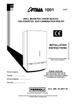
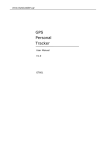
CHAFFOTEAUX LIMITED
BRITONY II FF
G.C. No 52.980.21
This appliance has been tested and certificated by British Gas
For use on natural gas only)
installation and
servicing instructions
(leave these instructions adjacent‘to the gas meter)
GENERAL
1.
The BRITONYII FF is a fanned draught, balanced flued instantaneous multipoint appliance. The flue is suitable for
rear outlet, or to either side. The maximum recommended flue length is 3 m. straight.
The appliance is for connection to a mains cold water supply only.
A permanent electrical connection is required and should be provided by use of a fused spur. The external electrical supply should be via a double pole switch having 3 mm. contact separation in both poles. If the appliance is
installed in a bathroom the fused spur must be external to the bathroom.
When on pilot only the fan runs at ‘low speed’ increasing to normal speed when there is a demand for hot water.
Included are a pressure switch, which operates if the fan stalls or if the flue is obstructed, and a low temperature
sensor which will turn off the fan when the appliance is running on pilot only (fan low speed) in the event of low
air temperatures likely to cause freezing in the appliance.
Guarantee
1.1
The guarantee on this appliance is void if it is not installed in accordance with the recommendations made herein
or in a manner approved by the manufacturer.
I
Dimensions
1.2
-
A
B
C
D
E
F
G
H
J
K
1
M
N
P
S
T
v
W
X
mm
ins.
658
395
270
100
40
385
438
778
728
53
55
98
70
285
105
199
290
90
868
25.9
15.5
10.6
4.0
1.6
15.15
17.25
30.6
28.6
2.1
2.15
3.8
2.75
11.22
4.13
7.8
11.4
3.54
34.14
X
-
-
2
Technical Data
1.3
Heat input nominal
.
Heat output nominal . . . . . . . . . .
Gas rate (maximum)
. . . . .
Burner pressure . . . . . . . . . . . . . . . . . . . .
Burner pressure tolerance
.
Main burner injectors .
. . ..
Pilot injectors
.. .. ...........
Water flow rate - raised 50 ‘C (90 ‘F) .
Water flow rate - raised 30 “C (54 “F) .
Minimum operating head
.........
Maximum operating head .
.... . .
Electrical Connections - 240 V
50 Hz
supply fused 3 A.
.
..
.
..
..
..
..
.
.
..
..
.
28.6 kW
22.4 kW
2.67 ms/h
10.9 mbar
2 1.Ombar
1.23 mm (stamped 1.23)
0.23 mm (stamped 231
6.3 I/min
10.9 I/min
7.5 m.
100 m.
97583 Btu/h
76000 Btu/h
94.3 ft3/h
4.4 in.w.g.
2 0.4 in.w.g.
1.4 gpm
2.4 gpm
25 ft ( 10 psi)
328 ft (I 50 psi)
The minimum water pressure is for the correct operation of the appliance only. An additional allowance must be
made for the resistance of pipework and fittings particularly where showers and washing machines are used.
This should be equivalent to 2 m. (6.5 ft) head.
..
.
. ..
..
.
..
..
..
..
..
..
..
Water inlet (Compression tYpe fittings) . .
Water outlet (Compression type fittings)
Gas (Compression type fittings)
.
Height (including flue bend) .
...
Width
. ...........................
Depth . . . . . . . . . . . . . . . . . . . . . . . . . . . .
Weight..............................
Space for fixing - top (above flue)
- bottom (below case)
- sides
.............
- front .
.
.
Hole for the air inlet duct
. .
.
15 mm Copper
Right hand connection
15 mm Copper
Left hand connection
15 mm Copper
Centre connection
778 mm (30.6 in)
395 mm (15.5 in)
270 mm (IO.6 in)
20 kg. (42 lb)
50 mm ( 2 in)
178 mm ( 7 in)
25 mm ( 1 in)
600 mm (24 in)
107 mm ( 4 in) 0 (diameter)
The BRITONYII FF is supplied in one carton.
L
1.4
Flue Length
Minimum Wall Thickness 3 in (75 mm)
RearOutlet
Wallthickness
Upto 612.5mm
mm
Over612.5
Delivered
with
appliance
Extension
available
Flue duct length = wall thickness + 25 mm
Air inlet duct length = wall thickness + 25 mm
SideOutlet
EM= Wallthickness
DM = Distance
fromwailto
Rue
Air inlet duct length EM + DM + 130 mm
ptN”61061
I
2.
INSTALLATION REQUIREMENTS
The appliance must be installed so that the flue terminal
is exposed to external air. The appliance must NOT be installed so that the terminal discharges into another room
or space such as an outhouse or lean-to. It is important
that the position of the terminal allows a free passage of
air across it all times. The minimum acceptable spacings
from the terminal to obstructions and ventilation openings are specified in the following chart.
2.1 Related Documents
The installation of the heater must be in accordance with
the relevant requirements of the Gas Safety (Installation
and Use) Regulations 1984, Building Regulations, the current IEE Wiring Regulations and the Byelaws of the local
water undertaking. It should also be in accordance with
any relevant requirements in British Standard Codes of
Practice. Detailed recommendations are contained in the
following British Standard Codes of Practice :
CP 331 : Pt. 3 : 1974.. BS 5546 : 1979, BS 5440 : Pt. 1 :
1978 and BS 5440 : Pt. 2 : 1976.
I I
1.
2.2 Location
2.
The location chosen for the appliance must permit the
provision of a satisfactory flue termination. The location
must also permit adequate space for servicing and air circulation around the appliance.
The appliance may be installed in any room or internal
space although particular attention is drawn to the requirements of the IEE Wiring Regulations and, in Scotland,
the electrical provisions of the Building Standards applicable in Scotland, with respect to the installation of a heater
in a room or internal space containing a bath or shower.
Where a room sealed appliance is installed in a room
containing a bath or shower, any electrical switch or appliance control, utilising mains electricity should be so situated that it cannot be touched by a person using the
bath or shower.
Where the installation of the appliance will be in an
unusual location special procedures may be necessary
and BS 5546 gives detailed guidance on this aspect.
A compartment used to enclose the appliance must be
designed and constructed specifically for this purpose. An
existing cupboard or compartment may be used provided
that it is modified for the purpose.
Details of essential features of cupboard/compartment
design are given in BS 5546.
13.
Diily belowanopenable
window,air vent
or anyotherventilation
opening.
II
1Belowqutterinq,
drainpipesor soilpipes.
1
75mm(3iIL)
or eaves.
I Belowbalconies
1
2OOmm(8
ill.) 1
4.
Aboveadjacent
groundor balconylevel
5.
Fromverticaldrainpipesor soilpipes.
16.
7.
8.
300mm(12in.)
I
1Fromintemalor externalcomers.
I
3OOmm(12in.)
7.5mm(3 in.)
1
3OOmm(12in)1
Froma surface
facingtheterminal
600mm(24in)
Froma terminalfacingtheterminal
1200mm(46h.)
Note -Where the terminal is fitted within 850 mm (34 in.)
of a plastic or painted gutter or 450 mm (18 in.) of painted eaves an aluminium shield of at least 750 mm (30 in.)
long should be fitted to the underside of the gutter or
painted surface.
Where the lowest part of the terminal is less than 2 m.
(6.5 ft) above the level of any ground, balcony, flat roof
or place to which any person has access and which adjoins
the wall in which the terminal is situated must be protected by a guard of durable material (a terminal guard is
available from Chaffoteaux Limited) or from Quinnell Barrett & Quinnell. 01.639.1357. (GC No 381.782)
The air inlet/products outlet duct and the terminal of the
appliance must not be closer than 25 mm (I in.) to any
combustible material. Detailed recommendations on the
protection of combustible material are given in BS 5440
Pt. 1 : 1978 (Sub-clause 20.1).
2.3 Gas Supply
An adequate sized gas meter must be connected to the
service pipe. Where necessary the local Gas Region of British Gas will arrange for the existing meter to be checked
or for a suitable meter to be installed. On no account
must any work be carried out on the gas meter other
than by the local Gas Region or their specifically authorised contractor.
Installation pipes should be fitted in accordance with CP
331 : 3. Pipework from the meter must be of adequate
size. Pipes of a smaller size than the gas connection
should not be used.
The complete installation must be tested for gas soundness and purged in accordance with CP 331 : 3.
IMPORTANT NOTICE: TIMBER FRAMED HOUSES.If the
appliance is to be fitted in a timber framed building it
should be fitted in accordance with the British Gas publication “Guide for Gas Installations in Timber Framed Housing” reference DM2. If in doubt advice must be sought
from the local Gas Region of British Gas.
2.5 Wall Mounting
The appliance should be installed on a flat noncombustible material which will not reverberate. What
ever the thickness of the wall a hole 100 mm (4 in.) in diameter will be required for the app!iance flue assembly. It
is recommended that a core drill be used to form this
hole.
For dimensions and clearances see sections 1.2 and 1.3.
2.4 Siting the Flue Terminal
The flue must be installed in accordance with BS 5440 : Pt.
1.1978. The flue is suitable for STRAIGHTflue application
only.
The following notes are intented to give general guidance.
The standard flue set is suitable for walls having a thickness of 75 mm (3 in.) to 612.5 mm (24 in.) for rear outlet
fluing or up to 500 mm (19,5 in.) for side outlet fluing.
Other flue options are available to a maximum of 3 m (9
ft. 8 in.) to special order.
2.6 Flue Terminal Assembly
The flue may be fitted from inside or outside of the building. If fitting from inside the flue duct should be assembled into the air inlet duct and the assembly passed trough
the hole in the wall. The outside diameter of the terminal is
the same as outside diameter of the air inlet duct.
4
2.7 Air supply
The cable should be passed through the gland on the top
of the appliance and the clamp tightened to secure the
cable. Ensure current carrying conductors become taught
before earthing conductor should cable slip from the
cord anchorage. Connection to the appliance should be
made in accordance with diagram (see section 3,6,2).
The appliance does not require any purpose provided
ventilation unless installed in a compartment. A compartment enclosing an appliance requires high and low level
openings. These openings must either communicate with
a room or internal space or be direct to outside air. The
minimum FREEarea of the opening must be :
Highlevel
2.9 Description of Operation
Lowlevel
Air from mom or internalspace 258cm2(40in2)
Air directfromoutside
129cm2(20in.2)
Read in conjunction with figs 1. 2 and 4).
258cm*(40irL2)
129ails (20in*)
The controls on the BRITONYII FF are comprised of a range of thermal, electric and electronic switches. Broadly, the
thermal controls are for the pilot flame supervision, the
electrical controls are functional switching and the electronic controls act as a security for the functional controls.
The circuit is designed so that, under normal conditions,
the fan runs continuously at low speed and automatically
changes to high speed when the gas valve opens. If,
however, the incoming air temperature approaches 0 “C
the integral frost protection thermostat interrupts the
low fan speed signal. Under this condition, if there is a demand for hot water, then the fan recommences at.high
speed. There is an in-built delay circuit to prevent the
safety devices operating prematurely.
The pilot can only be established under the control of the
thermocouple flame failure circuit after the mains electricity connection is made since it is dependent upon the
energising of relay-RLI.
If the air flow is not proved on high speed the flame failure
device will operate by interrupting the thermocouple as a
result of the failure of the circuit through relay-RLI.
Additional security is provided for the condition where,
because the linkage is mechanical, the main gas burner is
initiated but the microswitch has remained in the low fan
speed position. If the burner is sensed in the low fan
speed circuit the appliance fails safe.
2.8 Electrical Connections
The appliances must be earthed.
The installation should be undertaken by a competent
electrician and should be in accordance with the current
edition of the IEEWiring Regulations.
Particular attention should be paid to cross bonding.
The appliance must be provided with a means of isolation.
If installed in a bathroom the means of isolation must be
external to the bathroom or a double pole cord switch fitted.
Acceptable methods of connection are :
1. A switched, double pole fused spur with 3 mm contact
separation on all poles.
2. A double pole switch where the supply must be suitably fused 3 A.
3. An un-switched socket outlet compling with BS 1363.
The method of connecting the plug brown wire to live (U
blue wire to neutral (N) and green/yellow to earth ( ),
see fig. 3.
A three core cable should be used and a heat resisting cable of 0.75 mm2 (24 x 0.2 mm) is considered suitable.
ELECTRIC
FUNCTIONAL FLOW DIAGRAM
SUPPLY
.
L
THERMOSTAT
’
FAN
r
1r
17
L
r
AA
I
I
MICRO SWITCH
SAS VALVE
-
I
RELAY
RL2
i
7
RELAY
RLl
L
r
’
THERM0
COUPLE
THERM0
-t
ELECTR’C
VALVE
CIRCUITDIAGRAM
L
2A
Fig. 1
*
WIRING DIAGRAM
ELECTRICAL
CONNECTION
fuse 3 A
FU Fura
IE
(2 A)
lonkatlon
electrode
TC Themlocouplr
BM Themm4@ctt’lc
switched
PR Pressure
Br
Brown
BI
Blue
R
Red
W
Whlts
0
onnos
Bk
Black
v
VI&t
0
Grey
P
Plnk
fused
spur
Valve
SW Mlcmswltch
Y-C Yellow
heater
NB : IF APPLIANCE INSTALLED IN A BATHROOM
SPUR MUST BE EXTERNAL TO ROOM
Switch
-Green
---------I---------NB : IF APPLIANCE INSTALLED IN A BATHROOM
SWITCH TO BE OF PULL CORD TYPE
heater
neutral
earth
I
9
1
.
. I
i-.,.-.-i
3 A. fuse way
Fig. 3
Fig. 2
6
!d’i
I
.
*I
i-.-.i
double pole
switch
i
MICRO-SWITCH
WATERFLOW
PREBSURE SWITCH
PRINTED CIRCUIT BOARD
,--w--w-------
11
Fig. 4
3.
INSTALLING THE APPLIANCE
A vertical flat area is required for the appliance : 1006 mm high x 445 mm wide (39.6 in x 17.5 in). The surface on which
the appliance is mounted must be of a non combustible material.
3.1 Packaging
The appliance is attached to the wall via the mounting bracket and two bottom screw fixings. The appliance is packed in a
single carton. Remove contents from carton and check against list.
I) APPLIANCE- Assembled with trims.
21 FLUEASSEMBLY: a)
b)
c)
d)
Air inlet duct complete with terminal.
2nd section flue duct (inside air inlet duct).
Flue turret with 1st section flue duct fitted.
Plastic turret cover.
3) ACCESSORYBOX- containing : -
mounting bracket
gas and water connections with washers, nuts and olives
flue locking ring and ‘0’ ring seal
2 gaskets
4 wall mounting screws
4 turret fixing screws
2 turret cover fixing screws
1 gas control knob
1 temperature selector knob
7
-.
3.2
Preparing and
fitting the appliance
Preparation :
y---
1
142
-
1:
142
j
--c
197.5 mm minimum
I
7.
--rI !I
I i
- Remove the bottom trim by pulling forwards.
- Slide the controls facia plate (PI upwards to disengage from retaining bracket.
- Release the front case by removing the four fixing
screws and washers positioned at the top, bottom
and centre of appliance.
- Remove the front case by lifting off the top locating lugs and pulling forward to clear the water
section at the base of the appliance.
NOTE: A template is not supplied with this appliance.
Particular care is therefore necessary to ensure that
the appliance mounting bracket is fitted level and positioned accurately, relative to the flue.
- Refer to the drawings opposite for rear and side
flue applications and/or to the dimensions given in
Section 1.4, refer also to Section 2.4 for flue terminal siting.
- Set out and rill hole for flue using a 100 mm (4 in)
core drill.
- Using the dimension 290 mm (11.4 in) accurately
mark position for bracket.
- Drill and plug the wall.
- Fix bracket to wail using No. 12 screws provided,
ensuring that the bracket is level. If necessary adjust bracket, finally secure in position.
- Hang the appliance on the bracket, and re-check
for level. Mark bottom fixing holes, remove appliance, drill and plug the wall to suit No. 12 screws.
- Re-hang appliance and secure with screws provided.
-
Fitting the flue
3.3
D
-
-
Gas Connection
3.4
Measure the wall thickness and cut flue duct and
air inlet duct to required length, (see Section 1.4).
Peel off protective paper from adhesive side of
cork gasket (A) and place on mating side of flue
turret(B) lining up screw holes and press down.
Fit locking ring (C) and ‘0’ ring over the air inlet
duct.
Fit flue duct and turret so that it engages into the
terminal.
Engage locking ring over lugs by turning in an anticlockwise direction viewed from behind turret.
Passthe assembled flue through the wall.
If long flue sections are used (up to 3 metres) and
difficulty is found, these can be assembled whilst
being passed through the wall.
Seat the turret onto the top of the appliance ensuring the gaskets are in position.
Secure with 4 screws provided.
Do not fit plastic turret cover or the front case until electrical connections have been made and the
appliance tested for gas and water soundness (see
Section 5.1).
A sealing ring (D) is supplied which can be used to
seal the air inlet duct to wall joint-externally.
Make good inside wall surface.
Fit the gas service cock provided using the fine
filter/washer to seal the connection. Fit the nut and
olive onto the 15 mm gas supply pipe and tighten.
Test the complete gas installation for soundness
’ andpurgeKP:331.3).
c$
I
3.5
Water connections
- Remove the plastic covers protecting the water inlet and the water outlet connections.
- Fit the water service cock provided to the right
hand connection at the bottom of the appliance
using the coarse filter/washer to seal the connection.
- Fit the nuts and olives onto the supply and delivery
pipes.
- Connect the inlet supply to the water service cock
and tighten.
- The water service cock supplied with the appliance
incorporates a drain plug.
- Ensure that all water connections are fully tightened.
9
Electrical connections
3.6
3.6.1. Pressure Switch
- Connect the wires at the top of the appliance to
the pressure switch.
- The grey wire is connected to normally closed (NC
I) contact.
- The pink wire to the normally open (NO 21contact.
- The violet wire to the common (P) contact.
- Fit the flue turret cover passing the wire through
one of the slots provided and secure with the
screws provided.
- See figure.
3.6.2. Mains Connection
- Pass 0.75 mm2 heat resisting cable through cable
gland.
- The earth wire (green yellow) must be connected
to the earth pillar ( & ).
- The live (brown) and neutral (blue) should be
connected as indicated into the terminal block.
- Check that component plugs are pushed home.
- Check for continuity, polarity and earthing.
L
10
10
Do not use the appliance with push on hand showers that
fit over existing hot and cold water taps or with mixer
taps unless both supplies come from the same source.
Showers forming part of bath mixers are not recommended for satisfactory operation of the appliance.
APPLICATIONSOF THE BRITONY II FF
The appliance is designed to serve a varietv of hot water
draw off Points including washing machines and showers.
The appliance can be connected to all hot water draw-off
points in the installation. If more than one outlet is open
simultaneouslv the total flow of water cannot exceed
that quoted in the Technical Data.
The appliance is comptatibie with most current automatic
washing machines but care should be taken to ensure
that the machine is capable of accepting water at the design flow of the appliance. Hot and cold fill machines normally require a hot water temperature of 60 “C (140 ‘F),
the appliance producing approximately 6.5 Vmin
Vl.44gpm) at this temperature. The advice of the washing machine manufacturers should be sought but generally it is only necessary to remove the water flow restrictor (if fitted) in the hot water inlet connection of the machine to obtain a satisfactory appliance operation.
Contact Chaffoteaux Limited for details of those machines known to be compatible with the BRITONYII FF.
4.1 Pipework
The following notes are for general guidance only.
0) The appliance performance may be affected if the
installation has old pipework forming dead-legs or air
reservoirs. Always ensure that any old pipework is either removed or capped off immediately adjacent to
the pipework that will be in use.
(ii) The size of the pipework between the applianceand the
various draw-off points should be sizedto ensure an ade
quate flow at all drawoff points when used indiiually.
(iii) A check should be made of all stop cocks in the incoming supply and it should be ensured that they are of
the fixed jumper pattern. Loose jumpers can be pinned or soldered into position.
.................
..-.*.*::.:::.
._*.-.~.~.~.~_~.~.~
........ ..:::::.
HOT WATER
TO COLD
DEREVE
TAPS
4.2
The appliance can be used to supply hot water to a separate shower draw-off. The appliance should not be used
to supply more than one shower mixing valve. The recommended pipework arrangement for a single shower
head is shown above. Only those fittings detailed should
be used with the appliance. Chaffoteaux Limited do not
supply the water governor or any shower fittings. For local suppliers of these please contact :
Water governor - Dereve (Flow Controls) Limited
Park lane
HANDSWORTH
Birmingham 821 8LE
Tel :021 5537 021
Shower Accessories - Caradon Mira Ltd.
Cromwell Road, CHELTENHAM
Gloucester GL 52 5EP
Tel : 0242 27953
Aqualisa Products Limited
Horton’s Way, London Road,
WESTERHAM,Kent, TN16 IBT
Tel : 0959 63240
11
WATER
ALTERNATIVE
POSITION
A water reservoir is provided on the outlet side of the
heat exchanger to limit the water temperature due to
((after heat )a.
5.
5.
COMMISSIONING
5.1
Putting into Service
5.1.1. Open the gas and water service cocks beneath
the appliance, purge the gas supply (CP331:3). Turn
on an adjacent tap and purge the water side of the
installation.
Test for water soundness at all appliance and external pipework connections.
Switch on electrical supplv, fan will run at low speed.
5.1.3. To light the pilot temporarily fit the gas
control knob (A) and light the pilot by turning the
knob 90’ anti-clockwise. It may be necessary to purge
the pilot gas supply, if so, wait a few minutes, return
the gas control knob to the OFF position and repeat.
(The pilot supply will only purge when the gas control
knob has been turned 90’ anti-clockwide).
5.1.4. When the pilot is lit turn the control knob (A)
fully anti-clockwise as shown in the diagram. Test for
gas soundness using leak detection fluid on all gas
connections.
5.1.5. Check the operation of the flame failure device by blowing out the pilot light, the flow of
gas to the pilot will cease and the thermoelectric valve should drop out with an audible ‘click’ within approximately 30 seconds.
5.1.6. Remove gas control knob (A).
5.1.7. Switch off electrical supply.
5.1.8. Fit front case by locating bottom first and ensuring top of case locates over bracket. Secure with 4
screws and washers previously removed.
- The centre screw and plastic washer retains the
fascia mounting bracket.
- Replace the control fascia plate by sliding down
onto the support bracket.
- Fit bottom trim by sliding onto rails.
- Fit the gas control knob (A) and the temperature
selector knob (B). The temperature selector knob
should be pushed onto the spline until it locates.
Turn fully clockwise to (+I, reposition knob as required, so that indicator dot is opposite the (+) sign.
5.1.9. Switch on electrical supply.
- Light the pilot and turn gas control knob (A) fully
anti-cockwise to, the main gas position.
- If the pilot is now extinguished for any reason return the gas control knob to the OFF position and
wait approximately 30 seconds for the safety interlock to reset before repeating.
12
5.2
Gas Pressure
- Turn on an adjacent hot water draw off, the appliance will now light and the fan will change to high
Speed.
- With the front case fitted, check the burner setting pressure at the pressure test point U.
- If the burner setting pressure is not correct, check
that the pressure at the gas service cock, test
point is 20 mbar (8 in.w.g.) with the appliance operating. If the inlet pressure is not correct, check for
any possible blockage or restriction in the pipework
to the appliance. If the inlet supply pressure cannot
be corrected contact your local gas region. The
heat input to the appliance is preset and nonajustable.
Slow Ignition
5.4
.4
- Check burner ignition which should be smooth and
quiet (not explosive).
- If slow ignition requires adjustment proceed as in
Section 6.1 to remove front case.
- Adjust slow ignition device l/4 turn at a time. Refit
front case and recheck operation.
NOTE : Turning screw A clockwise delays ignition.
Microswitch
The microswitch is factory set and should not require adjustment. When the appliance is at rest the fan runs
continuously at low speed. check operation as follows set temperature selector to +. open draw off. The fan
should now come to high speed before the burner ignites. On closing draw off burner should extinguish before
the fan resumes at low speed. If fan/burner operational sequence is NOT as described consult or contact Chaffoteaux Ltd (Service Department).
5.5
The Pressure Switch
Check the operation of the pressure switch as follows : Open draw off, fan comes to high speed and the burner
ignites. Close draw off, burner extinguishes and when fan resumes at low speed listen for the ‘click’ as the relay
changes over. This should be followed within 15 seconds by a lighter ‘click’ as the pressure switch changes over. If
the time separation is greater than 15 seconds or if the pilot extinguishes it suggests that the pressure switch is
incorrectly set and should be referred to Chaffoteaux Ltd (Sercice Department).
13
5.6
Thermoelectric
Circuit
The Thermocouple Circuit is fitted with an interrupter so that if the air flow is not proved on high speed the circuit is incomplete and the flame failure device will operate. In the case of intermittant pilot failure or permanent
pilot failure the thermocouple circuit can be checked with a British Gas Multimeter or suitable Millivolt Meter to
determine if the pilot failure is due to poor thermocouple output, high resistance through Relay-l contact or
faulty thermoelectric valve. (See Section 2.9 Fig. I).
5.7
Handing Over
Hand the User’ instructions to the user or purchaser and instruct in the correct and safe operation of the appliance.
Explain to the user or purchaser that if the appliance is not used for long periods it is recommended that the appliance is drained, this is particularly important during the winter months (see servicing instructions for procedure to drain appliance).
Finally, advise the user or purchaser that, for continued efficient and safe operation of the appliance it is important that adequate servicing is carried out at regular intervals.
14
14
6.
SERVICING INSTRUCTIONS
Before commencing any service work :
1. Isolate electrical supply.
2. Remove bottom trim by sliding forward.
3. Turn off gas at gas service cock.
4. Turn off water at water service cock.
5. Drain the appliance by opening hot water outlet tap and removing drain plug in the water service cock.
6.1
Front Casing
To remove :
- Pulloff gas control and temperature selector knobs.
- Remove controls facia plate by sliding upwards.
- Remove the four fixing screws which secure the
front case (top, bottom and centre) taking care not
to loose facia retaining bracket and washers.
- Remove the front case by lifting off the to locating
lugs and pulling forward to clear the water section
at the base of the appliance.
6.2
Burner
-
-
6.3
Pilot
Remove the combustion chamber front panel as
detailed below.
Remove two threaded screws which secure the
front panel of the combustion chamber skirt to the
flue hood (A) Section 6.4.
Remove three self-tapping screws on either side of
combustion chamber skirt (B) Section 6.4.
Unscrew the pilot tube clamping screw (A) and remove the clamp and screw and pilot tube. Disconnect the pressure test point tube from the left
hand end of the manifold.
Remove the burner manifold by unscrewing the
two screws (B) and two screws and washers (0.
Unplug ionisation electrode at the connector.
Withdraw the burner head assembly taking care
not to damage the pilot bvurner/electrode assembly or the ignition leads.
The burner head should be turned upside down
and cleaned by brushing.
Replace in reverse order making sure that the gasket between the burner manifold and gas section is
in place and is in good condition. If necessary replace
gasket and ensure that the burner head assembly is
correctly located on the two spigots at the rear.
- Remove combustion chamber front panel, burner
and pilot tube as in 6.2 if not already removed.
- Blow through the tube to remove any dust.
- Remove screw securing spark electrode. Lift out of
‘D’ slot and ease to one side,
- Unscrew the knurled pilot burner outer ring (A).
- Remove flame retention gauze.
- Unscrew the pilot body (B) with a 15 mm spanner.
Clean by brushing and blowing.
DO NOT CLEAN HOLESWITH A WIRE.
- Re-assemble in reverse order ensuring pilot body is
screwed down tightly.
15
Heating Body
6.4
a) The heat exhcanger can be examined in position :
- Remove combustion chamber front panel as in
Section 6.2 if not already removed. Prior to cleaning the heat exchanger adequate precaution
should be taken to protect the pilot burner/gas valve assembly to prevent the ingress of dust etc.
- If extensive cleaning is necessary, the heat exchanger will need to be removed asfollows.
b) To remove heat exchanger
- Slide out combustion lining and retain.
Disconnect the unions on either side of the heat
- exchanger.
- Remove two screws securing the combustion
chamber/heating body assembly to the rear panel.
- Remove heat exchanger and combustion chamber.
- Remove two screws at the rear of the combustion
chamber securing the combustion chamber to the
heat exchanger to seperate the components.
Care should be taken when handling the heating
exchanger to ensure that the fins are not damaged.
- Replace in reverse order.
6.5
I,
Descaling Procedure
Periodically it may be necessary to remove scale deposits from the waterways of the appliance to ensure continued and efficient operation.
The frequency will depend largely on the hardness of the water in each specific area. If this is necessary COntaCt
your local water authority for advice.
Advice with regard to descaling is available from Chaffoteaux Ltd (Service Department).
6.6
To inspect and clean
- Remove the burner (see Section 6.2).
- Disconnect the thermocouple at the PCB and ignitor lead from the piezo unit.
- Remove the four screws and washers fastening
the top of the gas section to the base and the two
screws at the back holding it to the rear case.
- Lift the gas section top off the base, taking care
not to damage the cork gasket.
- Remove the hexagonal spring retainer (A) from the
top of the assembly (20 mm).
- Remove the spring and gas valve and clean the valve seating (IS).
- Renew facing rubber washer on the gas valve if necessary.
- Replace in reverse order, ensuring that the hexagonal spring retaining nut is screwed fully down
and the whole assembly is screwed fully down into
the gas section.
16
16
6.9
Water Governor
To clean
- Turn off the cold water supplv to the appliance and
drain into receptacle.
- Remove the governor situated in the base of the
water section.
- Clean the components with water.
- Check that the spring loaded piston moves freely.
- Replace in reverse oder.
Gas and Water Filters
Gas and water inlet filters are fitted between the
inlet service cocks and the appliance.
- To clean, turn off the service cocks, unscrew the
union nuts attaching the cocks to the appliance
and remove the filters.
- Clean the filters by blowing or washing in water. DO
NOT USEANY SOLVENTS.
- Replace ensuring that the coarse filter is fitted in
the water inlet and the fine filter in the gas inlet.
Microswitch
The microswitch operating mechanism is factory set and if the microswitch requires replacement or adjustment
proceed as in Section 7.12 and 7.13.
Pressure switch :
The pressure switch is factory set. To replace or adjust proceed as in Section 7.10 and 7.11
6.10
Greasing of Components
Care should be taken during the annual service of an appliance to grease the gas valve spindle (see Section 6.6)
and the diaphragm spindle tsee Section 7.5). Use either graphited or silicone grease.
6.11
Heat Input
It is a requirement of the Gas Safety (Installation and Use) Regulations 1984 that the burner pressure and gas
rate are checked each time an appliance is serviced, likewise the service engineer should satisfy himself with regard to gas soundness and the adequacy of combustion and ventilation air if this is appropriate.
The heat input is preset and non-adjustable.
The heat input and burner pressure should be checked against Table 1.
If the heat input/burner pressure is not correct check the working pressure at the pressure test point on the gas
service cock. This should be 20 mbar (8 in wg).
The gas installation should be examined for any possible blockage if the pressure is incorrect.
17
7
REPLACEMENT OF COMPONENTS
Before commencing any work involving component replacement :
1. Isolate electrical supply.
2.
3.
4.
5.
Turn off gas at the gas service cock.
Turn off water at the water inlet cock.
Drain the appliance by opening hot water outlet tap and removing the drain plug in the water servlce cock.
Remove the front casing (see Section 6.1).
7.1
Thermocouple
- Remove the burner (see Section 6.2).
- Remove the pilot (see Section 6.31.
- Trace the thermocouple and disconnect at the terminal on the PCB.
- With a 7 mm boxspanner, unscrew the nut (B) holding the thermocouple into the gas section.
- Thread the thermocouple and wire up through the
gas section.
- Replace in reverse order.
7.2
Spark Electrode
- Remove the burner (see Section 6.2).
- Remove the electrode retaining screw (A).
- Pull off the electrode cable from the piezo cartridge.
- Lift the electrode out of the gas section.
- Re-assemble in reverse order, and note that the slot
in the connector on the end of the electrode cable is
vertical when pushed onto the cartridge.
NOTE : Spark gap is 3-5 mm
7.3
Thermoelectric
valve
- To renew, remove the thermocouple conductor
lead nut (A).
- Unscrew cap (B) from the side of the gas section
and withdraw the thermoelectric valve.
NOTE - This heater is fitted with a safety interlock.
When the pilot is turned off, the appliance cannot be
relit until the thermocouple cools down and the lighting sequence is repeated.
7.4
-
Water Section Venturi
Disconnect the right hand heating body leg from
the water section and remove the venturi (A).
- Clean or replace as necessary and re-assemble in
reverse order.
18
Diaphragm
- To renew ensure that the cold water supply and
gas are turned off.
- Drain the appliance by removing the water governor plug situated in the base of the water section.
- ys;;ect
the two water connections at the water
- Unscrew the six screws (A) which hold the water
section to the gas section.
- Remove the water section complete with the diaphragm.
- Carefully remove and inspect the plastic water section top cover.
- Re-assemble in reverse order.
NOTE : Fit the water govenor last. It is easier if the
cold water inlet connection is partially engaged befour fitting the screws and reconnecting the union
7.6
- Disconnect the spark electrode lead from the piezo
unit cartridge.
- Remove the screw holding the gas control cam and
remove the cam (A).
- Remove the two screws(8) holdingthe retaining plate.
- Remove the piezo cartridge and renew.
- On reassembling ensure that the locating pins on
each end of the spring are correctly engaged in
their location holes.
7.7
- Disconnect electrical connectors from assembly.
Note positions.
- Remove two screws and washers (B) securing support bracket to flue hood.
‘- Remove the two screws and washers securing the
fan assembly to the flue hood.
- Release wiring loom from support clip.
- Gently ease the fan assembly away from the flue
hood disengaging lug at rear of fan assembly.
- Remove two screws and washers (A) holding support bracket to motor.
- Re-assemble in reverse order.
NOTE : The dimension - back plate to front face of
impellor is : - 57.5 mm + 0.5 mm - 0.0 mm
19
7.8
To Replace Fuse or PCB
Isolate electrical supply.
(A) FUSE : - Pull out fuse holder (A) from board and
slide fuse out of holder.
(B) PCB : - Remove connections (fan. microswltch.
pressure switch and ionisation lead
complete with sleeve)
- Disconnect mains sup~lv cable from
termtnals.
- Remove two nuts and washers (6) retaining thermocouple and conductor lead.
- Remove fuse and ease board from
plastic retaining clips.
- Remove four screws and remove PCB.
- Re-assemble in reverse order.
l
A
7.9
7.10
To replace ionisation probe
-
- Remove pilot tube (see Section 6.3).
- Remove combustion chamber front cover (see Section 6.4 a).
- Disconnect ionisation lead.
- Remove screw (A) secunng probe to bracket.
- Pull out probe whilst feeding lead through burner.
- Replace in reverse order.
.\
To replace pressure switch
- Isolate electrical supply.
-
7.11
.
Remove two screws securing plastic turret cover.
Pull off tag connectors from terminals.
Remove low pressure tube from pressure switch.
Remove two screws securing pressure switch to
bracket.
Adjustment
- Lift off pressure switch.
- Remove ‘0’ ring from spiggot on the underside of
the pressure switch.
- Replace in reverse order referring to colour coding
label on top of appliance.
of pressure switch
a) If Pilot eXtinctiOn occur within 5/10 seconds of turning hot tap off, it is possible that the pressure switch is out
of adjustment. If the pressure switch remains in the high flow position in excess of S/IO seconds after the fan
switching to low speed interruption of the thermoelectrical current to the flame failure valve occurs,
It is possible to adjust the pressure switch to ensure a rapid return of the pressure switch from high to low
flow.
Adjustment Sequence :
- Adjusting the pressure switch
- Ensure the front case is on.
- Isolate electrical supply.
- Remove two screws securing plastic turret cover
and lift off cover.
- Remove terminal cover from pressure switch exposing the adjusting screw (A).
- Set a multimeter to 240 V scale and connect it across
the common and one other terminal of the switch.
- Re-establish electrical supply and ensure that gas is
off at gas control.
- ‘Turn on a hot tap to give high fan speed.
- Using a suitable screwdriver screw the adjusting
screw (A) in until changeover of the pressure
switch contacts are observed.
- Screw out adjusting screw (A) 3 turns to achieve
the setting point.
- Checkoperation of the pressureswitch (seesection 5.5).
- Replace the plastic terminal cover on the pressure
switch.
- Replace the plastic turret cover and fixing screws.
b) If main burner extinction occurs during hot water demand, it is possible that the pressure switch is out of adjustment. Screw adjusting screw (A) out until flush with top of moulding, then follow adjustment sequence
above.
20
7.12
Replacement of Microswitch
7.13
Adjustment
-
7.14
of Microswitch operating mechanism
Re-establish electrical supply - leave gas cock and hot water taps off.
Set temperature selector to f.
Slacken lock screw (B) using I,5 mm hexagon socket screw kev.
Check whether fan is at high or low speed.
If fan at low speed screw out adjustment screw (A) until high speed is obtained, then screw in until high Speed
k observed then a further 3 full turns.
If fan runs at high speed screw in adjustment screw (A) until low speed is observed then a further 3 full turns.
With the fan now at low speed turn on a hot tap.
Screw adjustment screw (A) out until high speed fan operation is obtained.
Continue unscrewing adjustment screw (A) for a further 1 turn.
Hold screw in position with screwdriver and lock with hexagon socket screw (8).
Check operation of microswitch (see Section 5.4).
To replace the Gas and Water Section
-
7.15
- Isolate electrical SUPPIY.
- Part connector plug on leads to microswitch.
- Remove two lock nuts (4 mm) from microswitch retaining screws.
- Remove screws securing microswitch.
- Remove switch together with plastic insulating plate.
- Renew microswitch and replace in reverse order.
Remove the burner see 6.2.
Disconnect microswitch bv parting plug connector on leads.
Remove the conductor lead at thermoelectric valve (see Section 7.31.
Remove thermocouple lead at PCB.
Remove spark electrode lead from piezo cartridge (see Section 7.6).
Disconnect the gas union at rear of gas section.
Disconnect the water connections from the water section. Mains inlet and water section to heating bodv.
Remove the two screws securing the burner base to the rear chassis.
Re-assemble in reverse order.
To replace Ceramic Liners in Heating Body
- Remove the burner (see Section 6.2).
- Remove two threaded screws (A) (Section 6.4), which secure the top front panel of the heating body to the
flue hood.
- Remove six self tapping screws (B) (Section 6.4). from front panel of heating body.
- Slide out front and side ceramic liners from locating channels.
- Ease heat exchanger forward to allow rear ceramic liner to be lifted clear of lower channel.
- Lift panel and withdraw lower edge first.
- Re-assemble in reverse order.
21
8
FAULT FINDING CHART FOR BRITONY II FF
PROBLEM
REMEDY
CAUSE
8.1
Pilot does not light
i)
ii)
iii)
iv)
Gas service cock closed
Air in pipe
Pilot injector blocked
No ignition spark
Dpen service cock
Purge line
Clean or change
Check electrode, lead and ignitor
8.2
Poor Pilot Flame
i)
ii)
iii)
iv)
v)
Pilot injector dirty
Wrong injector
Pilot head blocked
Faulty pilot tube
Pilot injector loose
Clean or change
Change for correct diameter (0.23)
Clean
Clean or replace
Tighten
8.3
Pilot will not stay alight
i) Pilot flame poor
ii) Thermocouple not working
iii)
iv)
v)
vi)
vii)
Thermoelectric valve faulty
Gas pressure low/variable
Terminal wrongly positioned
Badly assembled flue
Pressure switch out of adjustment
/iii) Pressure switch faultv
ix) Plugs loose on PCB
x1 PCB faulty
8.4.1
Main burner does not light
i) Gas service cock not open fully
ii) Gas pressure low
iii) Water rate low
iv) Gas valve not opening
v) Diaphragm punctured
vi) Venturi blocked or loose
vii) Gas control tap faulty
/iii) Slow ignition device screwed
fully home
8.4.2
Burner goes out
on hot water demand
i) Fan not switching to high speed
ii) Pressure switch out of adjustment
iii) High pressure tube detached
iv) Flue blocked
v) PCB faulty
22
See 8.2) Above
a) Check connection clean and tighten
as necessary
b) Replace if output less than 8 mv.
Replace if drop out greater than 5 mv.
Check at inlet to appliance (see 5.2)
Re-position (see 2.4)
Re-fit check sealing
a) Check operation (see 5.5)
b) Adjust (see 7.11)
Replace (see 7.10)
Secure
Replace (see 7.8)
Open fully
Check at manifold and at inlet with
the appliance running (see page 3 and 5.2)
Check if water rate is sufficient
(see page 3)
Check (v) and (vi)
Change diaphragm (see Section 7.5)
Check venturi
Check operation of User’s gas
control tap
Adjust (see 5.3)
a) Check micro-switch operation (see 5.4)
b) Adjust micro-switch (see 7.13)
c) Micro-switch defective replace (see 7.12)
d) Fan defective - replace (see 7.7)
a) Check pressure switch operation
(see 5.5)
b) Adjust pressure switch (see 7.1 I)
c) Pressure switch defective replace (see 7.10)
Refix
Check and clear
Replace (see 7.8)
8
FAULT FINDING CHART FOR BRITONY II FF
PROBLEM
REMEDY
CAUSE
8.5
Explosive Ignition
i) Pilot too small
ii) Slow ignition not adjusted
Check pilot tube and injector
Check and adjust (see 5.3)
8.6
Gas control tap stiff
(User’s)
i) Grease dried
ii) Operating mechanism replaced
incorrectly
Clean and regrease
8.7
Low Water Temperature
i)
ii)
iii)
iv)
v)
8.8
Burner stays on
i)
ii)
iii)
iv)
Water rate too high
Insufficient gas flow
Water governor sticking
incorrect venturi
Main burner injector dirty
Refit
Check water governor
Check rate and if user’s tap is open
Remove and clean or replace (see 6.7)
Replace (3.65 mm) (see Section 7.4)
Clean or replace (see Section 6.2)
Air in pipework
Gas valve stays open
Dirt on gas valve facing
Dirt or foreign matter
in water section
v) Loose jumper on house
stock cock tap
Check for dead legs
Clean and grease gas spindle
Strip and clean gas valve (see Section 6.6)
Clean water section
Replace water stop tap or pin
down jumper
8.9
Yellow Flames Soot Formed
i) Heating body fins blocked
ii) Primary air supply restricted
iii) Wrong injectors
Remove heating body and clean (see 6.4)
Check burner manifold and clean (see 6.2)
Check injector sizes
8.10
Unstable Flame
i) Water in gas line
ii) Faulty flue
Drain and purge
Check terminal position and flue ducts
(see Section 3.31
8.11
Heating Body Noise
i) Scale
ii) Excessive gas
iii) Insufficient water flow
Descale heating body
Check gas pressure (see 1.3 and 5.2)
See below
8.12
Fan Noisy
i) Fan remaining at high speed
ii) Fan out of balance
8.13
Insufficient Water
i)
ii)
iii)
iv)
v)
vi)
vii)
Water service tap closed
Blocked venturi
Low water pressure
Water governor faulty
Water governor sticking
Foreign matter in water section
Water filter blocked
23
a) Check micro-switch operation (see 5.4)
b) Adjust micro-switch (see 7.13)
Replace (see 7.7)
Check it is fully opened (see 3.5)
Remove and clean venturi (see 7.4)
Check water pressure (see Section 1.3)
Change governor
Remove and clean or replace (see 6.7)
Remove and clean (see Sectlon 7.4)
Remove and clean/replace (see 3.5)
Chaffoteaux Ltd, Concord House, Brighton Road, Salfords, Redhill, Surrey RHI 5DX. Telephone : Harley (0293) 772744. Telex : 87378.
Warrington (0925) 830052.
ESP012
E
4
P