1
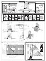
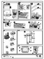
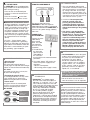
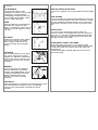
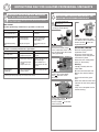
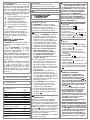
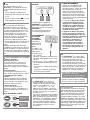
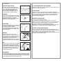
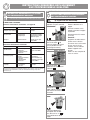
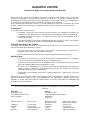
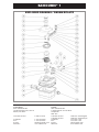
1
227
02.12
IND1
IMPORTANT
DO NOT RETURN ANY MERCHANDISE TO THE VENDOR
NE PAS RETOURNER DE MARCHANDISE AU VENDEUR
For Customer Service, Returns or Technical Questions, please call Saniflo’s technical support toll-free at
800-571-8191 (USA) or 800-363-5874 (CDN).
Pour le service client, les retours ou toute question technique, merci d’appeler le service technique de Saniflo au
numéro suivant : 800-571-8191 (USA) ou 800-877-8538 (CDN).
The user should retain these instructions for future reference • A lire attentivement et à conserver à titre d’information
This product must be installed in strict accordance with local plumbing codes.
Product should be installed by a licensed plumber.
Le produit doit être installé dans le respect des règlements sanitaires locaux.
Le produit doit être installé par un plombier qualifié.
226615
USA CDN
INSTALLATION AND MAINTENANCE INSTRUCTIONS
INSTRUCTIONS D’INSTALLATION ET D’ENTRETIEN
1
1-1/2”
1-1/2”
1
1-1/2”
1-1/2” / 4”
1-1/2” / 4”
2
x2
A
B
x2
C
x8
D
x4
40/60
E
x2
F
x2
G
x2
32/50
1-1/2” / 4”
x4
J
K
x1
N
O
x1
6 Ft
100/120
x1
x1
P
10/16
3
9"
18"
5"
3"
12-¾"
16-¼"
2-¾"
1-¾"
*
1-¼"
5-½"
13-¾"
1-½"
*
16-¾"
6
7
(meters)
(feet)
Vertical Height (feet)
Hauteur (pieds)
P1
11
36
10
33
9
30
8
26
7
23
1%
maxi 36 Ft
maxi 65 Ft
1%
29 Ft
1%
26 Ft
1%
6
20
5
16
4
13
3
10
23 Ft
1%
19 Ft
1%
16 Ft
1%
13 Ft
1%
2
1
10 Ft
7
3
80 100 120 140 160 180 200 220 240 260 280 300 320 340 360
P1
Flow Rate (gallons/min.)
Débit (gallons/min.)
SFA
maxi 131 Ft
maxi 164 Ft
maxi 197 Ft
maxi 229 Ft
SFA
maxi 262 Ft
maxi 295 Ft
1%
6 Ft
21 26 32 37 42 48 53 58 63 69 74 79 85 90 95
OK
maxi 98 Ft
maxi 328 Ft
1%
3 Ft
maxi 360 Ft
1%
SFA
8
11
8b
8d
1
1-½"
3
1-½"
1-½"
1-¼"
1-¼"
1-½"
1-½"
2
9"
8e
J
1
J
2
3
J
F
F
4"
J
8f
8g
3
8f1
SFA
8f2
8h
A
A
B
B
B
9
A
SANICUBIC® 1
R350
120 V - 60 Hz - 1 HP -
226615
1 DESCRIPTION
6 PERFORMANCE CURVE
8c
®
The SANICUBIC 1 is a lift station designed
to evacuate effluent from residential and
light commercial applications.
Please comply with all the installation
and maintenance specifications set out
in these instructions, and especially the
information marked with the following
signs:
«
» Failure to comply with this
information could entail safety
hazards for personnel,
«
» Information warning of the
presence of an electrical hazard,
«
» Instructions only for qualified
professional specialists,
«WARNING» Failure to comply with this
information could affect the normal
operation of the equipment.
Please contact our Customer service for
further information.
SANICUBIC 1 OPERATING
PRINCIPLE
SANICUBIC® 1 contains 1 pump equipped
with a high performance grinding system.
The SANICUBIC® 1 tank is fitted with 2 dip
tubes; one tube controls motor operation,
and the other one controls the alarm
system.
- Long pickup tube (normal operation): as
soon as the waste water level in the tank
reaches the triggering point in the long
tube, the pumping system starts up.
- Short pickup tube (inflow overload
operation): if the waste water level in the
tank reaches the upper point, a contact
is activated. This contact sets off a visual
alarm on the control panel. If the external
wired alarm is connected, this would give
you an audible and visual alarm. (See
section 9)
2 LIST OF PARTS SUPPLIED
3 DIMENSIONS
4 TECHNICAL DATA SANICUBIC® 1
Type
R350
Maximum discharge head
36 Ft
Voltage
120 V
Frequency
60 Hz
Volume
8.5 Gallons
Maximum power input
1 HP
Maximum current input
10 A
Electrical classification
I
Avg. water temp for optimum performance 104°F
Maximum temperature (intermittent)
160°F*
Protection index
IP67
Net weight (including accessories)
35 Lbs
*Hot water drain cycles from dishwashers or washing machines
5 FIELDS OF APPLICATION
This system is meant for residential and
light commercial applications.
7 RATIO OF HEIGHT/LENGTH
FOR DISCHARGE
8 INSTALLATION
The SANICUBIC® 1 must be installed in
compliance with local plumbing codes.
The equipment must be commissioned
and maintained by a qualified
professional specialist.
8a REGULATIONS
1- Attention: the space in which the
SANICUBIC® 1 is to be installed must
be large enough to leave at least 24’’
of working room around and above
the unit to facilitate such maintenance
work as may be required. There must
be sufficient lighting, and it must be
sufficiently well ventilated and protected from freezing.
2- Isolating valves (not supplied) must
be fitted on waste inlets (especially
the 4’’ inlets) and on the discharge
to ensure that any service/
maintenance may be carried out
safely.
3- The discharge pipe must be fitted
so as to avoid all back flow from the
drainage system (see the examples
in drawing 8g). Back flow can be
avoided by installing an anti-back flow
riser reaching a high point above the
maximum back flow level.
Comment: In the absence of local
information to the contrary, the
maximum back flow level corresponds
to street level (roadway, pavements,
etc.). Continue the discharge pipework
after the anti-backflow riser, using a
larger diameter pipe.
4- If the SANICUBIC® 1 is installed in a
space such as a pit for example, we
would recommend the fitting of a bilge
pump in case of flooding.
5- The lifting station must be vented with
an outlet at roof level.
6- The lifting station must be fixed to the
floor (see 8h ).
CONNECTING THE DISCHARGE PIPE
Remove the end cover or covers from the
back of the unit.
As the motor is fitted with a grinding
system, an 1-1/2’’ discharge pipe can be
used.
The discharge bend is at the center of the
unit, at the back (cf. 8b). Use a standard
1-1/2’’ coupling (not provided) to connect
it to the riser pipe and secure in place
with metal clamps.
The pump in the SANICUBIC ® 1 unit is
equipped with a check valve.
8b
CONNECTING SANITARY
EQUIPMENT TO THE LOWER
INLETS
If you want to install a shower or
a bath at the same level as the
Sanicubic 1, you must make sure
that the outlets of the connecting fixtures
are at least 10” above the lower inlet of
the Sanicubic 1. (ie. If connecting a rearoutlet toilet to the Sanicubic 1, the back
of the spigot (cl) should be 10” above the
bottom inlet of the Sanicubic 1.)
8d
CONNECTING THE 1-1/2’’ INLETS
Lower inlets (cf. 8d 1 )
Upper inlets (cf. 8d 2 )
• Cut off the end of the 1-1/2’’ inlet with
a saw
• Cut the sleeve D to suit the pipe
diameter: 1-1/4’’ or 1-1/2’’ (cf. 8d 3 )
• Fix the sleeve D on the inlet and on the
pipe, using the metal clamps.
CONNECTING THE 4’’ INLETS
Lower inlets (cf. 8e 1 )
1- Remove the plug from the side inlet.
2- Fix the sleeve F in place using the
metal clamp. J .
3- Fully insert the 4’’ tube in the other end
of the sleeve and fix it in place using
the other metal clamp. J .
Upper inlet (cf. 8e 2 )
1- Cut off the upper end of the 4’’ inlet
with a saw.
2- Fix the sleeve F in place using the
metal clamp J .
3- Fully insert the 4’’ tube in the other end
of the sleeve and fix it in place using
the other metal clamp J .
8e
8f CONNECTING THE VENT
1- VENT OF SANICUBIC® 1
The upper inlet must be used for the
vent. The vent pipe must be fitted up
to roof level.
Then fix the sleeve D in place using
the metal clamp C .
Fully insert the 1-1/2’’ tube in the
other end of the sleeve and fix it in
place using the other metal clamp C .
WARNING: Note that the vent
system should be a two-way air
vent. The use of mechanical vents,
air admittance valves or similar
devices are not permitted as these
are considered one-way air vent
systems.
The vent must be an open vent or
the unit will not operate.
2- VENTING THE ELECTRICAL SECTION
Connect the 8/11 clear PVC tubing ( N )
supplied to the keyboard on the
SANICUBIC® 1. The other end of this
tubing must be located between 3 Ft
and 6 Ft above the device to avoid
water getting into the electrical part
in the event of flooding.
Important: Do not pinch the tubing.
8h SECURING THE SANICUBIC® 1
UNIT TO THE FLOOR
The SANICUBIC 1 unit is equipped with
fittings to hold it on the floor and prevent
it from turning or moving.
1- Place the unit on the desired spot.
2- Locate the 2 holes for attachment to
the floor.
3- Place the 2 anchors A on the floor.
4- Fix the unit in place with the screws.
8I CONNECTING TO ELECTRICAL SUPPLY
1- All wiring should be in accordance with
the applicable electrical code in your
region. The grinding system requires a
single-phase 120-volt, 15 Amp. supply. When installed in a bathroom, the
receptacle should be 40 inches away
(in straight line) from a shower or bathtub. Connect only receptacle protected
by a ground fault circuit interrupter
(GFCI).
WARNING ! : Risk of electric shock this pump is supplied with a grounding
conductor an grounding type attachment
plug to reduce risk of electrical shock. be
certain that it is connected only to a properly grounding - type receptacle.
9 REMOTE ALARM BOX
1/ General alarms:
High level alarm:
If the water level inside the pump is
unusually high, the red LED alarm will light
up.(Also see note for External wired alarm)
EXTERNAL WIRED ALARM
REMOTE ALARM MODULE
red
general
alarm
LED
yellow
power
alarm
LED
The external alarm box of the
SANICUBIC® 1 does not require an
independent power supply. It is powered
via the circuit board of the SANICUBIC® 1.
In the case of a power outage, a battery
takes over.
CONNECTING
THE ALARM BOX
Connect the alarm
cable directly
to the control
panel. The cable
can extend for
15 Ft for ease of
installation.
1/ The red LED on
the alarm box
goes off (visual
and audible) at
the same time
that the LED on the mounted control
panel does.
2/ The yellow “power” LED shows the
status of the power supply for the
alarm box :
- LED on: normal power
- LED flashing: power supply is faulty.
Time alarm:
If the motor runs for over 1 minute, the
red alarm LED will light up.
2/ Resetting the general alarms:
The control panel button can only switch
off the red LED (it turns green) if the
problem causing the alarm is resolved.
3/ Power alarm:
If the green LED on the control panel
is flashing, it means that the electrical
power has temporarily been cut off.
UNIT ALARM
LED
GREEN : Power
RED : Alarm
TOUCH
Override
RESET Alarm
10 CONFORMITY WITH
STANDARDS
• SANICUBIC® 1 is eligible to bear
the CSA mark shown with adjacent
indicators “C” and “US”. The “C” and
“US” indicators adjacent to the CSA
mark signify that the product has been
tested according to the applicable
CSA (CAN) and ANSI/UL standards
for use in Canada and the USA.
This includes products eligible
bear the designation NTRL. NTRL
(Nationally Recognized Testing
Laboratory) is a designation awarded
by the American Occupational Safety
and Health Administration (OSHA) to
laboratories authorized to award the
certification according to American
standards.
11 COMMISSIONING
1 - Once the plumbing and electrical
connections have been made, check
that the connections are watertight
by letting water flow successively
through each inlet used. Make sure
that the unit is operating correctly by
carrying out at least two start cycles
with water to test the system.
2 - WARNING! Do not operate the
motor in override status (by
pressing the pushbutton on the
control box) until the pump have
been filled with water. Operation
without water damages the grinding
system.
3 - This device is not designed for
persons (including children) with
limited physical, sensory or mental
abilities, or those with minimal
experience and knowledge, unless
they are monitored and are given
the necessary instructions for
using the device, with the help of a
person responsible for their safety.
Monitor children and make sure
they do not play with the device.
12 USE
1- The SANICUBIC® 1 unit is designed
to drain off household waste water.
Any other use will invalidate the
guarantee. The unit is able to
handle the accidental flushing of
sanitary napkins such as condoms,
hygiene articles, etc. The disposal
of oils, solvents, acids or any other
potentially corrosive or explosive
liquids, etc, is not allowed.
2- WARNING: In the event of a power
failure, stop draining any water
from the equipment connected to
the SANICUBIC® 1 unit.
3- Do not install or use the unit in a
zone where there is risk of explosion.
13 MAINTENANCE
A visual check of the lift station must be
made once a month to make sure it is
operating correctly, and the installation
must be inspected regularly (once a
year) by a qualified person. Meanwhile
if encounter technical problems, please
ask our after-sales service for advice.
If the power supply cable of the unit is
damaged, it must be replaced by the
manufacturer or its after-sales service to
avoid all danger.
6 ADVICE
PIPE SUPPORTS
All sanitary pipe work must be
supported, in accordance with the pipe
manufacturer’s recommendations.
Avoid dipping or trapping, which may
cause the build up of residual “solids”
and sub- sequent blockage.
BENDS
Where possible long sweeping bends
should be used. Do not use short
elbows. If sweeping 90° elbows are not
available use two 45° elbows to make
a 90° turn.
PIPE WORK
All pipe work should be either copper,
PVC or CPVC (Do not use flexible
pipes). Hangers should not be less
than four feet apart to prevent pipe
rattling.
DISCHARGE
Never discharge directly into an open
drain, fixture, manhole or rainwater
drainpipe. It is illegal for it constitutes a
health hazard. Direct connections into
sanitary waste systems only, shall be
acceptable.
FREEZING
Ensure all pipe work susceptible to
freezing is adequately insulated or
heated. In unheated buildings, the toilet, piping and grinding unit must be
properly winterized with “RV or
plumbers” anti-freeze or drained
completely.
ELECTRICITY
Before attempting any maintenance or servicing, the unit must
be disconnected from the power source. The grinding
system must be connected to a Ground Fault Circuit
Interrupter.
VERTICAL INSTALLATION FIRST
If vertical lift is required, this must precede the horizontal pipe
run.
EASY ACCESS
The unit should be accessible and removable in the event of
maintenance being required. During the installation a full-port
ball valve should be installed at the base of any vertical discharge pipe work from the unit to allow easy service of the
unit.
GRAVITY FALL
The unit accepts wastewater by gravity; it does not
“vacuum” in water. All inlet pipe work must have a positive
gravity fall, (1/4" per foot). All horizontal piping from the grinding unit must also have a positive gravity fall to allow free
drainage when the pump stops.
NO DIAGONAL “UPHILL” PIPE RUNS
All discharge pipe work from the unit should run either
directly vertical upwards from it or in a horizontal plane (with
a small gravity flow) to the point of discharge. Pipe work
should not be
installed with diagonal upward slope from the unit to the
point of discharge.
INSTRUCTIONS ONLY FOR QUALIFIED PROFESSIONAL SPECIALISTS
16 DISMANTLING
15 WORK THAT MAY BE REQUIRED
ELECTRICAL INSTALLATION MUST BE CARRIED
OUT BY A PROFESSIONAL ELECTRICIAN
INSTRUCTIONS RESERVED EXCLUSIVELY FOR
QUALIFIED PROFESSIONAL SPECIALISTS
Before carrying out any other types of work, disconnect the Sanicubic ® 1
from the power supply.
DISCONNECT THE UNIT FROM
POWER SUPPLY (the green indicator
light must be off).
UNIT ALARM
Possible preliminary maintenance operations on the unit
PROBLEM
No motor starts and the
power yellow LED is off (*)
PROBABLE CAUSES
No power
The unit beeps to show that it
is no longer under power.
SOLUTIONS
F
Check your electrical
connections
16 4
The LED warning light is on
1 – Obstructed pump
2 – Blocked up pump
Press the override button
continuously to get the
pumps working
The LED flashing warning
light
Faulty detection system
Contact Saniflo after sales
service
Possible secondary maintenance operations
PROBLEM
PROBABLE CAUSES
SOLUTIONS
The motor does not start
but override works
1 – Faulty electronic card
2 – Faulty detection system
1 – Contact Saniflo after-sales
service
Pump running continuously
1 – Obstructed discharge pipe
1 – Remove obstruction from
the discharge pipe
2 – Check installation (**)
2 – Pump discharge height
too high
3 – Faulty electronic card
Pump starting up
intermittently
1 – The non-return valve is
leaking or broken
A
16 1
Unclip the cover.
Unscrew the metal clamp A
on the motor (the check valve
stays in place while the motor
is being repaired).
B
3 – Contact Saniflo after-sales
service
1 – Clean or change the valve
(*) A flashing yellow LED indicates that there has been a power cut.
(**) Warning: if pumping height is high, 90° elbows should be avoided.
If the faulty motor has to be
sent back to the manufacturer
remove screws F from the
inspection cover.
C
16 2
Unscrew the metal clamp
Remove the motor power
wires C from the screw
connector.
B
.
D
E
16 3
Remove the screws D from
the inspection cover.
Use the handle E to lift the
motor carefully.
INSTALLING A MOTOR
Remove the plug and the
inspection cover.
Screw the motor onto the
inspection cover and put the
cover back in place.
Reconnect the motor power
wires (cf. illustration ).
Warning:
Comply carefully with the
color code:
Blue wire with the blue wire
Brown wire with the brown
wire
Green wire with the green
wire
White wire with the white wire
Connect the unit to the power
supply.
Carry out a complete test for
commissioning.
4
5
6
7
8
9
10
11 12
1
2
3
1
Blue and brown alarm
2
Brown level pressure switch
3
Brown alarm pressure switch
4
White motor
5
White runnig capacitor
6
White runnig capacitor
7
Blue motor
8
Blue power cord
9
Brown power cord
10
Brown motor
11
Green/yellow motor
12
Green/yellow power cord
WARNING:
Each marked cable lug must be
isolated (7, 8, 9 and 10)
Attention : chaque cosse marquée
doit être isolée (7, 8, 9 et 10)
1 Brown / Blue: alarm
Marron / Bleu : alarme x2
2 Brown: level pressure switch
4 White: motor
Blanc : moteur
5 White: running capacitor
Marron : pressostat niveau
Blanc : condensateur
3 Brown: alarm pressure switch
6 White: running capacitor
Marron : pressostat alarm
Blanc : condensateur
7 Blue: motor
10 Brown: motor
Bleu : moteur
Marron : moteur
8 Blue: power cord
11 Green/yellow: motor
Bleu : cordon alimentation
9 Brown: power cord
Marron : cordon alimentation
Vert/jaune : moteur
12 Green/yellow: power cord
Vert/jaune : cordon alimentation
LIMITED WARRANTY
Warranty period two-year from date of purchase
Subject to the conditions listed below, SFA-SANIFLO INC. (hereinafter called the «Company»)
guarantees to repair or at its option replace the product or any component thereof, which, in the
opinion of the Company, is faulty or below standard as a result of inferior workmanship or materials.
If replacement is to be issued, this will only be extended to the first 180 days starting from the date
of purchase. Warranty repairs will apply after such date up to the warranty’s date of conclusion.
CONDITIONS
The conditions of this guarantee are:
1.The product must not have been subjected to misuse, neglect, accident or damaging
products, in accordance with the paragraph «USAGE» of these Installation Instructions.
2.The product must be connected to the proper electrical supply as per the installation
manual.
3.The alleged fault or defect must be notified to the company, within the warranty period.
PART OR PRODUCT EXCHANGE
The product will be exchange, free of charge, at the original resellers place of business only, upon
the followings conditions being fullfilled:
1 The customer need a «return authorization» number from the company to authorize and
validate the exchange.
2 The customer must supply a copy of their invoice to validate the request for an exchange.
LIMITATIONS
1.Cost of disconnection and reconnection (i.e. labor charges) are not covered by the
warranty and are end-users responsability.
2.Cost of mail or freight when a part or parts of the system have to be repaired at the
company are not covered by this warranty.
3.In no event shall the company be liable for any special, incidental or consequential
damage, loss, or injury of whatsoever nature or kind arising from or in connection with the
product or any component thereof.
4.The guarantee is transferable only when the product remains at the same premises as
where it was installed initialy.
Except as set forth in this Limited Warranty, the company disclaims all other warranties, express
or implied, with respect to the product or any component thereof including, but not limited to, all
implied warranties for merchantability and fitness for a particular purpose
For service or for further inquiries, please contact one of the following addresses:
United States
SFA-SANIFLO INC.
105 Newfield Avenue, Suite A
Edison, NJ 08837
Canada
SFA-SANIFLO INC.
1-685 Speedvale Avenue West
Guelph ON
N1K 1E6
Toll Free:
1-800-571-8191
Telephone:
Fax:
E-mail.:
Web Site:
1-732-225-6070
1-732-225-6072
[email protected]
www.saniflo.com
Toll Free:
Toll Free:
Telephone:
Fax:
E-mail.:
Web Site:
1-800-363-5874 English
1-800-877-8538 French
1-519-824-1134
1-519-824-1143
[email protected]
www.saniflo.ca
1 DESCRIPTION
5 USAGES
®
Le SANICUBIC 1 est une station de
relevage conçue pour évacuer les effluents
provenant d’un usage domestique ou d’un
usage commercial léger. Prière de respecter
toutes les instructions d’installation et
d’entretien du présent mode d’emploi et, en
particulier, les informations correspondant
aux symboles suivants :
«
» Le non-respect de cette indication
risque de mettre en danger la
sécurité des personnes.
«
» Cette indication avertit de la
présence d'un danger électrique.
«
» Ces instructions sont réservées
exclusivement aux professionnels
qualifiés.
« AVERTISSEMENT » Le non-respect
de cette indication risque de nuire au
fonctionnement normal de l'équipement.
Pour de plus amples renseignements,
prière de communiquer avec le service à
la clientèle.
SANICUBIC® 1 PRINCIPE DE
FONCTIONNEMENT
Le SANICUBIC® 1 comprend une pompe
équipée d'un système de broyage très
performant.
La cuve du SANICUBIC® 1 est équipée
de deux tubes plongeurs; l’un d’eux
commande le fonctionnement du moteur
et l'autre, le système d'alarme.
- Tube plongeur long (fonctionnement
normal) : dès que le niveau des effluents de
la cuve atteint le point de déclenchement
du tube long, le système de pompage se
met en route.
- Tube plongeur court (fonctionnement
anormal) : si les effluents atteignent
le niveau supérieur dans la cuve,
ils établissent un contact. Ce contact
déclenche une alarme visuelle et sonore,
la diode électroluminescente d'alarme
(DEL) du panneau de commande passe
au rouge.
2 LISTE DES PIÈCES FOURNIES
3 DIMENSIONS
4 DONNÉES TECHNIQUES DU
SANICUBIC® 1
Type
Hauteur de refoulement maximale
Tension
Fréquence
Volume
Puissance absorbée maximale
Intensité absorbée maximale
Classe électrique
Température moyenne de l'eau
pour une performance optimale
Température maximale
(par intermittence)
Indice de protection
Poids net (accessoires inclus)
R350
36 pi
120 V
60 Hz
8,5 gallons
1 CV
10 A
I
104 °F
160 °F*
IP67
35 lb
* Cycles d’évacuation d’eau chaude du lave-vaisselle ou de la
machine à laver
Ce système est conçu pour usage
résidentiel ou usage commercial léger.
6 COURBE DE PERFORMANCE
7 RAPPORT HAUTEUR/
LONGUEUR POUR
L’ÉVACUATION
8 INSTALLATION
Le SANICUBIC® 1 doit être installé
conformément aux codes de plomberie
en vigueur. La mise en service et
l’entretien de l’équipement doivent être
réalisés par un professionnel qualifié.
RÉGLEMENTATIONS
1- Attention : le SANICUBIC® 1 doit être
installé dans un local suffisamment
grand pour disposer d’un espace de
travail d’au moins 24 po autour et
au-dessus de l’unité afin de permettre
la réalisation des travaux d’entretien
éventuellement nécessaires. Ce local
doit disposer d’un éclairage suffisant
et être bien ventilé et protégé du gel.
2- Des vannes d’arrêt (non fournies)
doivent être installées sur les
entrées d’effluents (en particulier
les entrées de 4 po) ainsi que sur
la conduite d’évacuation pour
s’assurer que l’entretien s’effectue
en toute sécurité.
3- Cette conduite d’évacuation doit être
conçue de façon à éviter tout reflux
des égouts (voir les illustrations à la
figure 8g). Le reflux des égouts peut
être évité en installant une boucle antiretour située au-dessus du niveau du
reflux maximum.
Commentaires : Sauf indication
contraire des autorités locales, le
niveau de reflux maximal correspond
au niveau de la rue (chaussée, trottoir,
etc.). Prolonger le conduit après la
boucle anti-retour, en utilisant un tuyau
de diamètre supérieur.
4- Si le SANICUBIC® 1 est installé dans
un espace comme un puits, il est
recommandé de poser une pompe
auxiliaire en cas d’inondation.
5- La station de relevage doit être ventilée par une sortie au niveau du toit.
6- La station de relevage doit être fixée
au sol (cf. 8h ).
8a
RACCORDEMENT DE LA CONDUITE
D’ÉVACUATION
Retirer le ou les couvercles d’extrémité
qui se trouvent à l’arrière de l’appareil.
Comme le moteur est équipé d’un système
de macération, il est possible d’utiliser un
tuyau d'évacuation de 1½ po. Le coude de
refoulement se trouve au centre de l’unité,
à l’arrière 8b). Utiliser un raccord standard
de 1½ po (non fourni) pour le connecter
à la colonne montante et le fixer en place
avec des colliers métalliques.
La pompe du SANICUBIC ® 1 est équipée
d’un clapet anti-retour.
8b
RACCORDEMENT D’APPAREILS
SANITAIRES AUX ENTRÉES BASSES
Pour installer une douche ou une
baignoire au même niveau que le
SANICUBIC® 1, il faut s’assurer que
les bondes d’évacuation des appareils
sont situées à une hauteur minimale de
10 po au-dessus du SANICUBIC® 1.
(Autrement dit, pour brancher l’évacuation
arrière d’une toilette au SANICUBIC® 1,
l’arrière de l’entrée mâle (cl) doit se situer
au moins 10 po au-dessus de la bonde
arrière du SANICUBIC® 1.)
8c
RACCORDEMENT DES ENTRÉES
DE 1½ po
Entrées basses (cf. 8d 1 )
Entrées hautes (cf. 8d 2 )
• Découper l'extrémité de l’entrée de
1½ po à la scie.
• Découper le manchon D au diamètre du
tuyau : 1¼ po ou 1½ po (cf. 8d 3 )
• Fixer le manchon D sur l'entrée et sur le
tuyau à l’aide de colliers métalliques.
8d
RACCORDEMENT DE L’ENTRÉE
DE 4 po
Entrées basses (cf 8e 1 )
1- Retirer le bouchon de l'entrée latérale.
2- Fixer le manchon F en place à l’aide du
collier métallique J .
3- Insérer complètement le manchon
de 4 po dans l’autre extrémité du
manchon et le fixer avec l’autre collier
métallique J .
Entrée haute (cf. 8e 2 )
1- Découper l’extrémité haute de l’entrée
de 4 po à la scie.
2- Fixer le manchon F en place avec le
collier métallique J .
3- Enfoncer complètement le tube de 4 po
dans l’autre extrémité du manchon et le
fixer à l’aide de l’autre collier métallique
J.
8e
RACCORDEMENT DE L’ÉVENT
1- ÉVENT DU SANICUBIC® 1
L’entrée haute est destinée à la
ventilation. La conduite d’aération
doit être installée jusqu’au niveau
du toit. Fixer alors le manchon D en
place à l’aide du collier métallique C
. Enfoncer complètement le tube de
1½ po dans l’autre extrémité du manchon et le fixer avec l’autre collier
métallique C .
ATTENTION : Noter que le système
de ventilation devrait être une prise
d’air à double sens. L’utilisation
d’évents mécaniques, soupapes
d’admission d’air ou dispositifs similaires n’est pas autorisée, car ils sont
considérés comme des systèmes
d’aération à sens unique.
L’évent doit être ouvert sinon l’appareil ne fonctionnera pas.
8f
2- MISE À L’AIR DE LA PARTIE ÉLECTRIQUE
Brancher le tuyau en PVC transparent
de 8/11 ( N ) fourni au clavier situé sur
le SANICUBIC®1. L’autre extrémité de
ce tube doit se situer entre trois et six
pieds au-dessus de l’appareil pour
éviter que l’eau ne pénètre dans la
partie électrique en cas d’inondation.
Important : ne pas pincer ce tuyau.
8h INSTALLATION DU SANICUBIC® 1
AU SOL
Pour son installation au sol, le
SANICUBIC® 1 est équipé de fixations
afin de l’empêcher de basculer ou de
bouger.
1 - Placer l’appareil à l’endroit voulu.
2 - Repérer les deux trous pour la fixation
au sol.
3 - Placer les deux ancrages A sur le sol.
4 - Fixer l’appareil à l’aide des vis.
RACCORDEMENT ÉLECTRIQUE
Tous les branchements électriques
doivent être conformes au code de
l’électricité en vigueur dans votre région.
Le système de broyage requiert une alimentation monophasée de 120 V - 15 A.
Si la prise de courant est située dans
une salle de bains, elle doit être à une
distance de 40 pouces (en ligne directe)
d’une douche ou d’une baignoire.
Ne connectez l’appareil qu’à une prise
de courant protégée par un coupe-circuit
en cas de défaut de mise à la terre du
neutre.
Attention : risque de choc électrique cet appareil est muni d’une prise de terre
(GFI) afin de réduire le risque d’électrocution. Vérifiez que votre appareil est branché sur un circuit électrique avec prise de
terre.
8I
9 FONCTIONNEMENT DE L’ALARME
1/ Alarmes générales :
Alarme de niveau élevé :
Si le niveau d’eau dans la pompe est
anormalement élevé, la DEL d’alarme
rouge s’allume (voir aussi la remarque
concernant le module d’alarme à distance
déporté).
Alarme temporelle :
Si le moteur tourne depuis plus d’une
minute, la DEL rouge de l’alarme s’allume.
2/ Réinitialisation des alarmes
générales :
La touche du panneau de commandes
ne permet d’éteindre la DEL rouge (elle
passe au vert) que si la défaillance ayant
déclenché l’alarme est résolue.
3/ Alarme principale :
Si la DEL verte du panneau de
commandes clignote, cela indique une
coupure temporaire de l’alimentation du
réseau.
DEL D'ALARME DE L’UNITÉ
DEL
VERTE : Alimentation
ROUGE : Alarme
TOUCHE
Marche forcée
RÉINITIALISER
l’alarme
MODULE D’ALARME À DISTANCE
DÉPORTÉ
red
rouge
general
alarme
alarm
générale
LED
DEL
yellow
jaune
power
alarme
alarm
générale
LED
DEL
Le boîtier d’alarme déporté du
SANICUBIC® 1 ne nécessite pas
d’alimentation indépendante. Il est
alimenté par la carte de circuit du
SANICUBIC® 1.
En cas de coupure de courant,
l’accumulateur prend le relais.
RACCORDEMENT
DU BOÎTIER
D’ALARME
À L’APPAREIL
Connecter le
câble d'alarme
directement au
boîtier.
Le CUBIC 1 est
livré avec 5 m de
câble alarme.
1/ La DEL rouge
de « l’alarme
générale » reproduit le fonctionnement
de la DEL correspondante sur la carte
de base.
2/ La DEL jaune « réseau » indique l’état
de l’alimentation du boîtier d’alarme à
distance :
- Allumée fixe = module alimenté par le
réseau.
- Clignotante = défaut d’alimentation
du réseau pour le module.
10 CONFORMITÉ AUX NORMES
• Le SANICUBIC® 1 est autorisé à
porter la marque de l’Association
canadienne de normalisation (CSA)
avec les signes adjacents « C » et
« US ». Les signes « C » et « US»
indiquent que le produit a été testé
selon les normes CSA (CAN) et ANSI/
UL pour une utilisation au Canada et
aux États-Unis.
Ces normes comprennent les produits
admissibles qui portent la désignation
NTRL (Nationally Recognized Testing
Laboratory), une appellation attribuée
par l’American Occupational Safety
and Health Administration (OSHA)
aux laboratoires habilités à décerner
une certification selon les normes
américaines.
11 MISE EN SERVICE
1 - Une fois les raccordements de
plomberie et les branchements
électriques réalisés, vérifier l’étanchéité
des raccordements en laissant
couler l’eau successivement dans
chaque entrée utilisée. S’assurer du
bon fonctionnement de l’appareil en
effectuant un essai en eau au moins
durant deux cycles de démarrage pour
tester le système.
2 - ATTENTION ! Ne pas faire tourner
le moteur en marche forcée (en
appuyant sur le bouton-poussoir
du tableau de commande) avant
d’avoir mis la pompe en eau. Un
fonctionnement à sec détériore le
système de macération.
3 - L’appareil ne doit pas être utilisé
par des personnes (y compris les
enfants) ayant de faibles capacités
physiques, mentales ou sensorielles,
sans expérience ou avec des
compétences insuffisantes, à
moins qu’elles ne soient sous
la surveillance d’une personne
responsable de leur sécurité ou
formées par cette personne en ce
qui concerne l’utilisation de cet
appareil.
12 UTILISATION
1- Le SANICUBIC® 1 est conçu pour
évacuer les eaux usées domestiques.
Toute autre utilisation entraînera
l’annulation de la garantie. L’appareil
est capable de gérer l’élimination
accidentelle de serviettes, préservatifs,
articles d’hygiène, etc. L’élimination des
huiles, des solvants, acides ou autres
liquides potentiellement corrosifs ou
explosifs, etc. n’est pas autorisée.
2- ATTENTION : En cas de coupure
de courant, arrêter tout
écoulement d’eau provenant des
appareils reliés au SANICUBIC® 1.
3- Ne pas installer ni utiliser l’appareil
dans une zone à risque d’explosion.
13 ENTRETIEN
Une vérification visuelle de la station de
relevage doit être faite une fois par mois
pour s’assurer de son bon fonctionnement, et l’installation doit être inspectée
régulièrement (une fois par an) par une
personne qualifiée. Toutefois, en cas de
problèmes techniques, prière de demander conseil auprès du service après-vente.
Si le câble d’alimentation de l’appareil est
endommagé, il doit être remplacé par le
fabricant ou le service après-vente afin
d’éviter tout danger.
6 CONSEILS
ANCRAGE DES TUYAUX
LA TUYAUTERIE VERTICALE D’ABORD
Tous les tuyaux des installations sanitaires doivent être ancrés conformément
aux recommandations du fabricant
pour les empêcher de pendre, car ils
pourraient alors être bloqués par une
accumulation de “matières solides ”.
Lorsqu’on installe des tuyaux à la verticale, il faut les poser avant
de poser les tuyaux horizontaux.
COURBES
Dans la mesure du possible, utilisez des
courbes de tuyau plutôt que des coudes.
Si des coudes de 90° ne sont pas
disponibles, utilisez deux coudes de 45°
pour former une courbe de 90°.
TUYAUTERIE
Tous les tuyaux doivent être en cuivre ou
en plastique soudé au solvant. Il ne faut
pas utiliser de tuyaux flexibles.
Les pendards doivent être espacés d’au
moins quatre pieds pour empêcher les
tuyaux de cogner.
VIDANGE
Ne jamais évacuer les eaux usées
directement dans un égout à ciel ouvert,
un trou d’homme ou un drain pour les
eaux de pluie. Cela est illégal et constitue
un danger pour la santé. Seuls les
branchements directs dans les systèmes
de déchets sanitaires sont acceptables.
GEL
Assurez-vous que tout tuyau susceptible
de geler est bien isolé ou chauffé. Dans
les immeubles non chauffés, la toilette, la
tuyauterie et l’ensemble broyeur-pompe
doivent être protégés contre le gel avec
de l’antigel de « véhicule de plaisance »
ou vidés complètement.
ÉLECTRICITÉ
Avant d’entreprendre des travaux d’entretien ou de dépannage, il
faut débrancher l’appareil de la source d’alimentation en électricité. Le système de broyage doit être protégé par un coupe-circuit
en cas de défaut de mise à la terre du neutre.
ACCÈS FACILE
Il faut avoir accès à l’ensemble broyeur-pompe et pouvoir le
déposer en cas de réparation. Au moment de l’installation, il faut
poser une purge et une vanne d’arrêt à passage intégral à la
base de tout tuyau d’évacuation vertical, pour permettre de
réparer facilement l’appareil.
DESCENTE PAR GRAVITÉ
Les eaux usées se déversent dans
l’ensemble broyeur-pompe par gravité. Elles ne sont pas
aspirées. Tous les tuyaux d’arrivée doivent assurer l’écoulement
absolu par gravité (1/4 po par pied). Les tuyaux d’évacuation
horizontaux sortant de l’ensemble broyeur-pompe
doivent aussi assurer l’écoulement absolu par gravité, pour que
le drainage se fasse librement lorsque la pompe s’arrête.
PAS DE TUYAUX EN DIAGONALE
Tous les tuyaux de vidange sortant de l’appareil doivent soit
monter directement à la verticale, soit être en position horizontale
(avec un léger écoulement par gravité) jusqu’au point
d’évacuation. Il ne faut pas installer de tuyaux en diagonale entre
l’appareil et le point d’évacuation.
INSTRUCTIONS RÉSERVÉES EXCLUSIVEMENT
AUX PROFESSIONNELS QUALIFIES
15 INTERVENTIONS ÉVENTUELLES
16 DÉMONTAGE DU MOTEUR
INSTRUCTIONS RÉSERVÉES EXCLUSIVEMENT
AUX PROFESSIONNELS QUALIFIES
Pour toutes autres interventions, débrancher la prise de courant
ALARME SUR L'APPAREIL
Premières interventions éventuelles sur l'appareil
ANOMALIE CONSTATÉE
CAUSES PROBABLES
Vérifier l’installation
électrique
LED alarme allumé
1 – Pompe bouchée
2 – Pompe bloquée
Faire fonctionner la pompe
(bouton marche forçée) par
impulsions répétées
LED clignote
Problème de détection
Consulter le service après
vente SANIFLO
Deuxièmes interventions éventuelles
CAUSES PROBABLES
REMÈDES
Pas démarrage moteur
mais MF fonctionne
1 – Carte électronique
défectueuse
2 – Système de détection
défectueux
1 – Consulter le service
après vente SANIFLO
Fonctionnement en
permanent de la pompe
1 – Tuyau d’évacuation
bouché
2 – Hauteur de refoulement
trop élevé
3 – Carte électronique
défectueuse
1 – Déboucher la conduite
d’évacuation
2 – Revoir l’installation (**)
1 – Le clapet anti-retour
est soit fuyard
soit cassé
1 – Nettoyer ou changer
le clapet
Remise en route intermittente
de la pompe
METTRE L’APPAREIL HORS TENSION
(le voyant vert doit être éteint).
Sirène indiquant que
REMONTAGE DU MOTEUR
l’appareil n’est plus alimenté.
Retirer le bouchon et la
trappe.
Revisser le moteur sur la
trappe et remettre la trappe
en position.
Reconnecter les fils moteur
(cf visuel)
REMÈDES
Le moteur ne démarre
Appareil hors tension
+ LED jaune secteur éteinte (*)
ANOMALIE CONSTATÉE
INSTRUCTIONS RÉSERVÉES EXCLUSIVEMENT
AUX PROFESSIONNELS QUALIFIES
A
16 1
Déclipser le capot.
Dévisser le collier A du
moteur (le clapet anti-retour
reste en position lors du
dépannage du moteur).
B
C
3 – Consulter le service après
vente SANIFLO
16 2
(*) Si vous retrouvez l’appareil avec la LED jaune clignotant , une coupure de courant est survenue.
(**) Attention éviter au maximum les coudes à 90° si la hauteur de relevage est importante.
MF : marché forçée
Dévisser le collier B .
Débrancher les fils moteurs
du bornier C .
D
E
16 3
Dévisser les vis D de la
trappe. Utiliser la poignée E
pour soulever le moteur avec
précaution.
F
16 4
Si le moteur défectueux
doit repartir chez le fabricant, dévisser les vis F du
moteur défectueux de la
trappe.
Attention :
Respecter le code couleur :
Fil bleu avec le fil bleu
Fil marron avec le fil marron
Fil vert avec le fil vert
Fil blanc avec le fil blanc
Mettre l’appareil sous
tension.
Refaire un test complet de
mise en service.
4
5
6
7
8
9
10
11 12
1
2
3
1
Blue and brown alarm
2
Brown level pressure switch
3
Brown alarm pressure switch
4
White motor
5
White runnig capacitor
6
White runnig capacitor
7
Blue motor
8
Blue power cord
9
Brown power cord
10
Brown motor
11
Green/yellow motor
12
Green/yellow power cord
WARNING:
Each marked cable lug must be
isolated (7, 8, 9 and 10)
Attention : chaque cosse marquée
doit être isolée (7, 8, 9 et 10)
1 Brown / Blue: alarm
Marron / Bleu : alarme x2
2 Brown: level pressure switch
4 White: motor
Blanc : moteur
5 White: running capacitor
Marron : pressostat niveau
Blanc : condensateur
3 Brown: alarm pressure switch
6 White: running capacitor
Marron : pressostat alarm
Blanc : condensateur
7 Blue: motor
10 Brown: motor
Bleu : moteur
Marron : moteur
8 Blue: power cord
11 Green/yellow: motor
Bleu : cordon alimentation
9 Brown: power cord
Marron : cordon alimentation
Vert/jaune : moteur
12 Green/yellow: power cord
Vert/jaune : cordon alimentation
GARANTIE LIMITÉE
Garantie de deux ans à partir de la date d’achat
Sous réserve du respect des conditions énoncées ci-dessous, SFA-SANIFLO INC. (ci-dessous
appelée “la Compagnie”) garantit qu’elle réparera ou remplacera, à son gré, le produit ou l’une
quelconque de ses pièces, qui de l’avis de la Compagnie, se trouve défectueux ou ne répond pas à
la performance demandée du fait d’un défaut de fabrication ou de matériau.
Si un remplacement doit être effectué, cela sera prolongé de 180 jours à compter de la date
d’achat. La garantie des réparations s’appliquera après cette date jusqu’à la fin de la garantie.
CONDITIONS
Les conditions de la garantie sont :
1. Le produit ne doit pas avoir subi de mauvais traitement, de négligence, d’accident ou
d’exposition à des produits nocifs, conformément au paragraphe intitulé «UTILISATION»;
2. Le produit doit avoir été branché à une prise de courant comme celle indiquée dans le
manuel d’installation ;
3. Le présumé défaut ou la présumée défaillance doit être signalé (e), sinon à l’installateur,
du moins à la Compagnie, durant la période de garantie en vigueur.
ÉCHANGE DE PIÈCE OU DE PRODUIT
Le produit sera échangé sans frais, à l’établissement de détail où il a été acheté seulement, sous
réserve du respect des conditions suivantes :
- Le client devra être en possession d’un numéro «d’autorisation de retour» de la
Compagnie afin d’autoriser et de valider l’échange ;
- Le client doit fournir une copie de sa facture pour valider la demande d’échange.
RESTRICTIONS
1. La garantie ne couvre pas les frais de branchement et rebranchement de l’installation
(c.-à-d. les frais de main-d’œuvre) qui sont à la charge du client ;
2. La garantie ne couvre pas les frais d’expédition ou de transport quand une pièce ou des
pièces de l’appareil doit(vent) être réparé(e)s à l’usine ;
3. En aucun cas la Compagnie ne sera tenue responsable des dommages accessoires ou
indirects, pertes ou blessures, de quelle que nature que ce soit, résultant de l’utilisation
du produit, ou de l’un de ses composants ;
4. La garantie est transférable seulement si l’appareil demeure à l’endroit où il fut installé
initialement.
Sauf pour ce qui est des termes de cette garantie limitée, la Compagnie n’accepte aucune autre
garantie, implicite ou explicite, ayant trait au produit ou à tout composant y afférent, incluant sans
toutefois s’y limiter, toute autre garantie implicite quant à la valeur marchande ou l’adaptabilité de
ce produit à une fin particulière.
Pour le service et d’autres demandes de renseignements, veuillez appeler à l’une des adresses indiquées
ci-dessous.
États-Unis
SFA-SANIFLO INC.
105 Newfield Avenue, Suite A
Edison, NJ 08837
Canada
SFA-SANIFLO INC.
1-685 Speedvale Avenue West
Guelph ON
N1K 1E6
Numéro sans frais :
800-571-8191
Téléphone :
Télécopie :
C.élec. :
Site Web :
732-225-6070
732-225-6072
[email protected]
www.saniflo.com
Numéro sans frais :
Numéro sans frais :
Téléphone :
Télécopie :
C.élec. :
Site Web :
800-363-5874 Anglais
800-877-8538 Français
519-824-1134
519-824-1143
[email protected]
http://www.saniflo.ca
SANICUBIC® 1
EXPLODED DRAWING / DESSIN ÉCLATÉ
United States
SFA-SANIFLO INC.
105 Newfield Avenue, Suite A
Edison, NJ 08837
Canada
SFA-SANIFLO INC.
1-685 Speedvale Avenue West
Guelph ON
N1K 1E6
Customer toll free:
1-800-571-8191
Telephone:
Fax:
E-mail.:
Web Site:
1-732-225-6070
1-732-225-6072
[email protected]
www.saniflo.com
Customer toll free:
Customer toll free:
Telephone:
Fax:
E-mail.:
Web Site:
1-800-363-5874 English
1-800-877-8538 Français
1-519-824-1134
1-519-824-1143
[email protected]
www.saniflo.ca/fr