1
Installation Manual
P/N 20001700, Rev. B
August 2005
Micro Motion®
Model 1700 and
Model 2700 Transmitters
Installation Manual
©2005, Micro Motion, Inc. All rights reserved. Micro Motion is a registered trademark of Micro Motion, Inc. The Micro Motion
and Emerson logos are trademarks of Emerson Electric Co. All other trademarks are property of their respective owners.
Contents
Chapter 1
Before You Begin . . . . . . . . . . . . . . . . . . . . . . . . . . . . . . . . . . . . . 1
1.1
1.2
1.3
1.4
1.5
1.6
1.7
1.8
Chapter 2
2.4
2.5
2.6
2.7
2.8
Overview . . . . . . . . . . . . . . . . . . . . . . . . . . . . . . . . . . . . . . . . . . . . . . . . . . . . . . . . . . . 5
Installation architecture . . . . . . . . . . . . . . . . . . . . . . . . . . . . . . . . . . . . . . . . . . . . . . . . 5
Determining an appropriate location . . . . . . . . . . . . . . . . . . . . . . . . . . . . . . . . . . . . . . 7
2.3.1
Environmental requirements . . . . . . . . . . . . . . . . . . . . . . . . . . . . . . . . . . . 7
2.3.2
Hazardous area classifications . . . . . . . . . . . . . . . . . . . . . . . . . . . . . . . . . 7
2.3.3
Power source . . . . . . . . . . . . . . . . . . . . . . . . . . . . . . . . . . . . . . . . . . . . . . . 7
2.3.4
Maximum cable lengths . . . . . . . . . . . . . . . . . . . . . . . . . . . . . . . . . . . . . . . 9
2.3.5
Accessibility for maintenance. . . . . . . . . . . . . . . . . . . . . . . . . . . . . . . . . . . 9
Mounting the transmitter . . . . . . . . . . . . . . . . . . . . . . . . . . . . . . . . . . . . . . . . . . . . . . . 9
2.4.1
Integral installations . . . . . . . . . . . . . . . . . . . . . . . . . . . . . . . . . . . . . . . . . 10
2.4.2
4-wire remote or remote core processor with remote
transmitter installations . . . . . . . . . . . . . . . . . . . . . . . . . . . . . . . . . . . . . . 11
2.4.3
9-wire remote installations . . . . . . . . . . . . . . . . . . . . . . . . . . . . . . . . . . . . 12
Mounting the remote core processor . . . . . . . . . . . . . . . . . . . . . . . . . . . . . . . . . . . . 13
Grounding the flowmeter components . . . . . . . . . . . . . . . . . . . . . . . . . . . . . . . . . . . 15
Supplying power . . . . . . . . . . . . . . . . . . . . . . . . . . . . . . . . . . . . . . . . . . . . . . . . . . . . 16
Rotating the display. . . . . . . . . . . . . . . . . . . . . . . . . . . . . . . . . . . . . . . . . . . . . . . . . . 16
Wiring the Transmitter to the Sensor . . . . . . . . . . . . . . . . . . . . . . . 19
3.1
3.2
3.3
3.4
3.5
Chapter 4
1
1
2
2
3
3
3
4
Installing the Transmitter . . . . . . . . . . . . . . . . . . . . . . . . . . . . . . . 5
2.1
2.2
2.3
Chapter 3
Overview . . . . . . . . . . . . . . . . . . . . . . . . . . . . . . . . . . . . . . . . . . . . . . . . . . . . . . . . . . .
Safety . . . . . . . . . . . . . . . . . . . . . . . . . . . . . . . . . . . . . . . . . . . . . . . . . . . . . . . . . . . . .
Flowmeter components . . . . . . . . . . . . . . . . . . . . . . . . . . . . . . . . . . . . . . . . . . . . . . . .
Transmitter type, installation type, and outputs option board . . . . . . . . . . . . . . . . . . .
Abbreviations used in this manual. . . . . . . . . . . . . . . . . . . . . . . . . . . . . . . . . . . . . . . .
Transmitter installation procedures . . . . . . . . . . . . . . . . . . . . . . . . . . . . . . . . . . . . . . .
Flowmeter documentation . . . . . . . . . . . . . . . . . . . . . . . . . . . . . . . . . . . . . . . . . . . . . .
Micro Motion customer service . . . . . . . . . . . . . . . . . . . . . . . . . . . . . . . . . . . . . . . . . .
Overview . . . . . . . . . . . . . . . . . . . . . . . . . . . . . . . . . . . . . . . . . . . . . . . . . . . . . . . . . .
Cable types . . . . . . . . . . . . . . . . . . . . . . . . . . . . . . . . . . . . . . . . . . . . . . . . . . . . . . . .
3.2.1
4-wire cable . . . . . . . . . . . . . . . . . . . . . . . . . . . . . . . . . . . . . . . . . . . . . . .
3.2.2
9-wire cable . . . . . . . . . . . . . . . . . . . . . . . . . . . . . . . . . . . . . . . . . . . . . . .
Wiring for 4-wire remote installations . . . . . . . . . . . . . . . . . . . . . . . . . . . . . . . . . . . .
Wiring for 9-wire remote installations . . . . . . . . . . . . . . . . . . . . . . . . . . . . . . . . . . . .
Wiring for remote core processor with remote transmitter installations. . . . . . . . . . .
19
19
20
20
20
21
23
Output Wiring – Model 1700/2700 AN Transmitters . . . . . . . . . . . . . 29
4.1
4.2
4.3
Overview . . . . . . . . . . . . . . . . . . . . . . . . . . . . . . . . . . . . . . . . . . . . . . . . . . . . . . . . . . 29
Output terminals and output types . . . . . . . . . . . . . . . . . . . . . . . . . . . . . . . . . . . . . . 29
Output wiring . . . . . . . . . . . . . . . . . . . . . . . . . . . . . . . . . . . . . . . . . . . . . . . . . . . . . . . 29
Transmitter Installation: Model 1700 and 2700 Transmitters
iii
Contents
Chapter 5
Output Wiring – Model 1700/2700 IS Transmitters . . . . . . . . . . . . . 33
5.1
5.2
5.3
5.4
Chapter 6
33
33
34
34
36
37
37
39
39
Output Wiring – Model 2700 CIO Transmitters . . . . . . . . . . . . . . . . 41
6.1
6.2
6.3
6.4
6.5
6.6
Chapter 7
Overview . . . . . . . . . . . . . . . . . . . . . . . . . . . . . . . . . . . . . . . . . . . . . . . . . . . . . . . . . .
Output terminals and output types . . . . . . . . . . . . . . . . . . . . . . . . . . . . . . . . . . . . . .
Safe area output wiring . . . . . . . . . . . . . . . . . . . . . . . . . . . . . . . . . . . . . . . . . . . . . . .
5.3.1
Safe area mA output wiring . . . . . . . . . . . . . . . . . . . . . . . . . . . . . . . . . . .
5.3.2
Safe area frequency/discrete output wiring . . . . . . . . . . . . . . . . . . . . . . .
Hazardous area output wiring . . . . . . . . . . . . . . . . . . . . . . . . . . . . . . . . . . . . . . . . . .
5.4.1
Hazardous area safety parameters . . . . . . . . . . . . . . . . . . . . . . . . . . . . .
5.4.2
Hazardous area mA output wiring . . . . . . . . . . . . . . . . . . . . . . . . . . . . . .
5.4.3
Hazardous area frequency/discrete output wiring . . . . . . . . . . . . . . . . . .
Overview . . . . . . . . . . . . . . . . . . . . . . . . . . . . . . . . . . . . . . . . . . . . . . . . . . . . . . . . . .
Channel configuration . . . . . . . . . . . . . . . . . . . . . . . . . . . . . . . . . . . . . . . . . . . . . . . .
mA output wiring . . . . . . . . . . . . . . . . . . . . . . . . . . . . . . . . . . . . . . . . . . . . . . . . . . . .
Frequency output wiring . . . . . . . . . . . . . . . . . . . . . . . . . . . . . . . . . . . . . . . . . . . . . .
Discrete output wiring . . . . . . . . . . . . . . . . . . . . . . . . . . . . . . . . . . . . . . . . . . . . . . . .
Discrete input wiring . . . . . . . . . . . . . . . . . . . . . . . . . . . . . . . . . . . . . . . . . . . . . . . . .
41
41
42
44
47
50
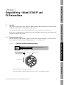
Output Wiring – Model 2700 FF and
PA Transmitters . . . . . . . . . . . . . . . . . . . . . . . . . . . . . . . . . . . . . 53
7.1
7.2
7.3
Overview . . . . . . . . . . . . . . . . . . . . . . . . . . . . . . . . . . . . . . . . . . . . . . . . . . . . . . . . . . 53
FOUNDATION fieldbus wiring. . . . . . . . . . . . . . . . . . . . . . . . . . . . . . . . . . . . . . . . . . . . 53
Profibus-PA wiring. . . . . . . . . . . . . . . . . . . . . . . . . . . . . . . . . . . . . . . . . . . . . . . . . . . 54
Appendix A Specifications . . . . . . . . . . . . . . . . . . . . . . . . . . . . . . . . . . . . . . 55
A.1
A.2
A.3
A.4
Functional specifications. . . . . . . . . . . . . . . . . . . . . . . . . . . . . . . . . . . . . . . . . . . . . .
A.1.1
Electrical connections . . . . . . . . . . . . . . . . . . . . . . . . . . . . . . . . . . . . . . .
A.1.2
Input/output signals . . . . . . . . . . . . . . . . . . . . . . . . . . . . . . . . . . . . . . . . .
A.1.3
Digital communication . . . . . . . . . . . . . . . . . . . . . . . . . . . . . . . . . . . . . . .
A.1.4
Power supply . . . . . . . . . . . . . . . . . . . . . . . . . . . . . . . . . . . . . . . . . . . . . .
A.1.5
Environmental requirements . . . . . . . . . . . . . . . . . . . . . . . . . . . . . . . . . .
A.1.6
Ambient temperature effect . . . . . . . . . . . . . . . . . . . . . . . . . . . . . . . . . . .
A.1.7
EMC compliance . . . . . . . . . . . . . . . . . . . . . . . . . . . . . . . . . . . . . . . . . . .
Hazardous area classifications . . . . . . . . . . . . . . . . . . . . . . . . . . . . . . . . . . . . . . . . .
A.2.1
UL and CSA. . . . . . . . . . . . . . . . . . . . . . . . . . . . . . . . . . . . . . . . . . . . . . .
A.2.2
ATEX and IECEx . . . . . . . . . . . . . . . . . . . . . . . . . . . . . . . . . . . . . . . . . . .
Performance specifications . . . . . . . . . . . . . . . . . . . . . . . . . . . . . . . . . . . . . . . . . . . .
Physical specifications . . . . . . . . . . . . . . . . . . . . . . . . . . . . . . . . . . . . . . . . . . . . . . .
A.4.1
Housing . . . . . . . . . . . . . . . . . . . . . . . . . . . . . . . . . . . . . . . . . . . . . . . . . .
A.4.2
Mounting . . . . . . . . . . . . . . . . . . . . . . . . . . . . . . . . . . . . . . . . . . . . . . . . .
A.4.3
Interface/display. . . . . . . . . . . . . . . . . . . . . . . . . . . . . . . . . . . . . . . . . . . .
A.4.4
Weight . . . . . . . . . . . . . . . . . . . . . . . . . . . . . . . . . . . . . . . . . . . . . . . . . . .
A.4.5
Dimensions . . . . . . . . . . . . . . . . . . . . . . . . . . . . . . . . . . . . . . . . . . . . . . .
55
55
56
61
61
62
62
62
62
62
63
63
64
64
64
65
65
65
Index . . . . . . . . . . . . . . . . . . . . . . . . . . . . . . . . . . . . . . . . . . . . . . . . . . . . . 71
iv
Transmitter Installation: Model 1700 and 2700 Transmitters
1.1
Before You Begin
Chapter 1
Before You Begin
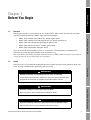
Overview
This chapter provides an orientation to the use of this manual. This manual describes the procedures
required to install the following Model 1700 and 2700 transmitters:
Model 1700 or Model 2700 with analog outputs option board
•
Model 1700 or Model 2700 with intrinsically safe outputs option board
•
Model 2700 with configurable input/outputs option board
•
Model 2700 with FOUNDATION™ fieldbus option board
•
Model 2700 with Profibus-PA option board
Installing the Transmitter
•
If you do not know what transmitter you have, see Section 1.4 for instructions on identifying the
transmitter type from the model number on the transmitter’s tag.
Note: Installation information for Model 1500 transmitters or Model 2500 transmitters is provided in
a separate manual. See the manual for your transmitter.
1.2
Safety
Safety messages are provided throughout this manual to protect personnel and equipment. Read each
safety message carefully before proceeding to the next step.
Sensor Wiring
WARNING
Improper installation in a hazardous area can cause an explosion.
For information about hazardous applications, refer to the approval documentation,
shipped with the transmitter or available from the Micro Motion web site.
WARNING
Output Wiring – AN Transmitters
Hazardous voltage can cause severe injury or death.
Make sure power is disconnected before installing transmitter.
CAUTION
Improper installation could cause measurement error or flowmeter failure.
Follow all instructions to ensure transmitter will operate correctly.
Transmitter Installation: Model 1700 and 2700 Transmitters
1
Before You Begin
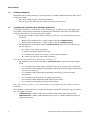
1.3
Flowmeter components
The Model 1700 or 2700 transmitter is one component in your Micro Motion flowmeter. Other major
components include:
1.4
•
The sensor, which provides measurement functions
•
The core processor, which provides memory and processing functions
Transmitter type, installation type, and outputs option board
To install the transmitter, you must know your transmitter type, installation type, and outputs option
board. This section provides information on obtaining this information. The codes described below
match the codes that were used to order your transmitter.
1. Obtain the transmitter's model number, which is provided on a tag attached to the side of the
transmitter.
•
Model 1700 transmitters have a model number of the form 1700xxxxxxxxxx.
•
Model 2700 transmitters have a model number of the form 2700xxxxxxxxxx.
2. The fifth character in the model number (xxxxXxxxxxxxxx) represents the installation type
that was ordered:
•
R = remote (4-wire remote installation)
•
I = integral (transmitter mounted on sensor)
•
C = transmitter/core processor assembly (9-wire remote installation)
•
B = remote core processor with remote transmitter
Note: For more information on installation type, see Figure 2-1.
3. The eighth character in the model number (xxxxxxxXxxxxxx) represents the outputs option
board.
•
A = transmitter with analog outputs option board (one mA, one frequency, one RS-485)
•
B = transmitter with configurable input/outputs option board, default output configuration
(two mA, one frequency)
•
C = transmitter with configurable input/outputs option board, customized output
configuration
•
D = transmitter with intrinsically safe outputs option board
•
E = transmitter with Foundation fieldbus outputs option board
•
G = transmitter with Profibus-PA outputs option board
Note: The remaining characters in the model number describe options that do not affect transmitter
installation.
The following examples illustrate use of the model number to determine transmitter type, installation
type, and output board type:
2
•
1700RxxAxxxxxx = Model 1700 remote transmitter with analog outputs option board
•
2700CxxDxxxxxx = Model 2700 transmitter/core processor assembly with intrinsically safe
outputs option board
Transmitter Installation: Model 1700 and 2700 Transmitters
Before You Begin
1.5
Abbreviations used in this manual
1.6
•
AN = transmitters with the analog outputs option board
•
IS = transmitters with the intrinsically safe outputs option board
•
CIO = transmitters with the configurable input/outputs option board
•
FF = transmitters with the FOUNDATION fieldbus option board
•
PA = transmitters with the Profibus-PA option board
Before You Begin
In this manual:
Transmitter installation procedures
To install the transmitter, the following procedures are required:
Install the transmitter – see Chapter 2
•
Wire the transmitter to the sensor – see Chapter 3
•
Wire the transmitter outputs:
-
For Model 1700 or 2700 AN transmitters, see Chapter 4.
-
For Model 1700 or 2700 IS transmitters, see Chapter 5.
-
For Model 2700 CIO transmitters, see Chapter 6.
-
For Model 2700 FF and PA transmitters, see Chapter 7.
Installing the Transmitter
1.7
•
Flowmeter documentation
Table 1-1 lists documentation sources for other required information. Documents can be obtained in
PDF form from the Micro Motion web site (www.micromotion.com).
Table 1-1
Flowmeter documentation resources
Document
Sensor installation
Installation manual shipped with sensor
Core processor installation (if mounted
remotely from sensor and transmitter)
This document
Transmitter configuration, transmitter
startup and use, and transmitter
troubleshooting
Series 1000 and 2000 Transmitter Configuration and
Use Manual
or
Model 2700 Transmitter with Foundation Fieldbus
Installation and Operation Manual
or
Model 2700 Transmitter with Profibus-PA Installation
and Operation Manual
Sensor Wiring
Topic
Output Wiring – AN Transmitters
Transmitter Installation: Model 1700 and 2700 Transmitters
3
Before You Begin
1.8
Micro Motion customer service
For customer service, phone the support center nearest you:
4
•
In the U.S.A., phone 1-800-522-MASS (1-800-522-6277)
•
In Canada and Latin America, phone (303) 527-5200
•
In Asia, phone (65) 6770-8155
•
In the U.K., phone 0800 - 966 180 (toll-free)
•
Outside the U.K., phone +31 (0) 318 495 670
Transmitter Installation: Model 1700 and 2700 Transmitters
2.1
Before You Begin
Chapter 2
Installing the Transmitter
Overview
This chapter describes how to install Micro Motion Model 1700 and 2700 transmitters. The following
general steps are required:
Determine the location of the transmitter and other flowmeter components (see Section 2.3)
•
Mount the transmitter (see Section 2.4)
•
Mount the core processor, if required (see Section 2.5)
•
Ground the flowmeter components (see Section 2.6)
•
Supply power to the flowmeter (see Section 2.7)
•
Rotate the display, if desired and the transmitter has a display (see Section 2.8)
Installing the Transmitter
2.2
•
Installation architecture
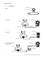
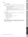
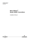
Your flowmeter installation will match one of the architectures shown in Figure 2-1. Mounting, sensor
wiring, and grounding requirements depend on this architecture. Your installation type should be
consistent with the installation type specified in your transmitter model number (see Section 1.4).
Sensor Wiring
Output Wiring – AN Transmitters
Transmitter Installation: Model 1700 and 2700 Transmitters
5
Installing the Transmitter
Figure 2-1
Installation types
Transmitter
Integral
Core processor
Sensor
4-wire remote
Transmitter
Sensor
4-wire cable
Core processor
Transmitter
9-wire remote
Sensor
Core
processor
9-wire cable
Junction box
Transmitter
Remote core processor with
remote transmitter
4-wire cable
Sensor
Core
processor
Junction box
6
9-wire cable
Transmitter Installation: Model 1700 and 2700 Transmitters
Installing the Transmitter
2.3
Determining an appropriate location
2.3.1
Before You Begin
To determine an appropriate location for the transmitter, you must consider the environmental
requirements of the transmitter and core processor, hazardous area classification, location of power
source, cable lengths, accessibility for maintenance, and visibility of the display (if the transmitter is
equipped with a display).
Environmental requirements
The transmitter’s environmental requirements include temperature, humidity, and vibration.
Temperature limits
Installing the Transmitter
Install the transmitter in an environment where ambient temperature is between –40 and +140 °F
(–40 and +60 °C). If possible, install the transmitter in a location that will prevent direct exposure to
sunlight.
Different ambient temperature requirements may apply when installing the transmitter in a hazardous
area. Refer to the approval documentation shipped with the transmitter or available on the Micro
Motion web site.
Humidity limits
Install the transmitter in an environment where relative humidity is between 5 and 95%,
non-condensing at 140 °F (60 °C).
Vibration limits
The transmitter meets IEC 68.2.6, endurance sweep, 5 to 2000 Hz, 50 sweep cycles at 1.0 g.
2.3.2
Hazardous area classifications
If you plan to mount the transmitter in a hazardous area:
Verify that the transmitter has the appropriate hazardous area approval. Each transmitter has a
hazardous area approval tag attached to the transmitter housing.
•
Ensure that any cable used between the transmitter and the sensor meets the hazardous area
requirements.
For more information about hazardous area classifications and requirements, see Section A.2.
2.3.3
Sensor Wiring
•
Power source
Connect the transmitter to an AC or DC voltage source. The transmitter automatically recognizes the
source voltage.
Output Wiring – AN Transmitters
AC power requirements
If you are using AC power, the following requirements apply:
•
85–265 VAC
•
50/60 Hz
•
6 watts typical, 11 watts maximum
Transmitter Installation: Model 1700 and 2700 Transmitters
7
Installing the Transmitter
DC power requirements
Note: These requirements assume a single transmitter per cable. Connecting multiple transmitters to
a single cable should be avoided.
If you are using DC power, the following requirements apply:
•
18–100 VDC
•
6 watts typical, 11 watts maximum
•
At startup, the transmitter power source must provide a minimum of 1.5 amps of short-term
current per transmitter.
•
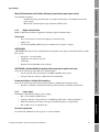
Length and conductor diameter of the power cable must be sized to provide 18 VDC minimum
at the power terminals, at a load current of 0.5 amps. To size the cable, refer to Table 2-1 and
use the following formula as a guideline:
MinimumSupplyVoltage = 18V + ( CableResistance × CableLength × 0.5 A )
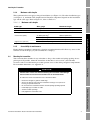
Table 2-1
Typical power cable resistances at 68 °F (20 °C)
Gauge
Resistance(1)
14 AWG
0.0050 Ω/foot
16 AWG
0.0080 Ω/foot
18 AWG
0.0128 Ω/foot
20 AWG
0.0204 Ω/foot
2,5 mm
2
0,0136 Ω/meter
1,5 mm
2
0,0228 Ω/meter
1 mm
0,0340 Ω/meter
2
0,75 mm
0,5 mm
2
2
0,0460 Ω/meter
0,0680 Ω/meter
(1) These values include the resistance of both high and low conductors in a cable.
Example
The transmitter is mounted 350 feet from a DC power supply. If you want to use
16 AWG cable, calculate the required voltage at the DC power supply as follows:
MinimumSupplyVoltage = 18V + ( CableResistance × CableLength × 0.5A )
MinimumSupplyVoltage = 18V + ( 0.0080 ohms/ft × 350 ft × 0.5A )
MinimumSupplyVoltage = 19.4V
8
Transmitter Installation: Model 1700 and 2700 Transmitters
Installing the Transmitter
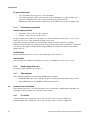
2.3.4
Maximum cable lengths
Table 2-2
Before You Begin
This requirement does not apply to integral installations (see Figure 2-1). For other installation types
(see Figure 2-1), maximum cable length between flowmeter components depends on the installation
type and the cable type. Refer to Figure 2-1, then see Table 2-2.
Maximum cable lengths
Cable type
Wire gauge
Maximum length
Micro Motion 9-wire
Not applicable
60 feet (20 meters)
Micro Motion 4-wire
Not applicable
1000 feet (300 meters)
User-supplied 4-wire
• Power wires (VDC)
22 AWG (0,35 mm2)
2
20 AWG (0,5 mm )
• Signal wires (RS-485)
2.3.5
500 feet (150 meters)
18 AWG (0,8 mm )
1000 feet (300 meters)
22 AWG (0,35 mm2) or larger
1000 feet (300 meters)
Installing the Transmitter
2
300 feet (90 meters)
Accessibility for maintenance
Ensure that the transmitter is mounted in a location and orientation that will allow easy access to the
terminals and to the display (if your transmitter has a display).
2.4
Mounting the transmitter
You can mount the transmitter in any orientation as long as the conduit and wiring openings do not
point upward. If possible, mount the transmitter so that there is at least 8–10″ (200–250 mm)
clearance at the rear of the housing to enable operator access to the wiring and power compartments.
For transmitter dimensions, see Appendix A.
Sensor Wiring
CAUTION
Condensation or excessive moisture entering the transmitter could damage
the transmitter and result in measurement error or flowmeter failure.
To reduce the risk of measurement error or flowmeter failure:
•
•
Transmitter Installation: Model 1700 and 2700 Transmitters
Output Wiring – AN Transmitters
•
•
•
•
Ensure the integrity of gaskets and O-rings.
Grease the O-rings every time the transmitter housing or core processor
housing is opened and closed.
Do not mount the transmitter with the conduit openings pointing upward.
Install drip legs on conduit or cable.
Seal the conduit openings.
Fully tighten the transmitter cover.
9
Installing the Transmitter
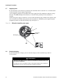
2.4.1
Integral installations
If you chose an integral installation (see Figure 2-1), there are no special mounting instructions for the
transmitter.
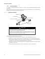
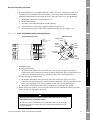
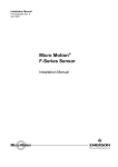
You can rotate an integrally mounted transmitter up to 360° in 90° increments, to one of four possible
positions on the core processor base. See Figure 2-2.
Figure 2-2
Rotating the transmitter
Transmitter
Transition ring
Core processor
4 X Cap screws (4 mm)
Base
Sensor
CAUTION
Damaging the wires that connect the transmitter to the core processor can
cause measurement error or flowmeter failure.
To reduce the risk of damaging the wires, do not move the transmitter more than a
few inches from the core processor. When reassembling the flowmeter, ensure that
the wires will not be bent or pinched in the housing.
To rotate the transmitter on the core processor:
1. Loosen each of the four cap screws (4 mm) that fasten the transmitter to the base.
2. Rotate the transmitter counter-clockwise so that the cap screws are in the unlocked position.
3. Gently lift the transmitter straight up, disengaging it from the cap screws. Do not disconnect or
damage the wires that connect the transmitter to the core processor.
4. Rotate the transmitter to the desired orientation, and align the slots with the cap screws. Do not
pinch or stress the wires.
5. Gently lower the transmitter onto the base, inserting the cap screws into the slots.
10
Transmitter Installation: Model 1700 and 2700 Transmitters
Installing the Transmitter
6. Rotate the transmitter clockwise so that the cap screws are in the locked position.
Before You Begin
7. Tighten the cap screws, torquing to 20 to 30 in-lbs (2,3 to 3,4 N-m).
CAUTION
Twisting the core processor will damage the sensor.
To reduce the risk of damaging the sensor, do not allow the core processor
to rotate.
2.4.2
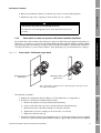
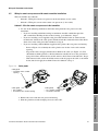
4-wire remote or remote core processor with remote transmitter installations
Figure 2-3
4-wire remote – Wall mount or pipe mount
Sensor Wiring
Mounting bracket
(wall mount)
Installing the Transmitter
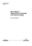
If you chose the 4-wire remote or the remote core processor with remote transmitter installation (see
Figure 2-1), see Figure 2-3 for a diagram of the mounting bracket supplied with the transmitter. Both
pipe mounting and wall mounting are shown. Ensure that the transmitter is mounted and oriented in a
way that will allow easy access to the terminals and to the display (if your transmitter has a display).
Mounting bracket
(pipe mount)
Note: If possible, maintain 8–10″ (200–250 mm) clearance at the
rear of the transmitter.
To mount the transmitter:
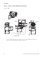
1. Identify the components shown in Figure 2-4. For dimensions, see Appendix A.
a. Remove the junction end-cap from the junction housing.
b. Loosen each of the four cap screws (4 mm) inside the junction housing.
c. Rotate the bracket so that the transmitter is oriented as desired.
d. Tighten the cap screws, torquing to 30 to 38 in-lbs (3 to 4 N-m).
e. Replace the junction end-cap.
3. Attach the mounting bracket to an instrument pole or wall. For pipe mount, two user-supplied
U-bolts are required. Contact Micro Motion to obtain a pipe-mount installation kit if required.
Transmitter Installation: Model 1700 and 2700 Transmitters
11
Output Wiring – AN Transmitters
2. If desired, re-orient the transmitter on the bracket.
Installing the Transmitter
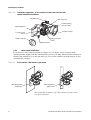
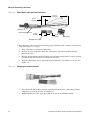
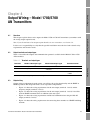
Figure 2-4
Transmitter components – 4-wire remote or remote core processor with
remote transmitter installations
Ground screw
Main enclosure
Conduit opening
for 4-wire cable
Mounting bracket
Junction housing
4 X Cap screws
(4 mm)
Junction end-cap
Mating connector
socket
Mating connector
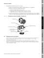
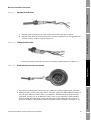
2.4.3
9-wire remote installations
If you chose a 9-wire remote installation (see Figure 2-1), see Figure 2-5 for a diagram of the
mounting bracket supplied with the transmitter/core processor assembly. Ensure that the transmitter is
mounted and oriented in a way that will allow easy access to the terminals and to the display (if your
transmitter has a display).
Figure 2-5
9-wire remote – Wall mount or pipe mount
Mounting bracket
(wall mount)
Mounting bracket
(pipe mount)
Note: If possible, maintain 8–10″ (200–250 mm) clearance at the
rear of the transmitter.
12
Transmitter Installation: Model 1700 and 2700 Transmitters
Installing the Transmitter
To mount the transmitter/core processor assembly:
Before You Begin
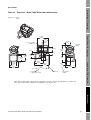
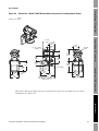
1. Identify the components shown in Figure 2-6. For dimensions, see Appendix A.
2. If desired, re-orient the transmitter on the bracket.
a. Loosen each of the four cap screws (4 mm).
b. Rotate the bracket so that the transmitter is oriented as desired.
c. Tighten the cap screws, torquing to 30 to 38 in-lbs (3 to 4 N-m).
3. Attach the mounting bracket to an instrument pole or wall. For pipe mount, two user-supplied
U-bolts are required. Contact Micro Motion to obtain a pipe-mount installation kit if required.
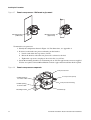
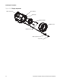
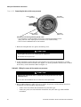
Figure 2-6
Transmitter/core processor assembly – Exploded view
Installing the Transmitter
Transmitter
Core processor
4 × Cap screws (4 mm)
Core processor housing
Conduit opening
for 9-wire cable
End-cap
Mounting bracket
Sensor Wiring
2.5
Mounting the remote core processor
Note: This step is required only for remote core processor with remote transmitter installations (see
Figure 2-1). If you have an integral installation, 4-wire remote installation, or 9-wire remote
installation, go to Section 2.6.
Transmitter Installation: Model 1700 and 2700 Transmitters
Output Wiring – AN Transmitters
If you chose the remote core processor with remote transmitter installation (see Figure 2-1), see
Figure 2-3 for a diagram of the mounting bracket supplied with the transmitter. Both pipe mounting
and wall mounting are shown.
13
Installing the Transmitter
Figure 2-7
Remote core processor – Wall mount or pipe mount
Mounting bracket
(wall mount)
Mounting bracket
(pipe mount)
To mount the core processor:
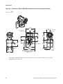
1. Identify the components shown in Figure 2-8. For dimensions, see Appendix A.
2. If desired, reorient the core processor housing on the bracket.
a. Loosen each of the four cap screws (4 mm).
b. Rotate the bracket so that the core processor is oriented as desired.
c. Tighten the cap screws, torquing to 30 to 38 in-lbs (3 to 4 N-m).
3. Attach the mounting bracket to an instrument pole or wall. For pipe mount, two user-supplied
U-bolts are required. Contact Micro Motion to obtain a pipe-mount installation kit if required.
Figure 2-8
Remote core processor components
Core processor lid
Conduit opening
for 4-wire cable
Conduit opening
for 9-wire cable
Mounting bracket
14
4 × Cap screws (4 mm)
Core processor housing
End-cap
Transmitter Installation: Model 1700 and 2700 Transmitters
Installing the Transmitter
2.6
Grounding the flowmeter components
Before You Begin
Grounding requirements depend on the installation type (see Figure 2-1). Grounding methods for
each flowmeter component are listed in Table 2-3.
CAUTION
Improper grounding could cause measurement error.
To reduce the risk of measurement error:
•
•
Installing the Transmitter
•
Ground the transmitter to earth, or follow ground network requirements for the
facility.
For installation in an area that requires intrinsic safety, refer to Micro Motion
approval documentation, shipped with the transmitter or available from the Micro
Motion web site.
For hazardous area installations in Europe, refer to standard EN 60079-14 if
national standards do not apply.
If national standards are not in effect, follow these grounding guidelines:
Table 2-3
•
Use copper wire, 14 AWG (2,5 mm2 ) or larger wire size, for grounding.
•
Keep all ground leads as short as possible, less than 1 Ω impedance.
•
Connect ground leads directly to earth, or follow plant standards.
Grounding methods for flowmeter components
Installation
architecture
Grounding method
Integral
Sensor / core processor /
transmitter
Ground via piping, if possible (see sensor documentation). Otherwise,
ground according to applicable local standards using either the
transmitter’s internal or external ground screw.
4-wire remote
Sensor / core processor
assembly
See sensor documentation.
Transmitter
Ground according to applicable local standards, using either the
transmitter’s internal or external ground screw.
Sensor / junction box
See sensor documentation.
Transmitter / core
processor assembly
Ground according to applicable local standards, using either the
transmitter’s internal or external ground screw, or the core processor’s
internal ground screw.
Sensor
See sensor documentation.
Core processor
Ground according to applicable local standards, using either the internal
or external ground screw.
Transmitter
Ground according to applicable local standards, using either the
transmitter’s internal or external ground screw.
9-wire remote
Transmitter Installation: Model 1700 and 2700 Transmitters
15
Output Wiring – AN Transmitters
Remote core
processor with
remote
transmitter
Sensor Wiring
Components
Installing the Transmitter
2.7
Supplying power
In all installations, power must be provided to the transmitter. Refer to Section 2.3.3 for information
on the transmitter’s power supply requirements.
A user-supplied switch may be installed in the power supply line. For compliance with low-voltage
directive 73/23/EEC (European installations), a switch in close proximity to the transmitter is
required.
Connect the power supply to terminals 9 and 10, under the Warning flap. Terminate the positive (line)
wire on terminal 10 and the return (neutral) wire on terminal 9. Ground the power supply using the
equipment ground, also under the Warning flap. See Figure 2-9.
Figure 2-9
Wiring the transmitter power supply
9
10
Equipment
ground
Warning flap
2.8
Rotating the display
If your transmitter has a display, you can rotate the display on the transmitter up to 360° in
90° increments.
WARNING
Removing the display cover in explosive atmospheres while the power is on
can cause an explosion.
To reduce the risk of an explosion, before removing the display cover in explosive
atmospheres, be sure to shut off the power and wait five minutes.
16
Transmitter Installation: Model 1700 and 2700 Transmitters
Installing the Transmitter
Before You Begin
WARNING
Using a dry cloth to clean the display cover can cause static discharge,
which could result in an explosion in an explosive atmosphere.
To reduce the risk of an explosion, always use a damp cloth to clean the display
cover in an explosive atmosphere.
To rotate the display, follow the instructions below:
1. Power down the transmitter.
2. Remove the end-cap clamp by removing the cap screw. See Figure 2-10.
3. Turn the display cover counterclockwise to remove it from the main enclosure.
5. Carefully pull the display module out of the main enclosure until the sub-bezel pin terminals
are disengaged from the display module.
Note: The display pins may come out of the board stack with the display module. If this happens,
simply remove the pins and reinstall them.
6. Rotate the display module to the desired position.
7. Insert the sub-bezel pin terminals into the display module pin holes to secure the display in its
new position.
Installing the Transmitter
4. Carefully loosen (and remove if necessary) the semicaptive display screws while holding the
display module in place.
8. If you have removed the display screws, line them up with the matching holes on the
sub-bezel, then reinsert and tighten them.
9. Place the display cover onto the main enclosure. Turn the display cover clockwise until it is
snug.
10. Replace the end-cap clamp by reinserting and tightening the cap screw.
Sensor Wiring
11. Restore power to the transmitter.
Output Wiring – AN Transmitters
Transmitter Installation: Model 1700 and 2700 Transmitters
17
Installing the Transmitter
Figure 2-10 Display components
Main enclosure
Pin terminals
Sub-bezel
Display module
Display cover
Display screws
End-cap clamp
Cap screw
18
Transmitter Installation: Model 1700 and 2700 Transmitters
3.1
Before You Begin
Chapter 3
Wiring the Transmitter to the Sensor
Overview
This chapter describes how to connect Micro Motion Model 1700 and 2700 transmitters to a Micro
Motion sensor.
Wiring requirements between the sensor and transmitter depend on the installation type (see
Figure 2-1).
•
If you have a 4-wire remote transmitter installation, review the information on 4-wire cable in
Section 3.2, then follow the instructions in Section 3.3.
•
If you have a 9-wire remote transmitter installation, review the information on 9-wire cable in
Section 3.2, then follow the instructions in Section 3.4.
•
If you have a remote core processor with remote transmitter installation, review the
information on both 4-wire and 9-wire cable in Section 3.2, then follow the instructions in
Section 3.5.
Installing the Transmitter
Note: If you have an integral installation, this step is not required. Continue with wiring the
transmitter outputs (Chapters 4–7).
CAUTION
Sensor Wiring
Large electromagnetic fields can interfere with flowmeter communication
signals.
Improper installation of cable or conduit can cause measurement error or flowmeter
failure. To reduce the risk of measurement error or flowmeter failure, keep cable or
conduit away from devices such as transformers, motors, and power lines which
produce large electromagnetic fields.
3.2
Cable types
This section describes the types of 4-wire cable and 9-wire cable that can be used for wiring the
transmitter to the sensor.
Output Wiring – AN Transmitters
Transmitter Installation: Model 1700 and 2700 Transmitters
19
Wiring the Transmitter to the Sensor
3.2.1
4-wire cable
Micro Motion offers two types of 4-wire cable: shielded and armored. Both types contain shield
drain wires.
User-supplied 4-wire cable must meet the following requirements:
•
Twisted pair construction
•
The gauge requirements as described in Table 2-2
•
The applicable hazardous area requirements, if the core processor is installed in a hazardous
area (see the approval documentation shipped with the transmitter or available on the Micro
Motion web site)
3.2.2
9-wire cable
Micro Motion offers three types of 9-wire cable: jacketed, shielded, and armored. Refer to Micro
Motion’s 9-Wire Flowmeter Cable Preparation and Installation Guide for detailed descriptions of
these cable types and for assistance in selecting the appropriate cable for your installation.
3.3
Wiring for 4-wire remote installations
To connect the cable, follow the steps below.
1. Prepare the cable as described in the sensor documentation.
2. Connect the cable to the core processor as described in the sensor documentation.
3. To connect the cable to the transmitter:
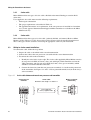
a. Identify the wires in the 4-wire cable. The 4-wire cable supplied by Micro Motion consists
of one pair of 18 AWG (0,75 mm2) wires (red and black), which should be used for the
VDC connection, and one pair of 22 AWG (0,35 mm2) wires (green and white), which
should be used for the RS-485 connection.
b. Connect the four wires from the core processor to terminals 1–4 on the mating connector
of the transmitter. See Figures 3-1 and 3-2. Never ground the shield, braid, or drain wire(s)
at the transmitter.
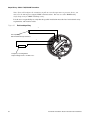
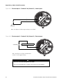
Figure 3-1
4-wire cable between enhanced core processor and transmitter
Core processor
terminals
4-wire cable
Maximum cable length: see Table 2-2
20
VDC+
VDC–
RS-485A
RS-485B
RS-485B (Green)
RS-485A (white)
VDC+ (Red)
VDC– (Black)
User-supplied or
factory-supplied cable
Mating connector
(transmitter)
Transmitter Installation: Model 1700 and 2700 Transmitters
Wiring the Transmitter to the Sensor
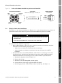
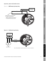
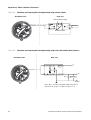
Figure 3-2
4-wire cable between standard core processor and transmitter
RS-485B
(Green)
VDC+
(Red)
4-wire cable
Maximum cable length: see Table 2-2
User-supplied or
factory-supplied cable
VDC–
(Black)
Mating connector
(transmitter)
VDC+
VDC–
RS-485A
RS-485B
RS-485A
(White)
Wiring for 9-wire remote installations
If you chose a 9-wire remote installation (see Figure 2-1), a 9-wire cable must be used to connect the
junction box on the sensor to the core processor on the transmitter/core processor assembly.
CAUTION
Allowing the shield drain wires to contact the sensor junction box can cause
flowmeter errors.
Installing the Transmitter
3.4
Before You Begin
Core processor terminals
Do not allow the shield drain wires to contact the sensor junction box.
To connect the cable, follow the steps below:
•
At the sensor end, follow the instructions for your cable type.
•
At the transmitter end, follow the instructions for your cable type with an MVD
transmitter.
Sensor Wiring
1. Refer to Micro Motion’s 9-Wire Flowmeter Cable Preparation and Installation Guide for
instructions on cable shielding and preparation:
2. To connect the wires, refer to Micro Motion’s 9-Wire Flowmeter Cable Preparation and
Installation Guide and follow the instructions for your sensor with an MVD transmitter.
Additional information for connecting the wires at the transmitter is provided below:
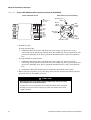
a. Identify the components shown in Figure 2-6.
b. Remove the end-cap.
c. Insert the 9-wire cable through the conduit opening.
Output Wiring – AN Transmitters
d. Connect the wires to the plugs supplied with the transmitter.
e. Insert the plugs into the sockets inside the lower conduit ring. See Figure 3-3.
Transmitter Installation: Model 1700 and 2700 Transmitters
21
Wiring the Transmitter to the Sensor
Figure 3-3
9-wire cable between sensor and core processor (on transmitter)
9-wire cable from sensor
Core processor (on transmitter)
Black
(Drains from all
wire sets)
Ground screw
Black
Brown
Violet
Yellow
Brown
Red
Red
Green
White
Green
White
Plug and
socket
Blue
Gray
Orange
Violet
Yellow
Mounting screw
Blue
Gray
Orange
3. Ground the cable.
If using jacketed cable:
a. Ground the shield drain wires (the black wire) only on the core processor end, by
connecting it to the ground screw inside the lower conduit ring. Never ground to the core
processor’s mounting screw. Never ground the shield drain wires at the sensor junction
box.
If using shielded or armored cable:
a. Ground the shield drain wires (the black wire) only on the core processor end, by
connecting it to the ground screw inside the lower conduit ring. Never ground to the core
processor’s mounting screw. Never ground the shield drain wires at the sensor junction
box.
b. Ground the cable braid on both ends, by terminating it inside the cable glands.
4. Ensure integrity of gaskets, grease all O-rings, then close the junction box housing and core
processor end-cap, and tighten all screws.
CAUTION
Damaging the wires that connect the transmitter to the sensor can cause
measurement error or flowmeter failure.
To reduce the risk of measurement error or flowmeter failure, when closing the
housings on the sensor and core processor, make sure that the wires are not
caught or pinched.
22
Transmitter Installation: Model 1700 and 2700 Transmitters
Wiring the Transmitter to the Sensor
3.5
Wiring for remote core processor with remote transmitter installations
•
Subtask 1: Wiring the remote core processor to the transmitter (4-wire cable)
•
Subtask 2: Wiring the sensor to the remote core processor (9-wire cable)
Before You Begin
This task includes two subtasks:
Subtask 1: Wire the remote core processor to the transmitter
1. Use one of the following methods to shield the wiring from the core processor to the
transmitter:
If you are installing unshielded wiring in continuous metallic conduit that provides
360° termination shielding for the enclosed wiring, go to Subtask 1, Step 6.
•
If you are installing a user-supplied cable gland with shielded cable or armored cable,
terminate the shields in the cable gland. Terminate both the armored braid and the shield
drain wires in the cable gland. Go to Subtask 1, Step 6.
•
If you are installing a Micro Motion-supplied cable gland at the core processor housing:
-
Refer to Figure 3-4 to identify the cable gland to use for the 4-wire cable conduit
opening.
-
Prepare the cable and apply shielded heat shrink to the cable (see Figure 3-5). The
shielded heat shrink provides a shield termination suitable for use in the gland when
using cable whose shield consists of foil and not a braid. Proceed to Subtask 1, Step 2.
-
With armored cable, where the shield consists of braid, prepare the cable as described
below, but do not apply heat shrink. Proceed to Subtask 1, Step 2.
Installing the Transmitter
Figure 3-4
•
Cable glands
Cable gland
• Used with 4-wire conduit
opening
Sensor Wiring
Cable gland
• 3/4″–14 NPT
• Used with 9-wire conduit opening
Cable glands
• 1/2″–14 NPT or M20 × 1.5
• Used with transmitter
Output Wiring – AN Transmitters
2. Remove the cover from the core processor housing.
3. Slide the gland nut and the clamping insert over the cable.
Transmitter Installation: Model 1700 and 2700 Transmitters
23
Wiring the Transmitter to the Sensor
Figure 3-5
Micro Motion cable gland and heat shrink
4 1/2 in
(114 mm)
3/4 in
(19 mm)
Gland nut
Gland clamping insert
7/8 in
(22 mm)
7/8 in
(22 mm)
Gland body
Shielded heat shrink
4. For connection at the core processor housing, prepare shielded cable as follows (for armored
cable, omit steps d, e, f, and g):
a. Strip 4 1/2 inches (114 mm) of cable jacket.
b. Remove the clear wrap that is inside the cable jacket, and remove the filler material
between the wires.
c. Remove the foil shield or braid and drain wires from the insulated wires, leaving 3/4 inch
(19 mm) of foil or braid exposed, and separate the wires.
d. Wrap the shield drain wire(s) around the exposed foil twice. Cut off the excess wire. See
Figure 3-6.
Figure 3-6
Wrapping the shield drain wires
e. Place the shielded heat shrink over the exposed shield drain wire(s). The tubing should
completely cover the drain wires. See Figure 3-7.
f.
24
Without burning the cable, apply heat (250 °F or 120 °C) to shrink the tubing.
Transmitter Installation: Model 1700 and 2700 Transmitters
Wiring the Transmitter to the Sensor
Figure 3-7
Applying the heat shrink
Before You Begin
g. Position gland clamping insert so the interior end is flush with the heat shrink.
Figure 3-8
Folding the cloth shield
i.
Figure 3-9
Installing the Transmitter
h. Fold the cloth shield or braid and drain wires over the clamping insert and approximately
1/8 inch (3 mm) past the O-ring. See Figure 3-8.
Install the gland body into the core processor housing conduit opening. See Figure 3-9.
Gland body and core processor housing
Sensor Wiring
6. Identify the wires in the 4-wire cable. The 4-wire cable supplied by Micro Motion consists of
one pair of 18 AWG (0,75 mm2) wires (red and black), which should be used for the VDC
connection, and one pair of 22 AWG (0,35 mm2) wires (green and white), which should be
used for the RS-485 connection. Connect the four wires to the numbered slots on the core
processor, matching corresponding numbered terminals on the transmitter. See Figure 3-10.
Transmitter Installation: Model 1700 and 2700 Transmitters
25
Output Wiring – AN Transmitters
5. Insert the wires through the gland body and assemble the gland by tightening the gland nut.
Wiring the Transmitter to the Sensor
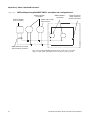
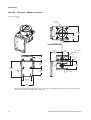
Figure 3-10 Connecting the wires at the core processor
Power supply +
(Red wire)
RS-485B
(Green wire)
Power supply –
(Black wire)
RS-485A
(White wire)
Core processor housing internal ground screw
• For connections to earth ground (if core processor cannot be grounded via sensor
piping and local codes require ground connections to be made internally)
• Do not connect shield drain wires to this terminal
7. Reinstall and tighten the core processor housing cover.
CAUTION
Twisting the core processor will damage the equipment.
Do not twist the core processor.
8. At the transmitter, connect the four wires from the core processor to terminals 1–4 on the
mating connector of the transmitter. See Figure 3-2. Never ground the shield, braid, or shield
drain wire(s) at the transmitter. Refer to Figure 2-4.
Subtask 2: Wiring the sensor to the remote core processor
CAUTION
Allowing the shield drain wires to contact the sensor junction box can cause
flowmeter errors.
Do not allow the shield drain wires to contact the sensor junction box.
1. Refer to Micro Motion’s 9-Wire Flowmeter Cable Preparation and Installation Guide for
instructions on cable shielding and preparation:
26
•
At the sensor end, follow the instructions for your cable type.
•
At the core processor end, follow the instructions for your cable type with an MVD
transmitter.
Transmitter Installation: Model 1700 and 2700 Transmitters
Wiring the Transmitter to the Sensor
Before You Begin
2. To connect the wires, refer to Micro Motion’s 9-Wire Flowmeter Cable Preparation and
Installation Guide and follow the instructions for your sensor with an MVD transmitter.
Additional information for connecting the wires at the core processor is provided below:
a. Identify the components shown in Figure 2-8.
b. Remove the end-cap.
c. Insert the 9-wire cable through the conduit opening.
d. Connect the wires to the plugs supplied with the core processor.
e. Insert the plugs into the sockets inside the lower conduit ring. See Figure 3-11.
Figure 3-11 9-wire cable between sensor and core processor
9-wire cable from sensor
Core processor
Brown
Red
Ground screw
Installing the Transmitter
Black
(Drains from all
wire sets)
Black
Brown
Violet
Yellow
Red
Green
White
Green
White
Blue
Gray
Plug and
socket
Orange
Violet
Yellow
Mounting screw
Blue
Gray
Orange
3. Ground the cable.
a. Ground the shield drain wires (the black wire) only on the core processor end, by
connecting it to the ground screw inside the lower conduit ring. Never ground to the core
processor’s mounting screw. Never ground the cable at the sensor junction box.
If using shielded or armored cable:
Sensor Wiring
If using jacketed cable:
a. Ground the shield drain wires (the black wire) only on the core processor end, by
connecting it to the ground screw inside the lower conduit ring. Never ground to the core
processor’s mounting screw. Never ground the cable at the sensor junction box.
b. Ground the cable braid on both ends, by terminating it inside the cable glands.
Output Wiring – AN Transmitters
4. Ensure integrity of gaskets, grease all O-rings, then close the junction box housing and core
processor end-cap, and tighten all screws.
CAUTION
Damaging the wires that connect the transmitter to the sensor can cause
measurement error or flowmeter failure.
To reduce the risk of measurement error or flowmeter failure, when closing the
housings on the sensor and core processor, make sure that the wires are not
caught or pinched.
Transmitter Installation: Model 1700 and 2700 Transmitters
27
28
Transmitter Installation: Model 1700 and 2700 Transmitters
4.1
Before You Begin
Chapter 4
Output Wiring – Model 1700/2700
AN Transmitters
Overview
Note: If you do not know what outputs option board is in your transmitter, see Section 1.4.
It is the user’s responsibility to verify that the specific installation meets the local and national safety
requirements and electrical codes.
4.2
Output terminals and output types
Installing the Transmitter
This chapter explains how to wire outputs for Model 1700 or 2700 AN transmitters (transmitters with
the analog outputs option board).
Table 4-1 describes the outputs and communication protocols available for the Model 1700 or 2700
AN transmitter.
Table 4-1
Terminals and output types
Terminals
Model 1700 output type
(1)
Model 2700 output type
(1)
Communication
Milliamp/Bell 202
Milliamp/Bell 202
HART
3&4
Frequency
• Frequency (default)
• Discrete
None
5&6
RS-485
RS-485
• Modbus (default)
• HART
Sensor Wiring
1&2
(1) The Bell 202 signal is superimposed on the mA output.
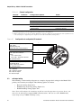
4.3
Output wiring
Output wiring requirements depend on how you will use the analog functionality and the HART or
Modbus protocol. This chapter describes several possible configurations:
Figure 4-1 shows the wiring requirements for the mA output (terminals 1 and 2) and the
frequency output (terminals 3 and 4).
•
Figure 4-2 shows the wiring requirements for the mA output (terminals 1 and 2) if it will be
used for HART communications in addition to the mA signal.
•
Figure 4-3 shows the wiring requirements for RS-485 communications using the RS-485
output (terminals 5 and 6).
•
Figure 4-4 shows the wiring requirements for connecting the transmitter to a HART multidrop
network.
Transmitter Installation: Model 1700 and 2700 Transmitters
29
Output Wiring – AN Transmitters
•
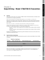
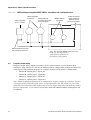
Output Wiring – Model 1700/2700 AN Transmitters
Note: If you will configure the transmitter to poll an external temperature or pressure device, you
must wire the mA output to support HART communications. You may use either HART/analog
single-loop wiring or HART multidrop wiring.
It is the user’s responsibility to verify that the specific installation meets the local and national safety
requirements and electrical codes.
Figure 4-1
Basic analog wiring
+
–
mA output loop
820 Ω maximum loop resistance
+
–
00042
Frequency receiving device
Output voltage level is +24 VDC ± 3%
30
Transmitter Installation: Model 1700 and 2700 Transmitters
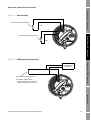
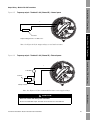
Output Wiring – Model 1700/2700 AN Transmitters
Figure 4-2
HART/analog single-loop wiring
Before You Begin
+
HARTcompatible host
or controller
–
820 Ω maximum loop resistance
For HART communications:
• 600 Ω maximum loop resistance
• 250 Ω minimum loop resistance
Installing the Transmitter
Figure 4-3. RS-485 point-to-point wiring
Primary
controller
Sensor Wiring
Multiplexer
RS-485A
RS-485B
Output Wiring – AN Transmitters
Other devices
Note: The RS-485 communication wires must be shielded.
Transmitter Installation: Model 1700 and 2700 Transmitters
31
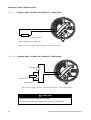
Output Wiring – Model 1700/2700 AN Transmitters
Figure 4-4
HART multidrop wiring with SMART FAMILY™ transmitters and a configuration tool
HART-compatible
transmitters
HART-compatible
host or controller
SMART FAMILY™
transmitters
24 VDC loop power
supply required for
passive transmitters
Model 1700 or 2700
AN transmitter
600 Ω maximum resistance
250 Ω minimum resistance
Note: For optimum HART communication, make sure the output
loop is single-point-grounded to an instrument-grade ground.
32
Transmitter Installation: Model 1700 and 2700 Transmitters
5.1
Overview
Note: If you do not know what outputs option board is in your transmitter, see Section 1.4.
Intrinsically safe outputs require external power. “External power” means that the terminals must be
connected to an independent power supply. The output wiring instructions include power setup and
power wiring.
Note: The term “passive” is sometimes used to describe externally powered outputs.
Output wiring requirements depend on whether the transmitter will be installed in a safe area or a
hazardous area. This chapter describes several possible configurations:
•
Section 5.3 describes wiring requirements for the outputs if the transmitter will be installed in
a safe area.
•
Section 5.4 describes wiring requirements for the outputs if the transmitter will be installed in
a hazardous area.
Output terminals and output types
Table 5-1 describes the outputs and communication protocols available for the Model 1700 or 2700 IS
transmitter.
Table 5-1
Terminals
Terminals and output types
Model 1700 output type
(1)
Model 2700 output type
(1)
Communication
1&2
Milliamp/Bell 202
Milliamp/Bell 202
HART
3&4
Frequency
• Frequency (default)
• Discrete
None
5&6
Not used
Milliamp
None
Output Wiring – FF/PA Transmitters
It is the user’s responsibility to verify that the specific installation meets the local and national safety
requirements and electrical codes.
Output Wiring – CIO Transmitters
This chapter explains how to wire outputs for Model 1700 or 2700 IS transmitters (transmitters with
the intrinsically safe outputs option board).
5.2
Output Wiring – IS Transmitters
Chapter 5
Output Wiring – Model 1700/2700 IS Transmitters
(1) The Bell 202 signal is superimposed on the mA output.
Specifications
Note: If you will configure the transmitter to poll an external temperature or pressure device, you
must wire the mA output to support HART communications. You may use either HART/analog
single-loop wiring or HART multidrop wiring.
Transmitter Installation: Model 1700 and 2700 Transmitters
33
Output Wiring – Model 1700/2700 IS Transmitters
5.3
Safe area output wiring
The following notes and diagrams are designed to be used as a guide for wiring the Model 1700 or
Model 2700 outputs for safe area applications.
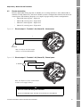
5.3.1
Safe area mA output wiring
The following 4–20 mA wiring diagrams are examples of proper basic wiring for the Model 1700 mA
output or Model 2700 primary and secondary mA outputs.
Note: This diagram shows the Model 2700, which has a secondary mA output. If you are using the
Model 1700, the secondary mA output does not exist.
Figure 5-1
Safe area basic mA output wiring
VDC
+
+
–
Rload
–
mA1
+
VDC
+
–
–
mA2
Rload
Note: See Figure 5-2 for voltage and resistance values.
34
Transmitter Installation: Model 1700 and 2700 Transmitters
Output Wiring – Model 1700/2700 IS Transmitters
Output Wiring – IS Transmitters
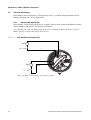
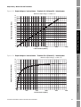
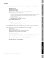
Figure 5-2
Safe area mA output load resistance values
Rmax = (Vsupply – 12)/0.023
If communicating with HART, a minimum of 250 Ω and 17.5 V is required
1000
900
700
600
500
Output Wiring – CIO Transmitters
External resistor Rload (Ohms)
800
400
300
OPERATING REGION
200
100
0
12
14
16
18
20
22
24
26
28
30
Supply voltage VDC (Volts)
Figure 5-3
Safe area HART/analog single-loop wiring
Output Wiring – FF/PA Transmitters
+
VDC
+
–
–
mA1
HARTcompatible host
or controller
Rload
(250–600 Ω
resistance)
Note: See Figure 5-2 for voltage and resistance values.
Specifications
Transmitter Installation: Model 1700 and 2700 Transmitters
35
Output Wiring – Model 1700/2700 IS Transmitters
Safe area HART multidrop wiring with SMART FAMILY™ transmitters and a configuration tool
Figure 5-4
HART-compatible
transmitters
HART-compatible
host or controller
Model 1700 or 2700
IS transmitter
SMART FAMILY
transmitter
™
24 VDC loop power
supply required for
HART 4–20 mA
passive transmitters
600 Ω maximum resistance
250 Ω minimum resistance
Note: For optimum HART communication, make sure the output loop
is single-point-grounded to an instrument-grade ground.
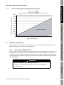
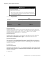
5.3.2
Safe area frequency/discrete output wiring
The following frequency/discrete output wiring diagram is an example of proper basic wiring for the
Model 1700 transmitter’s frequency output or the Model 2700 transmitter’s frequency/discrete output.
Figure 5-5
Safe area frequency/discrete output wiring
+
VDC
Counter
+
–
–
+
00042
–
Rload
Note: See Figure 5-6 for voltage and resistance values.
36
Transmitter Installation: Model 1700 and 2700 Transmitters
Output Wiring – Model 1700/2700 IS Transmitters
Output Wiring – IS Transmitters
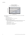
Figure 5-6
Safe area frequency/discrete output load resistance values
Rmax = (Vsupply – 4)/0.003
Rmin = (Vsupply – 25)/0.006
Absolute minimum = 100 ohms for supply voltage less than 25.6 Volts
10000
8000
7000
6000
5000
Output Wiring – CIO Transmitters
External pull-up resistor Rload range (Ohms)
9000
4000
OPERATING REGION
3000
2000
1000
0
5
5.4
7
9
11
13
15
17
19
21
Supply voltage VDC (Volts)
23
25
27
29
Hazardous area output wiring
5.4.1
Hazardous area safety parameters
The proper barrier selection will depend on what output is desired, which approval is applicable, and
many installation-specific parameters. The information that is provided about IS barrier selection is
intended as an overview. Refer to barrier manufacturers for more detailed information regarding the
use of their products. Application-specific questions should be addressed to the barrier manufacturer
or to Micro Motion.
Output Wiring – FF/PA Transmitters
The following notes and diagrams are designed to be used as a guide for wiring the Model 1700 or
Model 2700 outputs for hazardous area applications.
WARNING
Hazardous voltage can cause severe injury or death.
To reduce the risk of hazardous voltage, shut off the power before wiring the
transmitter outputs.
Specifications
Transmitter Installation: Model 1700 and 2700 Transmitters
37
Output Wiring – Model 1700/2700 IS Transmitters
WARNING
A transmitter that has been improperly wired or installed in a hazardous area
could cause an explosion.
To reduce the risk of an explosion:
•
•
Table 5-2
Make sure the transmitter is wired to meet or exceed local code requirements.
Install the transmitter in an environment that complies with the classification tag
on the transmitter. See Appendix A.
Safety parameters
Value
Parameter
4–20 mA output
Frequency/discrete output
Voltage (Ui)
30 V
30 V
Current (Ii)
300 mA
100 mA
Power (Pi)
1.0 W
0.75 W
Capacitance (Ci)
0.0005 µF
0.0005 µF
Inductance (Li)
0.0 mH
0.0 mH
Hazardous area voltage
The Model 1700 or 2700 transmitter’s safety parameters require the selected barrier’s open-circuit
voltage to be limited to less than 30 VDC (Vmax = 30 VDC). This voltage is the combination of the
maximum safety barrier voltage (typically 28 VDC) plus an additional 2 VDC for HART
communications when communicating in the hazardous area.
Hazardous area current
The Model 1700 or 2700 transmitter’s safety parameters require the selected barrier’s short-circuit
currents to sum to less than 300 mA (Imax = 300 mA) for the milliamp outputs and 100 mA
(Imax = 100 mA) for the frequency/discrete output.
Hazardous area capacitance
The capacitance (Ci) of the Model 1700 or 2700 transmitter is 0.0005 µF. This value added to the
wire capacitance (Ccable) must be lower than the maximum allowable capacitance (Ca) specified by
the IS barrier. Use the following equation to calculate the maximum length of the cable between the
transmitter and the barrier:
Ci + Ccable ≤ Ca
Hazardous area inductance
The inductance (Li) of the Model 1700 or 2700 transmitter is 0.0 mH. This value plus the field wiring
inductance (Lcable), must be lower than the maximum allowable inductance (La) specified by the IS
barrier. The following equation can then be used to calculate the maximum cable length between the
transmitter and the barrier:
Li + Lcable ≤ La
38
Transmitter Installation: Model 1700 and 2700 Transmitters
Output Wiring – Model 1700/2700 IS Transmitters
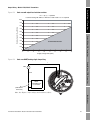
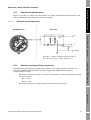
Hazardous area mA output wiring
Figure 5-7 provides an example of basic hazardous area wiring for the Model 1700 transmitter’s mA
output or the Model 2700 transmitter’s primary mA output.
Figure 5-7
Hazardous area mA output wiring
Hazardous area
Safe area
Output Wiring – IS Transmitters
5.4.2
Vin
Output Wiring – CIO Transmitters
Rbarrier
Vout
4-20 mA
Rload
Ground
Note: Rbarrier and Rload should be added together to
determine the proper Vin. Refer to Figure 5-2.
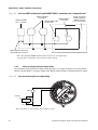
Hazardous area frequency/discrete output wiring
The following frequency/discrete output wiring diagrams are examples of proper hazardous area
wiring for the Model 1700 transmitter’s frequency output or the Model 2700 transmitter’s
frequency/discrete output:
•
•
The diagram in Figure 5-8 utilizes a galvanic isolator that has an internal 1000 Ω resistor used
for sensing current:
-
ON > 2.1 mA
-
OFF < 1.2 mA
The diagram in Figure 5-9 utilizes a barrier with external load resistance.
Output Wiring – FF/PA Transmitters
5.4.3
Specifications
Transmitter Installation: Model 1700 and 2700 Transmitters
39
Output Wiring – Model 1700/2700 IS Transmitters
Figure 5-8
Hazardous area frequency/discrete output wiring using galvanic isolator
Hazardous area
Safe area
External power supply
Vout
COUNTER
Rload
Galvanic isolator
Figure 5-9
Hazardous area frequency/discrete output wiring using barrier with external load resistance
Hazardous area
Safe area
Vin
Rbarrier
Vout
Rload
COUNTER
Ground
Note: Rbarrier and Rload should be added together to
determine the proper Vin. Refer to Figure 5-6.
40
Transmitter Installation: Model 1700 and 2700 Transmitters
Output Wiring – IS Transmitters
Chapter 6
Output Wiring – Model 2700 CIO Transmitters
6.1
Overview
Note: If you don’t know what outputs option board is in your transmitter, see Section 1.4.
Output wiring requirements depend on how you will configure the transmitter terminals. The
configuration options are shown in Table 6-1 and Figure 6-1.
If Channel B is configured as a frequency output or discrete output, it can also be configured to use
either internal or external power. Channel C can be configured to use either internal or external power,
independent of its output configuration.
•
“Internal power” means that the terminals are powered automatically by the transmitter. The
output wiring instructions do not include power setup and power wiring.
•
“External power” means that the terminals must be connected to an independent power supply.
The output wiring instructions include power setup and power wiring.
It is the user’s responsibility to verify that the specific installation meets the local and national safety
requirements and electrical codes.
6.2
Channel configuration
The six terminals are divided into three pairs, and called Channels A, B, and C. Channel A is
terminals 1 and 2; Channel B is terminals 3 and 4; and Channel C is terminals 5 and 6. Variable
assignments are governed by channel configuration. Table 6-1 and Figure 6-1 show how each channel
may be configured, and the power options for each channel.
You can use a HART Communicator or ProLink II software to configure channels. To configure
channels, see the manual entitled Series 1000 and 2000 Transmitters Configuration and Use Manual.
Output Wiring – FF/PA Transmitters
Note: The terms “active” and “passive” are sometimes used to describe internally and externally
powered outputs.
Output Wiring – CIO Transmitters
This chapter explains how to wire outputs for Model 2700 CIO transmitters (transmitters with the
configurable input/outputs board).
Note: You cannot configure the following combination: Channel B = discrete output, Channel
C = frequency output. If you need both a frequency output and a discrete output, use the following:
Channel B = frequency output, Channel C = discrete output. For more information, see the manual
entitled Series 1000 and 2000 Transmitters Configuration and Use Manual.
Specifications
Transmitter Installation: Model 1700 and 2700 Transmitters
41
Output Wiring – Model 2700 CIO Transmitters
Table 6-1
Channel
Channel configuration
Terminals
Configuration options
Power
(1)
A
1&2
mA output with HART/Bell 202
B
3&4
• mA output (default)
Internal
• Frequency output
Internal or external(2)
• Discrete output
C
5&6
Internal
Internal or external
(3)
• Frequency output (default)
Internal or external
• Discrete output
Internal or external
• Discrete input
Internal or external
(1) The Bell 202 signal is superimposed on the mA output.
(2) You must provide power to the outputs when a channel is set to external power.
(3) When configured for two frequency outputs (dual pulse), frequency output 2 is generated from the same signal that is sent
to the first frequency output. Frequency output 2 is electrically isolated but not independent.
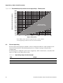
Figure 6-1
Configuration of configurable I/O terminals
+
Terminals 1 and 2 (Channel A)
mA1 output
Internal power only
HART (Bell 202) communications
–
+
Terminals 3 and 4 (Channel B)
mA2 output or FO or DO1
Power:
• mA – internal only
• FO or DO – internal or external
No communications
–
+
Terminals 5 and 6 (Channel C)
FO or DO2 or DI
Power: internal or external
No communications
–
mA = milliamp
FO = frequency output
DO = discrete output
DI = discrete input
6.3
mA output wiring
The following 4–20 mA wiring diagrams are examples of proper basic wiring for the Model 2700
primary and secondary mA outputs. The following options are shown:
•
Basic mA wiring (Figure 6-2)
•
HART/analog single-loop wiring (Figure 6-3)
•
HART multidrop wiring (Figure 6-4)
Note: If you will configure the transmitter to poll an external temperature or pressure device, you
must wire the mA output to support HART communications. You may use either HART/analog
single-loop wiring or HART multidrop wiring.
42
Transmitter Installation: Model 1700 and 2700 Transmitters
Output Wiring – Model 2700 CIO Transmitters
Output Wiring – IS Transmitters
Figure 6-2
Basic mA wiring
+
820 Ω maximum loop resistance
–
mA1
+
–
Output Wiring – CIO Transmitters
420 Ω maximum loop resistance
mA2
Figure 6-3
HART/analog single-loop wiring
Output Wiring – FF/PA Transmitters
+
HARTcompatible host
or controller
–
820 Ω maximum loop resistance
For HART communications:
• 600 Ω maximum loop resistance
• 250 Ω minimum loop resistance
Specifications
Transmitter Installation: Model 1700 and 2700 Transmitters
43
Output Wiring – Model 2700 CIO Transmitters
HART multidrop wiring with SMART FAMILY™ transmitters and a configuration tool
Figure 6-4
HART-compatible
host or controller
HART-compatible
transmitters
Model 2700 CIO
transmitter (internally
powered outputs)
600 Ω maximum resistance
250 Ω minimum resistance
6.4
SMART FAMILY™
transmitters
24 VDC loop power
supply required for
HART 4–20 mA
passive transmitters
Note: For optimum HART communication,
make sure the output loop is
single-point-grounded to an
instrument-grade ground.
Frequency output wiring
Frequency output wiring depends on whether you are wiring terminals 3 and 4 (Channel B) or
terminals 5 and 6 (Channel C), and also on whether you have configured the terminals for internal or
external power. The following diagrams are examples of proper wiring for these configurations:
•
Channel B, internal power – Figure 6-5
•
Channel B, external power – Figure 6-6
•
Channel C, internal power – Figure 6-7
•
Channel C, external power – Figure 6-8
Note: If both Channel B and Channel C are configured for frequency output, the Channel C signal is
generated from the Channel B signal, with a user-specified phase shift. The signals are electrically
isolated but not independent. This configuration is used to support dual-pulse and quadrature modes.
For more information, see the manual entitled Series 1000 and 2000 Transmitters Configuration and
Use Manual.
44
Transmitter Installation: Model 1700 and 2700 Transmitters
Output Wiring – Model 2700 CIO Transmitters
Output Wiring – IS Transmitters
Figure 6-5
Frequency output – Terminals 3 & 4 (Channel B) – Internal power
+
–
00042
Counter
Output Wiring – CIO Transmitters
Output voltage level is +15 VDC ± 3%
Note: See Figure 6-13 for output voltage versus load resistance.
Figure 6-6
Frequency output – Terminals 3 & 4 (Channel B) – External power
Output Wiring – FF/PA Transmitters
+
3–30 VDC
Counter
+
–
–
+
00042
–
Pull-up resistor
Note: See Figure 6-15 for recommended resistor versus supply voltage.
Specifications
CAUTION
Excessive current will damage the transmitter.
Do not exceed 30 VDC input. Terminal current must be less than 500 mA.
Transmitter Installation: Model 1700 and 2700 Transmitters
45
Output Wiring – Model 2700 CIO Transmitters
Figure 6-7
Frequency output – Terminals 5 & 6 (Channel C) – Internal power
+
–
00042
Counter
Output voltage level is +15 VDC ± 3%
Note: See Figure 6-14 for output voltage versus load resistance.
Figure 6-8
Frequency output – Terminals 5 & 6 (Channel C) – External power
3–30 VDC
+
+
–
+
–
00042
Counter
–
Pull-up resistor
Note: Refer to Figure 6-15 for recommended resistor versus supply voltage.
CAUTION
Excessive current will damage the transmitter.
Do not exceed 30 VDC input. Terminal current must be less than 500 mA.
46
Transmitter Installation: Model 1700 and 2700 Transmitters
Output Wiring – Model 2700 CIO Transmitters
Discrete output wiring
Discrete output (DO) wiring depends on whether you are wiring terminals 3 and 4 (Channel B) or
terminals 5 and 6 (Channel C), and also on whether you have configured the terminals for internal or
external power. The following diagrams are examples of proper wiring for these configurations:
Figure 6-9
•
Channel B, internal power – Figure 6-9
•
Channel B, external power – Figure 6-10
•
Channel C, internal power – Figure 6-11
•
Channel C, external power – Figure 6-12
Output Wiring – IS Transmitters
6.5
Discrete output 1 – Terminals 3 & 4 (Channel B) – Internal power
Output Wiring – CIO Transmitters
+
–
Total load
Note: See Figure 6-13 for output
voltage versus load information.
Output Wiring – FF/PA Transmitters
Figure 6-10 Discrete output 1 – Terminals 3 & 4 (Channel B) – External power
3–30 VDC
+
–
Pull-up resistor or DC relay
+
–
Note: See Figure 6-15 for recommended
resistor versus supply voltage.
Specifications
CAUTION
Excessive current will damage the transmitter.
Do not exceed 30 VDC input. Terminal current must be less than 500 mA.
Transmitter Installation: Model 1700 and 2700 Transmitters
47
Output Wiring – Model 2700 CIO Transmitters
Figure 6-11 Discrete output 2 – Terminals 5 & 6 (Channel C) – Internal power
+
–
Total load
Note: See Figure 6-14 for output voltage versus load.
Figure 6-12 Discrete output 2 – Terminals 5 & 6 (Channel C) – External power
3–30 VDC
+
–
Pull-up resistor or DC relay
+
–
Note: See Figure 6-15 for recommended
resistor versus supply voltage
CAUTION
Excessive current will damage the transmitter.
Do not exceed 30 VDC input. Terminal current must be less than 500 mA.
48
Transmitter Installation: Model 1700 and 2700 Transmitters
Output Wiring – Model 2700 CIO Transmitters
Output Wiring – IS Transmitters
Figure 6-13 Output voltage vs. load resistance – Terminals 3 & 4 (Channel B) – Internal power
Maximum output voltage = 15 VDC ± 3%
16
15
13
12
11
10
9
8
7
Output Wiring – CIO Transmitters
High level output voltage (Volts)
14
6
5
4
3
2
1
0
0
500
1000
1500
2000
2500
Load resistance (Ohms)
Output Wiring – FF/PA Transmitters
Figure 6-14 Output voltage vs. load resistance – Terminals 5 & 6 (Channel C) – Internal power
Maximum output voltage = 15 VDC ± 3%
16
15
High level output voltage (Volts)
14
13
12
11
10
9
8
7
6
5
4
3
Specifications
2
1
0
0
1000
2000
3000
4000
5000
Load resistance (Ohms)
Transmitter Installation: Model 1700 and 2700 Transmitters
49
Output Wiring – Model 2700 CIO Transmitters
External pull-up resistor range (Ohms)
Figure 6-15 Recommended pull-up resistor versus supply voltage – External power
4400
4200
4000
3800
3600
3400
3200
3000
2800
2600
2400
2200
2000
1800
1600
1400
1200
1000
800
600
400
Recommended
resistor value range
5
10
15
20
25
30
Supply voltage (Volts)
Note: When using a discrete output to drive a relay, choose
external pull-up to limit current to less than 500 mA.
6.6
Discrete input wiring
Discrete input wiring depends on whether you have configured terminals 5 and 6 (Channel C) for
internal or external power. The following diagrams are examples of proper wiring for these
configurations.
If external power is configured, power may be supplied by a PLC or other device, or by direct DC
input. See Table 6-2 for input voltage ranges.
Table 6-2
50
Input voltage ranges for external power
VDC
Range
3–30
High level
0–0.8
Low level
0.8–3
Undefined
Transmitter Installation: Model 1700 and 2700 Transmitters
Output Wiring – Model 2700 CIO Transmitters
Output Wiring – IS Transmitters
Figure 6-16 Discrete input – Terminals 5 & 6 (Channel C) – Internal power
+
–
Output Wiring – CIO Transmitters
Figure 6-17 Discrete input – Terminals 5 & 6 (Channel C) – External power
+
Output Wiring – FF/PA Transmitters
PLC or
other device
+
–
–
VDC
(see Table 6-2)
OR
Direct DC input
(see Table 6-2)
Specifications
Transmitter Installation: Model 1700 and 2700 Transmitters
51
52
Transmitter Installation: Model 1700 and 2700 Transmitters
Output Wiring – IS Transmitters
Chapter 7
Output Wiring – Model 2700 FF and
PA Transmitters
Overview
This chapter explains how to wire outputs for Model 2700 FF and PA transmitters (transmitters with
the FOUNDATION fieldbus and Profibus-PA output boards).
Note: If you don’t know what outputs option board is in your transmitter, see Section 1.4.
It is the user’s responsibility to verify that the specific installation meets the local and national safety
requirements and electrical codes.
7.2
FOUNDATION fieldbus wiring
Wire the transmitter to the fieldbus segment according to the diagram in Figure 7-1. Follow all local
safety regulations. The transmitter is FISCO approved — see Section A.1.1.
Figure 7-1
Output Wiring – CIO Transmitters
7.1
Connecting the fieldbus communication wires
FOUNDATION fieldbus per FOUNDATION
fieldbus wiring specification
Spur to fieldbus per
FOUNDATION fieldbus
wiring specification
Terminals 3–6
Output Wiring – FF/PA Transmitters
Fieldbus
power
supply
Terminals 1–2
{
Specifications
Note: Terminals 3 through 6 are not used.
Note: The fieldbus communication terminals (1 and 2) are polarity insensitive.
Transmitter Installation: Model 1700 and 2700 Transmitters
53
Output Wiring – Model 2700 FF and PA Transmitters
7.3
Profibus-PA wiring
Wire the transmitter to the Profibus-PA segment according to the diagram in Figure 7-2. Follow all
local safety regulations. The transmitter is FISCO approved — see Section A.1.1.
Figure 7-2
Connecting the Profibus-PA communication wires
Profibus-PA segment per Profibus-PA
User and Installation Guideline
published by PNO
Bus
power
supply
Spur to Profibus-PA segment per
Profibus-PA User and Installation
Guideline published by PNO
Terminals 3–6
Terminals 1–2
{
Note: Terminals 3 through 6 are not used.
Note: The Profibus communication terminals (1 and 2) are polarity insensitive.
Note: If you want intrinsically safe wiring, see the Profibus-PA User and
Installation Guide published by PNO.
54
Transmitter Installation: Model 1700 and 2700 Transmitters
Output Wiring – IS Transmitters
Appendix A
Specifications
A.1
Functional specifications
The Model 1700 or 2700 transmitter’s functional specifications include:
Electrical connections
•
Input/output signals
•
Digital communication
•
Power supply
•
Environmental requirements
•
Ambient temperature effect
•
EMC compliance
A.1.1
Output Wiring – CIO Transmitters
•
Electrical connections
Output connections
•
The Model 1700/2700 with analog outputs option board has one pair of wiring terminals for
digital communications (Modbus or HART protocol on RS-485)
•
On the Model 2700 with Foundation fieldbus or Profibus-PA, terminals 3–6 are not used.
Screw terminals accept one or two solid conductors, 14 to 12 AWG (2,5 to 4,0 mm2), or one or two
stranded conductors, 22 to 14 AWG (0,34 to 2,5 mm2).
Power connection
The transmitter has two pairs of wiring terminals for the power connection:
•
One pair of wiring terminals accepts AC or DC power
•
One internal ground lug for power-supply ground wiring
Output Wiring – FF/PA Transmitters
The transmitter has two (Model 1700) or three (Model 2700) pairs of wiring terminals for
transmitter outputs.
Screw terminals accept one or two solid conductors, 14 to 12 AWG (2,5 to 4,0 mm2), or one or two
stranded conductors, 22 to 14 AWG (0,34 to 2,5 mm2).
Specifications
Service port connection
The transmitter has two clips for temporary connection to the service port.
Transmitter Installation: Model 1700 and 2700 Transmitters
55
Specifications
Core processor connection
The transmitter has two pairs of wiring terminals for the 4-wire connection to the core processor:
•
One pair is used for the RS-485 connection
•
One pair is used to supply power to the core processor
Plug connectors accept stranded or solid conductors, 24 to 12 AWG (0,2 to 2,5 mm2).
FISCO approved
Model 2700 transmitters with FOUNDATION fieldbus or Profibus-PA are FISCO approved with the
following entity parameters:
•
Ui = 30 V
•
Ii = 380 mA
•
Pi = 5.32 W
•
Ci = 0.0002 µF
•
Li = 0.0 mH
A.1.2
Input/output signals
Input signal from sensor
•
4-wire remote: one intrinsically safe 4-wire mating connector
•
9-wire remote: two intrinsically safe terminal blocks with 3 sockets and one intrinsically safe
terminal block with 4 sockets (only 3 sockets are used)
•
Remote core processor with remote transmitter:
-
Core processor: two intrinsically safe terminal blocks with 3 sockets and one intrinsically
safe terminal block with 4 sockets (only 3 sockets are used)
-
Transmitter: one intrinsically safe 4-wire mating connector
Model 1700/2700 transmitters with non-intrinsically safe analog outputs option board
(output option code A)
One 4–20 mA output
56
•
Not intrinsically safe
•
Internally powered (active)
•
Isolated to ±50 VDC from all other outputs and earth ground
•
Maximum load limit: 820 Ohms
•
Model 1700 can report mass flow or volume flow; Model 2700 can report mass flow, volume
flow, density, temperature, or drive gain; transmitters with the petroleum measurement
application (API) or enhanced density application can also report standard volume flow and
density at reference temperature
•
Linear with process from 3.8 to 20.5 mA, per NAMUR NE43 (June 1994)
Transmitter Installation: Model 1700 and 2700 Transmitters
Specifications
•
Not intrinsically safe
•
Internally powered (active)
•
Maximum current: 100 mA
•
Output voltage: +24 VDC ±3%, with a 2.2 kohm internal pull-up resistor
•
Frequency/pulse output (Model 1700/2700):
Can be used to indicate either flow rate or total; Model 1700 output reports the same flow
variable as the mA output, Model 2700 output is independent from mA output
-
Scalable to 10,000 Hz
-
Linear with flow rate to 12,500 Hz
-
Configurable polarity: active high or active low
Output Wiring – CIO Transmitters
•
-
Discrete output (Model 2700 only):
-
Can report event 1, event 2, event 1 or 2, flow direction, flow switch, calibration in
progress, or fault
-
Maximum sink capability: 500 mA
-
Configurable polarity: active high or active low
Output Wiring – IS Transmitters
One frequency/pulse output (Model 1700 transmitters) or frequency/pulse/discrete output (Model
2700 transmitters):
Model 1700/2700 transmitters with intrinsically safe outputs option board (output option code D)
Model 1700 has one 4–20 mA output; Model 2700 has two 4–20 mA outputs:
Intrinsically safe
•
Externally powered (passive)
•
Isolated to ±50 VDC from all other outputs and earth ground
•
Maximum input voltage: 30 VDC, 1 watt maximum
•
Maximum current: 300 mA
•
Model 1700 can report mass flow or volume flow; Model 2700 can report mass flow, volume
flow, density, temperature, or drive gain; transmitters with the petroleum measurement
application (API) or enhanced density application can also report standard volume flow and
density at reference temperature
•
Linear with process from 3.8 to 20.5 mA, per NAMUR NE43 (June 1994)
•
Maximum load limits: see following chart
Output Wiring – FF/PA Transmitters
•
Specifications
Transmitter Installation: Model 1700 and 2700 Transmitters
57
Specifications
mA Output Load Resistance Value
Rmax = (Vsupply - 12)/0.023*
*If communicating with HART a minimum of 250 Ohms
and 17.75 V supply is needed
1000
External resistor (Ohms)
900
800
700
600
500
400
300
Operating
Region
200
100
0
12
14
16
18
20
22
24
26
28
30
Supply voltage (volts)
One frequency/pulse output (Model 1700 transmitters) or frequency/pulse/discrete output (Model
2700 transmitters):
58
•
Intrinsically safe
•
Externally powered (passive)
•
Maximum input voltage: 30 VDC, 0.75 watt maximum
•
Maximum current: 100 mA
•
Frequency/pulse output (Model 1700/2700):
-
Can be used to indicate either flow rate or total; Model 1700 output reports the same flow
variable as the mA output, Model 2700 output is independent from mA output
-
Scalable to 10,000 Hz
-
Linear with flow rate to 12,500 Hz
-
Configurable polarity: active high or active low
-
Maximum load limit: see following chart
Transmitter Installation: Model 1700 and 2700 Transmitters
Specifications
Output Wiring – IS Transmitters
Frequency Output Load Resistance Value
Rmax = (Vsupply - 4)/0.003
*Rmin = (Vsupply - 25)/0.006
*Absolute minimum = 100 Ohms for Vsupply < 25.6 volts
10000
8000
7000
6000
5000
4000
Operating
Region
3000
2000
Output Wiring – CIO Transmitters
External resistor (Ohms)
9000
1000
0
5
7
9
11
13
15
17
19
21
23
25
27
29
Supply voltage (volts)
•
Discrete output (Model 2700 only):
-
Can report event 1, event 2, event 1 or 2, flow direction, flow switch, calibration in
progress, or fault
-
Maximum sink capability: 500 mA
-
Configurable polarity: active high or active low
Output Wiring – FF/PA Transmitters
Model 2700 transmitters with non-intrinsically safe configurable input/outputs option board
(output option code B or C)
One or two 4–20 mA outputs:
•
Channel A is always an mA output; Channel B is configurable as an mA output
•
Not intrinsically safe
•
Internally powered (active)
•
Isolated to ±50 VDC from all other outputs and earth ground
•
Maximum load limit:
-
Channel A (mA1): 820 Ohms
-
Channel B (mA2): 420 Ohms
•
Can report mass flow, volume flow, density, temperature, or drive gain; transmitters with the
petroleum measurement application (API) or enhanced density application can also report
standard volume flow and density at reference temperature
•
Linear with process from 3.8 to 20.5 mA, per NAMUR NE43 (June 1994)
Specifications
Transmitter Installation: Model 1700 and 2700 Transmitters
59
Specifications
One or two frequency/pulse outputs:
•
Channels B and C are configurable as frequency/pulse outputs
•
If both are configured for frequency/pulse:
-
The channels function as a dual-pulse output which reports a single process variable.
Channels are electrically isolated but not independent
-
Output on channel C can be phase-shifted 0, 90, or 180 degrees from the output on channel
B, or the dual-pulse output can be set to quadrature mode
•
Not intrinsically safe
•
Configurable for internal or external power (active or passive):
-
If internally powered, output voltage is 15 VDC ±3%, internal 2.2 kohm pull-up
-
If externally powered, output voltage is 3–30 VDC maximum, sinking up to 500 mA at
30 VDC maximum
•
Scalable to 10,000 Hz
•
Can report mass flow rate or volume flow rate, which can be used to indicate flow rate or total
flow
•
Linear with flow rate to 12,500 Hz
•
Configurable polarity: active high or active low
One or two discrete outputs:
•
Channels B and C are configurable as discrete outputs
•
Can report event 1, event 2, event 1 & 2, flow direction, flow switch, calibration in progress, or
fault
•
Maximum sink capability: 500 mA
•
Configurable for internal or external power (active or passive):
•
-
If internally powered, output voltage is 15 VDC ±3%, internal 2.2 kohm pull-up
-
If externally powered, output voltage is 3–30 VDC maximum, sinking up to 500 mA at
30 VDC maximum
Configurable polarity: active high or active low
One discrete input:
•
Channel C is configurable as a discrete input
•
Not intrinsically safe
•
Configurable for internal or external power:
•
-
Internal power: 15 VDC, 7 mA maximum source current
-
External power: 3–30 VDC maximum
Can be used to start flowmeter zeroing procedure, reset mass total, reset volume total, reset
corrected volume total, or reset all totals
Model 2700 transmitters with FOUNDATION fieldbus outputs option board (output option code E)
One FOUNDATION fieldbus H1 output:
60
-
FOUNDATION fieldbus wiring is intrinsically safe with an intrinsically safe power supply
-
Manchester-encoded digital signal conforms to IEC 1158-2
Transmitter Installation: Model 1700 and 2700 Transmitters
Specifications
Output Wiring – IS Transmitters
Model 2700 transmitters with Profibus-PA outputs option board (output option code G)
One Profibus-PA output:
A.1.3
-
Profibus-PA wiring is intrinsically safe with an intrinsically safe Profibus-PA network
power supply
-
Manchester-encoded digital signal conforms to IEC 1158-2
Digital communication
Model 1700/2700 transmitters support the following digital communications:
Service port
One service port can be used for temporary connection only
•
Address 111
•
Uses RS-485 Modbus RTU signal, 38.4 kilobaud, one stop bit, no parity
HART/Bell202
A HART/Bell202 signal can be superimposed on the primary mA output and used for interface with a
host system:
•
Frequency: 1.2 and 2.2 kHz
•
Amplitude: 0.8 mA peak-to-peak
•
1200 baud
•
Requires 250 to 600 Ohms load resistance
Output Wiring – FF/PA Transmitters
HART/RS485 or Modbus/RS485 (transmitters with analog outputs option board only)
One pair of terminals provides RS-485 communications:
•
Can be used for direct connection to a HART or Modbus host system
•
Accepts baud rates between 1200 baud and 38.4 kilobaud
FOUNDATION fieldbus or Profibus-PA transmitters
One pair of terminals provides FOUNDATION fieldbus or Profibus-PA communications:
•
A.1.4
Output Wiring – CIO Transmitters
•
Resource, transducer, and function blocks per FOUNDATION or Profibus specification
Power supply
The Model 1700/2700 transmitter’s power supply:
Has a self-switching AC/DC input
•
Complies with low voltage directive 73/23/EEC per IEC 1010-1 with amendment 2
•
Meets Installation (Overvoltage) Category II, Pollution Degree 2 requirements
•
Has an IEC 127–1.25 slowblow fuse
Specifications
•
AC power requirements
85 to 265 VAC, 50/60 Hz, 6 watts typical, 11 watts maximum
Transmitter Installation: Model 1700 and 2700 Transmitters
61
Specifications
DC power requirements
•
18 to 100 VDC, 6 watts typical, 11 watts maximum
•
At startup, transmitter power source must provide a minimum of 1.5 amps of short-term
current at a minimum of 18 volts at the transmitter power input terminals
•
Minimum 22 VDC with 1000 feet (300 meters) of 18 AWG (0,8 mm2) power supply cable
A.1.5
Environmental requirements
Ambient temperature limits
•
Operation: –40 to +140 °F (–40 to +60 °C)
•
Storage: –40 to +140 °F (–40 to +60 °C)
Display responsiveness decreases, and display may become difficult to read, below –4 °F (–20 °C).
Above 131 °F (55 °C), some darkening of display may occur.
If possible, install the transmitter in a location that will prevent direct exposure to sunlight.
Different ambient temperature requirements may apply when installing the transmitter in a hazardous
area. Refer to the approval documentation shipped with the transmitter or available on the Micro
Motion web site.
Humidity limits
Relative humidity between 5 and 95%, non-condensing at 140 °F (60 °C)
Vibration limits
The transmitter meets IEC 68.2.6, endurance sweep, 5 to 2000 Hz, 50 sweep cycles at 1.0 g
A.1.6
Ambient temperature effect
On analog outputs ±0.005% of span per °C
A.1.7
EMC compliance
The transmitter complies with the following EMI effects standards:
A.2
•
NAMUR NE21 (May 1999) with the exception of Voltage Dip when powered by 24 VDC
•
Meets EMC directive 89/336/EEC per EN 61326 Industrial
Hazardous area classifications
The transmitter may have a tag listing hazardous area classifications, which indicate suitability for
installation in the hazardous areas described in this section.
A.2.1
UL and CSA
Ambient temperature is limited to –40 to +131 °F (–40 to +55 °C) for UL compliance.
Ambient temperature is limited to –40 to +140 °F (–40 to +60 °C) for CSA compliance.
62
Transmitter Installation: Model 1700 and 2700 Transmitters
Specifications
Class I, Division 1, Groups C and D. Class II, Division 1, Groups E, F, and G explosion proof (when
installed with approved conduit seals). Otherwise, Class I, Division 2, Groups A, B, C, and D.
Outputs
Provides nonincendive sensor outputs for use in Class I, Division 2, Groups A, B, C, and D; or
intrinsically safe sensor outputs for use in Class I, Division 1, Groups C and D or Class II, Division 1,
Groups E, F, and G.
A.2.2
Output Wiring – IS Transmitters
Transmitter
ATEX and IECEx
Ambient temperature is limited to below 131 °F (55 °C) for ATEX and IECEx compliance.
Output Wiring – CIO Transmitters
Model 1700 or 2700 transmitter with the analog or configurable input/outputs option board
All ATEX models are CE 0575
II 2G and are suitable for installation in Zone 1 (gas) hazardous
areas with the following classification codes:
Table A-1
ATEX and IECEx classification codes for Model 1700/2700 AN or CIO transmitters
ATEX
IECEx
• With display
EEx d [ib] IIB+H2 T5
Ex d [ib] IIB+H2 T5
• Without display
EEx d [ib] IIC T5
Ex d [ib] IIC T5
• With display
EEx de [ib] IIB+H2 T5
Ex de [ib] IIB+H2 T5
• Without display
EEx de [ib] IIC T5
Ex de [ib] IIC T5
Flameproof when installed with approved cable glands:
Increased safety when installed with approved cable glands:
Output Wiring – FF/PA Transmitters
Model 1700 or 2700 transmitter with the intrinsically safe, FOUNDATION fieldbus, or
Profibus-PA outputs option board
All ATEX models are CE 0575
following classification codes:
Table A-2
II 2(1)G, and are suitable for installation in areas with the
ATEX and IECEx classification codes for Model 1700/2700 IS, FF, and PA transmitters
ATEX
IECEx
• With display
EEx d [ia/ib] IIB+H2 T5
Ex d [ia/ib] IIB+H2 T5
• Without display
EEx d [ia/ib] IIC T5
Ex d [ia/ib] IIC T5
Flameproof when installed with approved cable glands:
Increased safety when installed with approved cable glands:
EEx de [ia/ib] IIB+H2 T5
Ex de [ia/ib] IIB+H2 T5
• Without display
EEx de [ia/ib] IIC T5
Ex de [ia/ib] IIC T5
A.3
Specifications
• With display
Performance specifications
For performance specifications, refer to the sensor specifications.
Transmitter Installation: Model 1700 and 2700 Transmitters
63
Specifications
A.4
Physical specifications
The physical specifications of the transmitter include:
•
Housing
•
Mounting
•
Interface/display (optional)
•
Weight
•
Dimensions
A.4.1
Housing
NEMA 4X (IP67) epoxy painted cast aluminum housing.
Terminal compartment contains output terminals, power terminals and service-port terminals. The
output terminals are physically separated from the power- and service-port terminals.
•
The electronics compartment contains all electronics and the standard display.
•
The sensor compartment contains the wiring terminals for connection to the core processor on
the sensor.
Screw-terminal on housing for chassis ground.
Cable gland entrances are either 1/2″–14 NPT or M20 × 1.5 female conduit ports.
A.4.2
Mounting
Model 1700/2700 transmitters are available integrally mounted to some Micro Motion sensors, or in
two remote-mount configurations.
•
Remote-mount transmitters include a mounting bracket, and require 4-wire or 9-wire signal
cables between the sensor and the transmitter. Maximum distance from other flowmeter
components depends on the installation type and cable type, as described in Table A-3.
•
The transmitter can be rotated on the sensor or the mounting bracket, up to 360° in
90° increments.
Table A-3
Maximum cable lengths
Cable type
Wire gauge
Maximum length
Micro Motion 9-wire
Not applicable
60 feet (20 meters)
Micro Motion 4-wire
Not applicable
1000 feet (300 meters)
User-supplied 4-wire
• Power wires (VDC)
22 AWG (0,35 mm2)
500 feet (150 meters)
2
18 AWG (0,8 mm )
1000 feet (300 meters)
22 AWG (0,35 mm2) or larger
1000 feet (300 meters)
20 AWG (0,5 mm )
• Signal wires (RS-485)
64
300 feet (90 meters)
2
Transmitter Installation: Model 1700 and 2700 Transmitters
Specifications
Interface/display
The transmitter may be ordered with or without a display. The characteristics of the display are as
follows:
•
•
-
LCD line 1 lists the process variable, line 2 lists engineering unit of measure through a
non-glare tempered glass lens
-
Display controls feature optical switches that are operated through the glass with a red
LED indicator to show that the “button” has been pressed
To facilitate various mounting orientations, the display can rotate 360° on the transmitter in
90° increments
Output Wiring – CIO Transmitters
A.4.4
Segmented 2-line display with LCD screen with optical controls and flowmeter-status LED is
suitable for hazardous area installation
Weight
For the weight of a transmitter mounted integrally with a sensor, refer to the sensor specifications.
The 4-wire remote transmitter weighs:
•
With display: 8 lb (3,6 kg)
•
Without display: 7 lb (3,2 kg)
The 9-wire remote transmitter/core processor assembly weighs:
•
With display: 14 lb (6,3 kg)
•
Without display: 13 lb (5,9 kg)
Dimensions
Output Wiring – FF/PA Transmitters
A.4.5
Output Wiring – IS Transmitters
A.4.3
Figures A-1 through A-5 show the dimensions of the Model 1700 or 2700 transmitter with and
without a display, the transmitter/core processor assembly with and without a display, and the standalone core processor. For dimensions of integrally mounted transmitters and sensors, refer to the
product data sheet for your sensor.
Specifications
Transmitter Installation: Model 1700 and 2700 Transmitters
65
Specifications
Figure A-1
Dimensions – Model 1700/2700 transmitter with display
inches
Dimensions in (mm)
6 13/16
(174)
2 7/16
(62)
3 15/16
(99)
3 × 1/2″–14 NPT
or M20 × 1.5
Ø 4 11/16
(119)
2 11/16 (69)
4 11/16
(119)
1
(25)
1 7/8 (47)
2 13/16
(71)
2 1/4
(57)
3 11/16
(93)
4 1/2
(114)
1 3/4
(45)
2 13/16
(71)
4 1/2
(114)
4 5/16
(110)
4 × Ø3/8
(10)
2 1/4
(57)
8 7/16
(214)
Wall mount
9 5/16
(237)
4 3/4
(120)
To 1/2–NPT
or M20
To centerline of
2″ pipe (pipe mount)
Note: These dimensions apply to the transmitter in 4-wire remote installations or remote core
processor with remote transmitter installations. See Figure 2-1.
66
Transmitter Installation: Model 1700 and 2700 Transmitters
Specifications
Output Wiring – IS Transmitters
Figure A-2
Dimensions – Model 1700/2700 transmitter without display
inches
Dimensions in (mm)
2 15/16
(74)
2 7/16
(62)
13/16
(21)
3 × 1/2″–14 NPT
or M20 × 1.5
Ø 4 1/16
(104)
2 11/16 (69)
1
(25)
4 7/16
(113)
1 7/8 (47)
3 11/16
2 13/16 (93)
(71)
2 1/4
(57)
Output Wiring – CIO Transmitters
5 13/16
(148)
4 1/2
(114)
1 3/4
(45)
4 5/16
(110)
7 7/16
(188)
2 1/4
(57)
4 3/4
(120)
8 5/16
(211)
To centerline of
2″ pipe (pipe mount)
Output Wiring – FF/PA Transmitters
2 13/16
(71)
4 1/2
(114)
4 × Ø3/8
(10)
Wall mount
To 1/2–NPT
or M20
Note: These dimensions apply to the transmitter in 4-wire remote installations or remote core
processor with remote transmitter installations. See Figure 2-1.
Specifications
Transmitter Installation: Model 1700 and 2700 Transmitters
67
Specifications
Figure A-3
Dimensions – Model 1700/2700 transmitter/core processor assembly with display
inches
Dimensions in (mm)
6 13/16
(174)
2 7/16
(62)
3 15/16
(99)
2 × 1/2″ –14 NPT
or M20 × 1.5
2 11/16
(69)
2 5/8
(66)
Ø4 11/16
(119)
6 5/16
(160)
3 13/16
(97)
2 13/16
(71)
5 7/16
(139)
2 13/16
(71)
2 13/16
(71)
4 1/2
(114)
4 × Ø3/8
(10)
3 1/16
(78)
13/16
(21)
3/4″–14 NPT
6 3/16
(158)
7 3/16
(182)
8 11/16
(220)
9 5/8
(244)
To centerline of 2″ pipe
(pipe mount)
3
(76)
5 11/16
(144)
Note: These dimensions apply only to the transmitter/core processor assembly in 9-wire remote
installations. See Figure 2-1.
68
Transmitter Installation: Model 1700 and 2700 Transmitters
Specifications
Output Wiring – IS Transmitters
Figure A-4
Dimensions – Model 1700/2700 transmitter/core processor assembly without display
inches
Dimensions in (mm)
2 15/16
(74)
13/16
(21)
2 × 1/2″–14 NPT
or M20 × 1.5
2 7/16
(62)
Ø4 1/16
(104)
2 11/16
(69)
2 5/8
(66)
5 7/16
(139)
2 13/16
(71)
4 1/2
(114)
4 × Ø3/8
(10)
3 13/16
(97)
2 13/16
(71)
6 3/16
(158)
3/4″–14 NPT
Output Wiring – FF/PA Transmitters
2 13/16
(71)
6 1/16
(154)
Output Wiring – CIO Transmitters
5 13/16
(148)
3 1/16
(78)
4 9/16
(116)
7 11/16
(195)
8 5/8
(219)
To centerline of 2″ pipe
(pipe mount)
3
(76)
5 11/16
(144)
Note: These dimensions apply only to the transmitter/core processor assembly in 9-wire remote
installations. See Figure 2-1.
Specifications
Transmitter Installation: Model 1700 and 2700 Transmitters
69
Specifications
Figure A-5
Dimensions – Remote core processor
inches
Dimensions in (mm)
Ø4 3/8
(111)
5 11/16
(144)
2×3
(76)
5 1/2 (140)
To centerline
of 2″ pipe
Pipe mount
4 9/16
(116)
Wall mount
2 1/4
(57)
1/2″–14 NPT
or
M20 × 1.5
2 1/2
(64)
2 3/8
(61)
1 11/16
(43)
2 5/8
(67)
3 5/16
(84)
6 3/16
(158)
4 × Ø3/8
(10)
2 13/16
(71)
3/4″–14 NPT
2 13/16
(71)
4 1/2
(114)
Note: These dimensions apply only to the core processor component in remote core processor with
remote transmitter installations. See Figure 2-1.
70
Transmitter Installation: Model 1700 and 2700 Transmitters
Index
Index
A
Accessibility 9
Ambient temperature effect 62
ATEX
installation requirements 7
specifications 62
C
Cable
maximum cable length 9
types 19
4-wire cable 20
9-wire cable 20
Channel configuration 41
Clearance 9
Core processor 2
components in remote core processor 14
mounting the remote 13
CSA
installation requirements 7
specifications 62
D
Digital communications
specifications 61
Dimensions 65
Display
components 17
rotating 16
E
Electrical connections
specifications 55
EMC compliance 62
Environmental requirements 7
specifications 62
F
FISCO 56
Flowmeter components 2
FOUNDATION fieldbus wiring 53
Four-wire remote wiring 20
G
Grounding requirements 15
Transmitter Installation: Model 1700 and 2700 Transmitters
H
Hazardous area classifications 7
specifications 62
Housing specifications 64
Humidity limits 7
I
IECEx
installation requirements 7
specifications 62
Input/output signals
specifications 56
Installation
accessibility 9
cable types 19
channel configuration 41
clearance 9
environmental requirements 7
grounding 15
hazardous areas 7
humidity limits 7
maximum cable length 9
mounting the remote core processor 13
mounting the transmitter 9
4-wire remote installations 11
9-wire remote installations 12
integral installations 10
remote core processor with remote
transmitter installations 11
power source requirements 7
power supply 16
rotating the display 16
temperature limits 7
transmitter specifications 55
type 2
vibration limits 7
wiring for 4-wire remote installations 20
wiring for 9-wire remote 21
wiring instructions for remote core processor
with remote transmitter installations 23
wiring outputs
Model 1700/2700 AN transmitters 29
Model 1700/2700 IS transmitters 33
Model 2700 CIO transmitters 41
wiring transmitter to sensor 19
Installation architecture 5
71
Index
Interface/display
specifications 65
J
Junction box 2
L
Location, determining appropriate 7
M
Mounting
maintaining accessibility 9
remote core processor 13
specifications 64
transmitter 9
4-wire remote installations 11
9-wire remote installations 12
integral installations 10
remote core processor with remote
transmitter installations 11
N
Nine-wire remote wiring 21
O
Output wiring
Model 1700/2700 AN transmitters 29
analog outputs 30
HART multidrop 32
HART/analog single-loop 31
output terminals and output types 29
Model 1700/2700 IS transmitters 33
hazardous area 37
frequency/discrete output 39
mA outputs 39
safety parameters 37
output terminals and output types 33
safe area 34
frequency/discrete output 36
HART multidrop 36
HART/analog single-loop 35
mA outputs 34
Model 2700 CIO transmitters 41
discrete input 50
discrete output 47
frequency output 44
HART multidrop 44
HART/analog single-loop 43
mA output 42
output terminals and output types 41
Model 2700 FF transmitters 53
Model 2700 PA transmitters 53
72
P
Performance specifications 63
Physical specifications 64
Power source requirements 7
Power supply
installation 16
specifications 61
Profibus-PA wiring 54
R
Remote core processor with remote transmitter
wiring instructions 23
Rotating the display 16
S
Safety messages 1
Safety parameters
hazardous area wiring for Model 1700/2700 IS
transmitters 37
Sensor 2
Specifications 55
ambient temperature effect 62
digital communications 61
dimensions 65
electrical connections 55
EMC compliance 62
environmental requirements 62
FISCO 56
functional 55
hazardous area classifications 62
housing 64
input/output signals 56
interface/display 65
mounting 64
performance 63
physical 64
power supply 61
weight 65
T
Temperature limits 7
Transmitter 2
components
4-wire remote installations 12
9-wire remote installations 13
remote core processor with remote
transmitter installations 12
installing 1, 5
mounting 9
4-wire remote installations 11
9-wire remote installations 12
integral installations 10
Transmitter Installation: Model 1700 and 2700 Transmitters
Index
Index
remote core processor with remote
transmitter installations 11
outputs option board type 2
type 2
U
UL
installation requirements 7
specifications 62
V
Vibration limits 7
W
Weight 65
Wiring
instructions
4-wire remote 20
9-wire remote 21
remote core processor with remote
transmitter installations 23
maximum cable length 9
output
See Output wiring
transmitter to sensor 19
Transmitter Installation: Model 1700 and 2700 Transmitters
73
74
Transmitter Installation: Model 1700 and 2700 Transmitters
©2005, Micro Motion, Inc. All rights reserved. P/N 20001700, Rev. B
*20001700*
For the latest Micro Motion product specifications, view the
PRODUCTS section of our web site at www.micromotion.com
Micro Motion Inc. USA
Worldwide Headquarters
7070 Winchester Circle
Boulder, Colorado 80301
T (303) 527-5200
(800) 522-6277
F (303) 530-8459
Micro Motion Europe
Micro Motion Asia
Emerson Process Management
Wiltonstraat 30
3905 KW Veenendaal
The Netherlands
T +31 (0) 318 495 670
F +31 (0) 318 495 689
Emerson Process Management
1 Pandan Crescent
Singapore 128461
Republic of Singapore
T (65) 6777-8211
F (65) 6770-8003
Micro Motion United Kingdom
Micro Motion Japan
Emerson Process Management Limited
Horsfield Way
Bredbury Industrial Estate
Stockport SK6 2SU U.K.
T 0800 966 180
F 0800 966 181
Emerson Process Management
Shinagawa NF Bldg. 5F
1-2-5, Higashi Shinagawa
Shinagawa-ku
Tokyo 140-0002 Japan
T (81) 3 5769-6803
F (81) 3 5769-6843