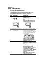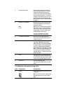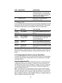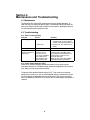
1
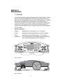
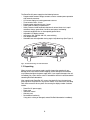
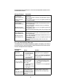
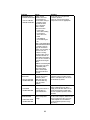
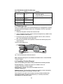
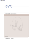
PowerPac™ HC
Power Supply
Instruction Manual
Catalog Number
164-5052
Table of Contents
Page
Safety ...........................................................................................i
Section 1 Introduction ......................................................................................1
1.1
1.2
Overview.................................................................................................1
Unpacking...............................................................................................2
Section 2
Control Features.........................................................................3
Section 3
Setup and Operation ..................................................................4
3.1
3.2
3.3
3.4
Setup and Programming a Run...............................................................4
Editing Run Parameters During a Run ....................................................5
Ending a Run ..........................................................................................6
Changing System Defaults using the Setup Menu ..................................6
Section 4
Maintenance and Troubleshooting............................................8
4.1
4.2
Maintenance ...........................................................................................8
Troubleshooting ......................................................................................8
4.2.1 Basic Troubleshooting ................................................................8
4.2.2 Power Failure Detection .............................................................8
4.2.3 User Serviceable Error Messages ..............................................9
4.2.4 Bio-Rad Serviceable Error Messages .......................................11
Replacing a Fuse..................................................................................11
Expediting Technical Support................................................................11
4.3
4.4
Appendix A Specifications ...........................................................................12
Appendix B Warranty and Ordering Information ........................................13
List of Figures
1. Front View.
2. Rear View.
3. Front View with Legs in Lowered Position.
4. Front Panel.
5. Power Leads Connected Correctly.
6. Power Leads Connected Incorrectly.
7. Rear View Showing Fuse Drawer with Notches.
© 2013 Bio-Rad Laboratories, Inc. All rights reserved.
Safety
Caution/Warning
!
!
PowerPac power supplies use high output voltages that are electrically isolated
from earth ground through a protective impedance to minimize the risk of electrical
shock to the user. The following guidelines should be observed and followed when
using a PowerPac power supply.
!
PowerPac power supplies have passed test for operation at temperatures between
0° and 40°C, with relative humidity between 0 and 95% non-condensing. Operating
the power supply outside these conditions is not recommended by Bio-Rad and
will void the warranty.
1. To ensure adequate cooling of the power supply, be sure that there is at least 6 cm
clearance around the power supply. Do not block the fan vents at the rear of the unit.
2. Always connect the power supply to a 3-prong, grounded AC outlet, using the
3-prong AC power cord provided with the power supply.
3. Bio-Rad electrophoresis cells have molded two-prong plugs that are inserted
into the power supply's high voltage output jacks. These plugs have been EN
61010* certified for safety compliance for use with PowerPac power supplies.
Use of other plugs or banana jacks is done at the user's own risk and is not
recommended by Bio-Rad. When inserting and removing the molded two-prong
plug, always grasp the plug by the molded support at the rear of the plug. Do not
grasp the individual prong ends.
4. Do not operate the power supply in extreme humidity (>95%) or where
condensation can short the internal electrical circuits of the power supply.
5. When taking the power supply into a cold room, the unit can be operated
immediately. However, when removing the power supply from the cold room,
let the unit equilibrate to room temperature for a minimum of 2 hours before
using it.
6. Never connect a high voltage output lead to earth ground. This defeats the floating
electrical isolation of the power supply and exposes the user to potentially lethal
high voltages.
Important
This instrument is intended for laboratory use only.
This product conforms to the class A standards for Electromagnetic Emissions,
intended for laboratory equipment applications. It is possible that emissions from
this product may interfere with some sensitive appliances when placed nearby or
on the same circuit as those appliances. The user should be aware of this potential
and take appropriate measures to avoid interference.
Bio-Rad's PowerPac power supplies are designed and certified to meet EN 61010*
safety standards. Certified products are safe to use when operated in accordance with
the instruction manual. This safety certification does not extend to electrophoresis
cells or accessories that are not EN 61010 certified, even when connected to this
power supply.
This instrument should not be modified or altered in any way. Alteration of this
instrument will void the manufacturer's warranty, void the EN 61010 certification,
and create a potential safety hazard for the user.
Bio-Rad is not responsible for any injury or damage caused by the use of this instrument
for purposes other than those for which it is intended, or by modifications of the instrument
not performed by Bio-Rad or an authorized agent.
*EN 61010 is an internationally accepted electrical safety standard for laboratory instruments.
Section 1
Introduction
1.1 Overview
The PowerPac HC power supply is designed to provide constant voltage, current or
power for electrophoresis applications. The power supply operates at the value
specified for the constant parameter, with limits for the other parameters. To prevent
damage to the electrophoresis cell, the PowerPac HC provides automatic
crossover to constant current, constant voltage, or constant power, depending on
which set limit is first reached. If the set limit of the non-constant parameter is
reached, the power supply will switch, making the limiting non-constant parameter
the new constant.
Output specifications:
Voltage:
Adjustable from 5 to 250 volts (V), in 1 V increments
Current :
Adjustable from 0.01 to 3.00 amperes (A), in 0.01 A increments
Power:
Adjustable from 0.05 to 300 watts (W) in 1 W increments
Output jacks:
Four sets of output jacks are provided to facilitate connection of
up to 4 identical electrophoresis cells simultaneously
1
4
ghi
6 mno
8 tuv
9wxyz
0
CE
FRONT PANEL
OUTPUT JACKS
1
5
7pqrs
setup
Fig. 2. Rear View.
3 def
jkl
EDIT
stop/home
Fig. 1. Front View.
2 abc
The PowerPac HC power supply has the following features:
•
•
•
•
•
•
•
•
•
•
•
Programmable constant voltage, constant current or constant power operation
with automatic crossover.
LCD screen displays all running parameters at once.
Timer control to 99 hr, 59 min.
Programmable methods with up to 3 steps.
Pause mode for editing run parameters.
Safety Features include automatic detection of no-load, short circuit, rapid
resistance change, ground leak, fan failure and system overheating.
Automatic completion of a run interrupted by power failure.
Adjustable LCD display contrast.
Input power 100–120/220–240 VAC, auto-switching
Four output terminals.
Stackable case with adjustable viewing angle via flip down legs (See Figure 3)
Fig. 3. Front View with Legs in Lowered Position.
1.2 Unpacking
When you receive your power supply, carefully inspect the container for any
damage which may have occurred in shipping. Severe damage to the container
may indicate damage to the power supply itself. If you suspect damage to the unit,
immediately file a claim with the carrier in accordance with their instructions before
contacting Bio-Rad Laboratories.
After unpacking the PowerPac HC, remove the plastic film from the translucent
green top case. The plastic film may leave a residue. If so, clean with a soft, damp
cloth. Also remove the die-cut plastic film covering the display window. Contents
include:
•
•
•
•
•
PowerPac HC power supply
Power cord
Instruction manual
Warranty card
Declaration of conformity
If any part is missing or damaged, contact Bio-Rad Laboratories immediately.
2
Section 2
Control Features
RUN/PAUSE KEY
ALPHANUMERIC
KEYPAD
STOP/HOME KEY
CLEAR ENTRY KEY
SETUP KEY
IR PORT
SOFT KEYS
EDIT KEY
ARROW KEYS
Fig. 4. Front Panel.
Key
Description
Run/Pause Key
• Starts or pauses a run. Pausing allows editing of the run parameter
values.
•
The corresponding LED indicates the status of the power supply.
Stop Key
• Stops the run. The display will show final run values alternating with
the "Run Stopped" screen.
•
A second stroke to the stop key clears the final run values of the
previous run and prepares the screen to repeat the run.
Reset Key
• The reset key can be used at any time during programming to clear
previous run parameters and reset to the default startup screen.
•
In the setup menu, the reset key returns settings to default values.
Setup Key
• Setup key accesses the set up menu. The setup menu allows
changes to defaults such as power failure detection, rapid
resistance change detection, alarm, and display contrast. See
pages 6–7 for details.
Constant Key
• Selects constant voltage, constant current or constant power.
•
The lighted LED below the parameters on the screen indicates the
constant parameter selected.
Cursor Keys
• Navigates among the different entry fields on the screen.
•
Values Keys
Changes the value of the selected parameter (indicated by the cursor).
If the values key is pressed continuously for more than
10 counts in either direction, +/-, the value will increase/decrease in
increments of 10 to reach the desired value faster.
3
Section 3
Setup and Operation
3.1 Setup and Programming a Run
This section guides the user through setting up the power supply for a run,
connecting the electrophoresis cell(s), programming, and running.
STEP
PROCEDURE
DESCRIPTION
1.
Connect cell(s)
The power leads are color coordinated to
the output terminals.
indicates high voltages.
Note: Power leads must be inserted
perpendicular to the curve of the case.
Fig. 5. Power Leads Connected Correctly.
Fig. 6. Power Leads Connected Incorrectly.
2.
Press the power switch located on the
right side of the unit to the ON ( I ) position.
Turn power on.
The default settings are indicated in the
home screen below:
0
00
0 00
00
Note: The firmware version number
appears on the screen momentarily
when the unit is turned ON.
3.
Select constant parameter
Press the constant key which toggles
between volts (V), amperes (A), or watts
(W).
An LED indicates the constant parameter:
V, A, and W. The cursor also indicates
the selected constant parameter,
activating the field to enter a value. The
non-constant parameters display
maximum values as a default and will act
as output limits (see step 6 to change
output limits).
Note: Constant voltage is the default
setting in the startup screen.
4
4.
Enter constant value
Press the Values keys to increase or
decrease the selected value. The keys
change the value in increments of 1,
however after a few seconds of holding
the key in either direction, +/-, the value
changes in increments of 10. If the run is
going to be untimed or continuous, and
the limits are the maximum output, proceed
to step # 9.
5.
Program time (optional)
Move the cursor to the time field using
the left/right arrow keys and enter the
values as in step 4.
0:00
hr:min
Note: Time is comprised of two fields for
hours and minutes. If values increase
past 59 min in the minutes field, an hour
will be added in the hours field and the
minutes field will restart at 00.
If no time is entered the run will be
considered untimed or continuous.
6.
Change limits (optional)
Move the cursor to the fields of the
non-constant parameters and enter the
values as in step 4.
7.
Add a step or steps (optional)
After time has been entered in the first
step, up to 2 additional steps may be
added. Move the cursor to the step field in
the upper left of the screen and press the +
Value key to add a step, then proceed to
enter run parameters as in steps 3–6 above.
Note: To review a multistep program, use
the cursor keys to move the cursor to the
step field and use +/- Values keys to scroll
through the steps.
8.
Reset
The Reset key may be pressed at any
time during the programming process to
clear all entries and return to the startup
screen (single step with default values).
9.
Start the run
Press the start/pause key.
The run may be started at any time after
step 4.
3.2 Editing Run Parameters During a Run
STEP
PROCEDURE
DESCRIPTION
1.
Pause
Press the start/pause key while a run is
in progress.
Note: The LED next to the standing man
lights up and the timer on the screen
stops.
5
STEP
PROCEDURE
DESCRIPTION
2.
Editing
Use the cursor keys and values keys to
change parameters. For multiple-step
runs, future steps may be accessed and
changed, yet the original number of
steps cannot be changed.
3.
Resume the run
Resume the run by pressing the
start/pause key again.
3.3 Ending a Run
A run may be terminated in several ways: by user intervention, automatically if time was
programmed, or due to a power failure (if power failure detection (PFd) is not enabled).
The display will indicate how the run was ended as well as its final parameters.
Run
MESSAGE
EXPLANATION
Timed or
continuous
Run Stopped
Run manually stopped by pressing the
stop key
Timed
Run Completed
Timed run ends automatically
Timed
PFd ON
Run Completed
after power fail
Run ends automatically, a power failure
occurred during the run which was
resumed automatically.
Timed or
continuous
PFd ON
Stopped after
power fail
Run manually stopped by pressing the
stop key, a power failure occurred during
the run which was resumed automatically.
PFd OFF
Aborted after
power fail
A power failure occurred and the run was
terminated.
When the stop key (or any key) is pressed again, the original settings will appear
and the PowerPac is ready to start the run again (except after a power failure with
PFd off. See Troubleshooting for details). Changes made during Pause mode will
be lost.
3.4 Changing System Defaults using the Setup Menu
The setup menu allows the user to activate the automatic power recovery function,
turn off the rapid resistance change safety function, turn off the alarm, and adjust
the display contrast.
Power Failure Detection (PFd)
The default setting for Power Failure Detection (PFd) is OFF. If a power failure (or
multiple power failures) occurs during a run when PFd is ON, the PowerPac HC
will automatically resume the run when power is restored. This occurs whether the
run is timed or continuous. After the run has been completed or stopped, PFd is
reset to its default setting, OFF.
Note: The PowerPac HC cannot distinguish between a power failure and being
turned off at the power switch. If PFd is ON, and the PowerPac HC is turned off at
the power switch during a run, the power supply will resume the run when turned
back on, possibly creating an unsafe condition. Therefore, it is important always to
stop a run before turning off the power supply.
6
Rapid Resistance Change Detection (RRCd)
The Rapid Resistance Change Detection safety feature alerts the user when the
resistance load detected by the PowerPac HC has changed by more than 25% over
a brief time-period, possibly indicating an unsafe condition. Certain applications,
such as use with the DCode or DGene systems, might exhibit resistance changes
³ 25% and trigger a shutdown erroneously before completion of the run if RRCd is
not turned off. For these applications, RDCd should be turned off. After a run has
been completed or stopped with RRCd turned OFF, RRCd is reset to its default
setting, ON.
Alarm and Contrast Settings
The PowerPac HC has an alarm that signals when a timed run is started, completed, or
when an error message occurrs. The alarm can be turned off in the setup menu, if
desired. If the alarm is turned off, it will not signal error messages.The display contrast
can also be adjusted through the PowerPac HC’s setup menu. Both of these user
adjustments are preserved in memory, regardless of completion of the run or power
shutdown. The Reset key may be used to return these settings to their defaults in the
setup menu.
STEP
PROCEDURE
DESCRIPTION
1.
Access the setup menu
Press the Setup key. This key is not
active during run and pause modes.
Default settings are as follows:
PFd: OFF RRCd: YES
ON
5
Note: The setup menu cannot be
accessed during a run.
2.
Select feature
Use the cursor keys to select a feature
to modify. Four can be adjusted.
1.
2.
PFd: Power failure detection.
RRCd: Rapid Resistance Change Detection
3.
: Alarm
4.
: Contrast
3.
Change values
The Values keys toggle between
ON/OFF for Pfd, RRCd, and alarm setting,
and adjust screen contrast from 1 through 9.
4.
Reset, if needed.
Press the reset button to return to default
values:
PFd: OFF RRCd: YES
ON
5
5.
Exit the Setup menu
Press the Setup key again.
7
Section 4
Maintenance and Troubleshooting
4.1 Maintenance
The PowerPac HC requires little maintenance to assure reliable operation. To
clean the case, first unplug the power supply. Use a damp cloth to wipe down the
outer case. Ethanol may be used to wipe the case, however, prolonged contact or
use may cloud the green translucent case.
4.2 Troubleshooting
4.2.1 Basic Troubleshooting
Problem
Cause
Solution
No display/lights/fan
1. No AC power.
1. Check if PowerPac HC is unplugged,
or problem with AC power source,
or power switch is in off position "O".
2. Blown fuse.
2. Replace fuse. See Section 4.3 for
details.
Repeated blown fuses Hardware failure
Contact Bio-Rad Technical Resources.
Leads from cell are
not long enough to fit
output jacks
Use the PowerPac Adaptor,
(Catalog number 165-5061) which
accommodates most standard 4 mm
banana plugs, to make a secure
electrical connection.
Note: Use of the PowerPac Adaptor
voids EN61010 safety provisions.
Output terminals for the
PowerPac HC are
recessed 16 mm to
meet safety regulations.
Some leads are not
long enough to make
electrical connection.
4.2.2 Power Failure Detection (PFd)
Power failure related messages provide information in the event of a power
interruption during a run. The power supply and the electrophoresis cell are not at
fault, and there is no actual corrective action.
The power failure detection default setting is OFF. That means that if a power
outage occurs during a run, the run will be aborted and the run parameters will be
lost. According to the application and user preferences, PFd may be turned ON,
which will enable the PowerPac HC to resume the run automatically when power is
restored.
8
If a power failure occurs during a run, there are several possible scenarios which
are described as follows:
Message Displayed
Explanation
RUN ABORTED
AFTER POWER FAIL
PFd was OFF.
The run, either timed or continuous, was aborted after a power
failure occurred.
After pressing the stop key to reset, the original run parameters
are no longer available.
*PRESS STOP KEY
TO RESET
RUN STOPPED
AFTER POWER FAIL
PFd was ON when a power failure occurred and the run was
resumed automatically.
The run, either timed or continuous, has been terminated by
pressing the stop key.
(Message alternates
After pressing the stop key to reset, the original run parameters
with final run parameters) are available for re-run.
Note: PFd defaults automatically to OFF after pressing the stop
key.
RUN COMPLETED
AFTER POWER FAIL
(Message alternates
final run parameters)
PFd was ON when a power failure occurred and the run was
resumed automatically.
The run was timed and automatically terminated when the set
run time was completed.
After pressing the stop key to reset, the original run parameters
are available for re-run.
Note: PFd defaults automatically to OFF when the run is
completed.
4.2.3 User Serviceable Error Messages
The following user serviceable messages may appear, interrupting a run. Refer to
this section for their cause and solution. Follow instructions on the screen to clear
the error message and resume operation.
Problem/error
message
E01 NO LOAD
DETECTED
CELL & CABLES
* PRESS STOP KEY
Cause
Solution
No load detected.
• Electrophoresis cell
not connected to the
power supply.
Verify all electrical connections.
Verify buffer levels are appropriate.
• The current load is
less than 0.01 A.
E02 SHORT CIRCUIT Short circuit detected
(over current, load
CELL & CABLES
current is greater
* POWER OFF/ON
than 3.0 A).
• Accidental shorting of
output leads.
• Shorting due to wrong
connections.
E04 REGULATING
Regulation Error.
BELOW 5V
Current drawn by the
electrophoresis system
METHOD VALUES exceeds the set current
* PRESS STOP KEY limit of the unit, at less
than 5 V.
9
Verify the electrophoresis application's
power requirements match PowerPac
HC output range.
•
•
Insure all electrical connections
are making good contact and the
cables and wire electrodes are in
good shape.
Verify buffer levels are appropriate.
Ensure the electrophoresis application
settings and power requirements
match PowerPac HC output range
Problem
Cause
Solution
E09 RESISTANCE
Change in load
CHANGE DETECTED resistance detected.
The PowerPac HC
CELL & CABLES
detects drastic changes
* PRESS STOP KEY in resistance which
may indicate failure
of the cell's power
leads or a loose
output connection.
• Loose ouput
connections leading
to intermittent
connection to the
loads.
• Cells added or
removed during the
run.
Note: Certain applications
exhibit intrinsic fluctuations
in resistance that can
trigger the Resistance
Change error message. If
this is the case, the
Resistance Change
detection feature can be
deactivated to allow an
uninterrupted completion
of the run. See Section 3.4
for details on turning off
RRCd.
Caution: Deactivating this
safety feature increases
the possibility that a
failure of the power
leads or loose output
connections will not be
detected.
E11 GROUND LEAK Insulation failure in the
DETECTED
electrical connections
outside the power
CELL & CHILLER
supply has caused a
* POWER OFF/ON
current flow that may
create an unsafe
condition.
E16 FAN FAILURE
The fan is not
FAN GRID
* POWER OFF/ON
working, either due to a
electrical failure or
physical obstruction.
E17 SYSTEM
OVERHEATING
Fan vents blocked and or
ambient temperature
too high.
FAN & RM. TEMP
* POWER OFF/ON
10
Check and correct any potential
resistance problem.
Verify all electrical connections.
Verify buffer levels are appropriate.
Check electrical connections and check
cell/chiller system for leaks. Ensure
that the electrophoresis cell rests on
an insulated, dry surface.
Inspect the fan grid to check if the fan
blade is rotating when the power
supply is turned "ON". Make sure no
foreign material has penetrated the
fan vent. If problem persists, contact
Bio-Rad.
Clear a space of at least 6 cm around
the fan vents to improve airflow. Press
any key to go to the home screen to
restart. Operate the unit within the
recommended temperature range
(0 to 40°C)
4.2.4 Bio-Rad Serviceable Error Messages
Error code
Cause
Solution
ERROR 03
* POWER OFF/ON
Output regulation
problem
ERROR 08
* POWER OFF/ON
ERROR 99
* POWER OFF/ON
ERROR 98
* POWER OFF/ON
Output regulation
problem
Hardware failure
Restart the unit by turning the power
switch OFF and ON.
Contact Bio-Rad Technical Resources
if problem persists.
Hardware failure
4.3 Replacing a fuse
If there is no display, lights, or fan, and the PowerPac HC is plugged into a working
AC power outlet with the power switch in the "ON" position, the fuse may need to
be replaced.
1. Disconnect the power cord from the electrical outlet.
2. Insert a flat blade screwdriver into the notches of the power entry module's fuse
drawer to release it. See Figure 7.
3. Remove the fuse from the fuse drawer. Replace it with 8A, 250 V, 5x20 mm,
type T fuse (Bio-Rad part number 900-8933).
4. Re-insert the fuse drawer into its position. Press the fuse drawer gently until it
snaps into place.
The unit is now ready for use.
FUSE
DRAWER
NOTCHES
Fig. 7. Rear View Showing Fuse Drawer with Notches.
Note: Repeated blowing of the fuse indicates a hardware failure. Contact Bio-Rad
Technical Support.
4.4 Expediting Technical Support
Make sure the following information is readily available before contacting Bio-Rad.
Product model no: Located in the sticker on the bottom of the unit
(example: PowerPac HC Power Supply).
Serial number: Located in the sticker on the bottom of the unit
(example: xxxBRxxxxx).
Software version: The PowerPac HC displays the software version momentarily
after switching the power ON (example: Firmware 1.00).
State clearly the error code, error message or anomaly, and the conditions that
originated the problem, including run parameters (V, A, and W) as well as the
electrophoresis cell and buffer system.
11
Appendix A
Specifications
Output specifications
Output range (programmable)
250 V, 3.0 A, 300 W
5–250 V, fully adjustable in 1 V increments
0.01–3.0 A, fully adjustable in 0.01 A
increments
Type of output
Output terminals
Timer
Pause/resume function
Display
Operating conditions
Safety compliance
EMI
Safety features
Input protection
Input power (nominal)
Dimensions (D x W x H)
Weight
1–300 W, fully adjustable in 1 W increments
Constant voltage, current, or power with
automatic crossover
4 pair recessed banana jacks in parallel
up to 99 hr, 59 min
yes
2 line, 16 character backlit LCD
0–40°C; 0–95% humidity in the absence of
condensation
EN61010
Conforms to CE standards for emissions and
immunity class A, tested only at 230 V. TÛV
EMC certification
No load detection; sudden load change
detection; ground leak detection;
overload/short circuit detection; overvoltage
protection; overheating protection
Fuse on hot and neutral
100–120/220–240 VAC, autoswitching
28.5 X 25 X 8 cm
2.0 kg
12
Appendix B
Warranty and Ordering Information
Warranty
The PowerPac HC power supply is covered by a standard Bio-Rad Laboratories
warranty. Contact your local Bio-Rad representative for details of the warranty. If
any defects should occur during this warranty period, Bio-Rad Laboratories will
replace the defective parts without charge. However, the following defects are
specifically excluded:
1. Defects caused by improper operation.
2. Repair or modification done by anyone other than Bio-Rad Laboratories or their
authorized agent.
3. Use with cables or connectors not specified by Bio-Rad Laboratories for this
power supply.
4. Deliberate or accidental misuse.
5. Damage caused by disaster.
For inquiry or request for repair service, contact your local Bio-Rad office.
Warranty Information
Model:
Serial Number:
Date of Delivery:
Warranty Period:
Ordering Information
Catalog
Number
Description
164-5052
PowerPac HC power supply, 100–120/220–240V
165-5061
PowerPac Adaptor, qty 1
165-5066
PowerPac Adaptor, qty 2
900-8933
Replacement Fuse, 8 A, 250 V, 5 x 20 mm, Type T, 1
13
Bio-Rad
Laboratories, Inc.
Web site www.bio-rad.com USA 800 424 6723 Australia 61 2 9914 2800 Austria 01 877 89 01 Belgium 09 385 55 11 Brazil 55 11 5044 5699
Canada 905 364 3435 China 86 21 6169 8500 Czech Republic 420 241 430 532 Denmark 44 52 10 00 Finland 09 804 22 00
France 01 47 95 69 65 Germany 089 31 884 0 Greece 30 210 9532 220 Hong Kong 852 2789 3300 Hungary 36 1 459 6100 India 91 124 4029300
Israel 03 963 6050 Italy 39 02 216091 Japan 03 6361 7000 Korea 82 2 3473 4460 Mexico 52 555 488 7670 The Netherlands 0318 540666
New Zealand 64 9 415 2280 Norway 23 38 41 30 Poland 48 22 331 99 99 Portugal 351 21 472 7700 Russia 7 495 721 14 04
Singapore 65 6415 3188 South Africa 27 861 246 723 Spain 34 91 590 5200 Sweden 08 555 12700 Switzerland 026 674 55 05
Taiwan 886 2 2578 7189 Thailand 800 88 22 88 United Kingdom 020 8328 2000
Life Science
Group
4006222 Rev D
US/EG
Sig 1212