1
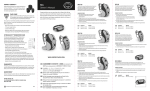
Art. Nr:
TA iQ MWD: 97050
TA iQ RWD: 97060
TA iQ FWD: 97070
TA. Service A/S · Orupgade 32 B · Orup · 4640 Faxe
Telefon +45 56 72 57 77 · Telefax +45 56 72 57 76 · www.ta-service.dk
Ver. 1.31 Eng. - 2013
Serial number:______________________
1
WARNINGS.
Please read the instructions carefully. They contain important warnings and instructions.
TA iQ power chair is not intended for users with a weight exceeding 140 kg.
TA iQ power chair should always be turned off when getting on or off of the chair and when assisted by a helper, so that
the power chair does not accidentally move if the joystick is activated.
Do not reach into or under the power chair when the seat lift or seat tilt is activated, because there is a risk of entrapment
of hand and fingers between the mechanical parts.
Check that others, especially children, aren’t too close to the power chair when the seat lift or seat tilt is activated.
The power chair is EMC tested. However, it is possible that the power chair can be affected by electromagnetic fields
from electronic devices, such as mobile phones. Similarly, it cannot be excluded that the chair can emit electromagnetic
fields that can affect the surroundings, such as alarm systems in stores.
Pay particular attention to late run when driving on ramps.
When the power chair's brakes are disengaged, the power chair may roll if it is on a sloping surface.
Slowing down by pressing the On /Off button creates the risk that the user's torso could fall over.
This could lead to, the user falling out of the power chair.
Slowing down in this manner should be avoided on sloping surfaces and ramps.
When forcing level differences, it is important that the power chair runs perpendicular to the obstacle in order to minimize
the risk that the power chair should tilt.
By forcing level differences with the seat tilted or hoisted there is a risk that the power chair can tip over. By forcing level
differences, it is therefore important that the seat is elevated as little as possible and is as close to an upright position as
possible to minimize this risk.
Driving on steeper slopes should be avoided where possible. This will affect the chairs natural stability and increase the
risk of the chair tipping over.
When driving on slopes ensure the following factors are considered
• The seat height should be as low as possible.
• The tilt and/or backrest recline will also affect stability.
• The rear most point of the back cushion on a TA iQ RWD should not be positioned behind the centre of the rear
axle/wheels. If in doubt contact TA Service A/S or your distrubutor.
• The speed is suitable and safe for the environment, excessive speed will make the chair more likely to tip.
When the power chair is used as a seat in a car, bus or similar, the power chair must always be secured with an approved
car attachment. Using 4 point car attachment the hooks must only be attached in the 4 attachment loops on the power
chairs. Fastening the hooks elsewhere will cause a high risk of danger to the user and damage to the power chair. When
using a Dahl docking system the instructions from Dahl Engineering must be followed closely. Failure to follow
instructions carefully, will cause a high risk of danger to the user and damage to the power chair.
Avoid touching leaking batteries, as the contents can be harmful.
The temperature of some surfaces can increase and get very hot when in direct sunlight. Especially the armrest, joystick
controller, back/seat and footplate surface, care should be taken to avoid touching with bare skin.
Repairs and programming of the power chair must be performed by TA Service A/S or a repairer who is authorized by
TA Service A/S.
Unauthorized programming can cause the power chair to handle in a way that could cause danger to the user or the
surroundings.
Only original parts or parts that are approved by TA Service A/S can be used.
2
PREFACE.
TA Services A/S hopes you are satisfied with your new TA iQ power chair.
TA iQ is designed to facilitate your daily movement outdoors and indoors. It has been very important to design the power
chair as small and compact as possible, without reducing the power chair's stability and handling.
WARNING!
Read the instructions carefully. They contain important warnings and instructions.
The operation of the power chair has been designed to be as simple as possible, however it is important that you read
through this manual, so you're sure to get the most out of your TA iQ.
Keep this manual so you can use it for reference.
In this manual you will find the information you need to operate the power chair. If you have questions, comments, or
suggestions, please feel free to contact us:
TA. Service A/S
Ømarksgården
Orupgade 32 B
DK - 4640 Faxe
Tel. + 45 56 72 57 77
Fax + 45 56 72 57 76
[email protected]
TA Service A/S makes continuous product development and we reserve the right to make changes.
TA iQ is tested by TÜV, and complies with standard EN 12184:2009.
TA iQ is EMC tested by the accredited test lab Delta following standards EN 12184:2009 section 9.1, PrEN 12184:2011
section 12.1 and ISO 7176-21:2003 section 5.2.
TA iQ is Climate tested by Delta in accordance to EN 12184:2009 section 8.11, PrEN 12184:2011 section 8.4 and ISO
7176-09:2009.
TA iQ is Crash tested by Dahl Engineering in accordance to ISO 10542-5 &7176-19 – 2008.
This handbook has been prepared in accordance with applicable requirements.
3
PRE-SALE INFORMATION
A) By request the user manual can be made with large font
B) The TA iQ`s designed for users with normal visual and cognizance ability. MAX. User weight 140 kg.
C) The TA iQ`s designed for use both indoors and outdoors. When you drive indoors, you must be careful in, for example,
narrow passages, when going through doors and entrances and when using lifts, ramps, etc.
D) The TA iQ is a Class B wheelchair
E) Dimensions:
TA iQ FWD: 630 mm width, 400 mm height without seat, 820 mm length.
TA iQ RWD: 630 mm width, 400 mm height without seat, 820 mm length.
TA iQ MWD: 630 mm width, 400 mm height without seat, 900mm length.
F) Reversing width all three models: 630 mm
G) Max. safe slope:
TA iQ FWD: 10°
TA iQ RWD 10°
TA iQ MWD: 10°
H) MAX Height of kerbs:
TA iQ FWD: 100 mm
TA iQ RWD 80 mm
TA iQ MWD: 80 mm
I) No removable parts will have an adverse beneficial effect on the wheelchair.
J) Standard options of all three models: electrical lift, electrical tilt and electrical backrest.
K) All three models can be used with air tyres or tires with infill
L) No programmable device is fitted to the chairs. Only authorized technical personal should program the chairs.
N) Theoretical continuous driving distance: 40 km. The distance will be reduced if the wheelchair is used frequently on
slopes, rough ground or to climb kerbs etc.
O) The backrest can be folded over the seat plate with tools, if the chairs need to be smaller for transport or storage.
P) The wheelchairs aren’t meant to be dismantled.
Q) All three models can be fitted with a “Fly kit” so the batteries don’t need to be removed from the chair during air
transport e.g.
R) The wheelchair is not intended to be used as a seat in a motor vehicle.
S) If the chairs are being used as a seat in a motor vehicle the chairs need to be fixed using the 4 point attachments with
tie-downs on the chairs or in a “Dahl docking station”.
4
CONTENTS
Warnings. ............................................................................................................................................................2 Preface.................................................................................................................................................................3 Pre-sale information............................................................................................................................................4 Contents ..............................................................................................................................................................5 Technical Data ....................................................................................................................................................6 Serial number..................................................................................................................................................7 Operating Instructions.........................................................................................................................................8 Before driving: ....................................................................................................................................................8 Performance check .........................................................................................................................................9 Getting in and out of the wheelchair ............................................................................................................10 While driving: ...................................................................................................................................................11 Braking. ........................................................................................................................................................11 Mechanical disengaging the brakes..............................................................................................................11 Emergency brake. .........................................................................................................................................12 Force of obstacles. ........................................................................................................................................12 Driving on slopes..........................................................................................................................................12 Surfaces ........................................................................................................................................................12 Driving in darkness.......................................................................................................................................13 After driving......................................................................................................................................................13 Control box ...................................................................................................................................................13 Locking Joystick...........................................................................................................................................15 Setting Menu.....................................................................................................................................................16 Setting the power functions ..............................................................................................................................17 Alternative controls/functions...........................................................................................................................18 Control box without display .........................................................................................................................18 Adjustmets ........................................................................................................................................................20 Setting the armrests. .....................................................................................................................................20 Swing- away bracket ....................................................................................................................................20 Setting up the leg rest. ..................................................................................................................................21 Mounting of hipbelt. .....................................................................................................................................21 Suspension. ...................................................................................................................................................21 Transportation by car. .......................................................................................................................................22 4 point car attachment...................................................................................................................................22 Dahl docking system ....................................................................................................................................22 Charging............................................................................................................................................................23 Disposal.............................................................................................................................................................24 resistance to ignition .........................................................................................................................................24 Warranty. ..........................................................................................................................................................24 packing and shipping ........................................................................................................................................24 Troubleshooting. ...............................................................................................................................................25 Troubleshooting – control box without display ................................................................................................26 Service and maintenance...................................................................................................................................27 Maintenance..................................................................................................................................................27 Cleaning........................................................................................................................................................27 Fuse...............................................................................................................................................................27 Batteries:.......................................................................................................................................................28 Tyre punctures: .............................................................................................................................................29 accessories and spareparts.................................................................................................................................31 Declaration of Conformity................................................................................................................................32 5
TECHNICAL DATA
Power chair Type:
Class B:
Dimensions:
Width excl. seat: 63 cm
Floor clearance: app. 7 cm. (depending on the adjustment of the springs)
Length excl. footplate / foot supports (shortest)
TA iQ FWD: 82 cm
TA iQ MWD: 90 cm
TA iQ RWD: 82 cm
Seat Mounting Height:
38,5 cm (for top plate)
40 cm (for seat plate)
41 cm (for strop plate)
Turning radius:
TA iQ FWD: 65 cm
TA iQ MWD: 45 cm
TA iQ RWD: 65 cm
Seat lift: 30 cm.
Seat tilt: 40 °
The chair's weight with seat: approx. 102 kg depending on configuration
User Weight:
Maximum user weight: 140 kg
Tires:
Tire sizes, steering wheels: 200-50 Recommended pressure: 2.0 bar / 29 psi
Tire sizes, driving wheels: 300 -8 – Recommended pressure: 2,5 bar /36 psi
In the event of puncture, the tube can be repaired the same way as a bicycle tire
tube.
Temperature:
Storage Temperature: -20° C to 50° C
Operation Temperature: -20° C to 50° C
Batteries:
2 pcs. 12V/63Ah
Type: gas-tight lead acid (Recombination battery).
Capacity: 63 Ah
Maximum charge current: 8 Ah
Battery Connection Type: Bolt F-M6
Size:
• Width: 171 mm
• Length: 261 mm
• Height incl. poles: 210 mm
Maintenance free
Engines:
2 pcs. 24V/350 Watt
Driving Data:
Maximum driving distance (theoretical): 40 km
Maximum speed, forward driving: 12,5 km / h
Maximum speed, reverse driving: 5 km / h
Max. safe slope:
TA iQ FWD: 10°
TA iQ RWD 10°
TA iQ MWD: 10°
Max height of kerbs:
TA iQ FWD: 100 mm
TA iQ RWD 80 mm
TA iQ MWD: 80 mm
Charger Specifications:
See user's guide included charger - Aura 24V / 8 A.
6
Electronics:
Penny and Giles R-Net Drive Control
Brakes:
Motor Brake and Electric Brake.
Motor brake acts as brake-lock brakes, and is activated when the control stick
is released.
From when you release the control stick and until the chair stands still there is
a small “late run” on the chair. This “late run” can be adjusted depending on
whether you want a soft or a sharp slowdown.
It is possible to set how fast the chair's slowdown will be. If this change is
wanted please contact TA Service A/S.
Electromagnetic brake is activated when the chair is stationary and serves as a
"parking" brake.
Working conditions
electrical functions
Lift actuator: 10 % (1 min. work 9 min rest)
Tilt actuator: 10 % (2 min work 18 min rest)
Back rest: 10 % (6 min/hour)
Leg rests: 10 % (6 min/hour)
Serial number
The wheelchair has a unique serial number.
The serial number is located on a label on the right
side of the wheelchair.
The label also contains other information about the
wheelchair e.g. max user weight and production time
Figure 1.
Figure 1
7
OPERATING INSTRUCTIONS.
BEFORE DRIVING:
WARNING!!
TA iQ is not intended for users with a weight exceeding 140 kg
WARNING!!
TA iQ should be turned off when entering and exiting the power chair and when assisted by a helper, so that the
power chair does not accidentally move if the joystick is activated.
CAUTION!
Smoking or use of open fire, while seated in the power chair, creates a risk of burns to the user or upholstery.
Footplate / foot rests can be locked to facilitate entry and exit.
Before you use TA iQ, check the following:
- The power chair's speed is sufficiently low.
- Any footrests are properly mounted and locked so they do not swing out while driving.
- The seat lift is set at the lowest possible level and the seat tilt is as close to horizontal (neutral) position as possible.
NB!
When the seat is raised above 6.5 cm, the power chair seat can only tilt 16 °. If the seat is not lifted higher than 6.5
cm, the seat can be tilted fully (40°).
When the seat is tilted more than 15° the seat can only be raised 6.5 cm. If the seat is not tilted more than 15°, the
seat can be lifted fully (30 cm)
When the seat is raised more than 6.5 cm or by tilted over 15° the chair speed automatic reduces by 15%.
WARNING!!
Do not reach into or under the power chair when the seat lift and seat tilt is activated, because there is a risk of entrapment
of hand and fingers between the mechanical parts.
WARNING!!
Be aware that others, especially children, aren’t too close to the power chair when the seat lift and seat tilt is
activated.
WARNING!!
When the control box is swung to the side or in to place there is a risk of entrapment in the swing away bracket.
Watch out for your own and the fingers of others.
CAUTION!
Place your feet on the foot rest before lowering the foot rest to avoid risk of entrapment between the foot rests and
the power chair.
CAUTION!
High speed starts can put people in the surrounding area in danger.
The first drives in TA iQ should be conducted in an area where there is plenty of room, at low speeds.
8
Performance check
The electronic circuits in your control system have been designed to be extremely safe and reliable. The on-board
microcomputer carries out safety checks at up to 100 times per second. To supplement this safety monitoring you should
carry out the following periodic checks.
If the control system fails any of these checks, do not use the wheelchair and contact your service agent.
Daily Checks
Joystick: With the control system switched off, check that the joystick is not bent or damaged and that it returns to the
center when you push and release it. If there is a problem do not continue with the safety checks and contact TA Service
or your service agent.
Weekly Checks
Parking brake: This test should be carried out on a level floor with at least one meter clear space around the wheelchair.
Switch on the control system.
Check that the screen remains on after initialization and that the battery gauge is displaying a reasonable amount of
charge.
Push the joystick slowly forwards until you hear the parking brakes operate. The chair may start to move.
Immediately release the joystick. You must be able to hear each parking brake operate within a few seconds.
Repeat the test a further three times, pushing the joystick slowly backwards, left and right.
9
Getting in and out of the wheelchair
! Before getting in and out of the wheelchair, make
sure that the wheelchair is turned off.
If the user can transfer itself, lower the tilt and the
lift to the lowest position.
For transferring from the front tilt the footplate up
figure 1
Figure 1
For sideways transfer it is possible to lift the armrest
up (both sides can be lifted)
Push on the release button on the bracket to be able
lift the armrest – figure 2
Figure 2
The armrest can be lifted up along the back rest
- figure 3
Figure 3
10
If the user shall be transferred by lift, it is an
advantage to tilt the seat and the back to get the
pelvis all into the back rest – figure 4
Figure 4
WHILE DRIVING:
TA iQ's driving characteristics including: braking, maximum speed and acceleration can be set to suit the users need.
Setting the chair's driving characteristics is performed by TA Services A/S.
TA iQ is switched on by a light pressure on the Power button.
The power chair's speed is increased by pressing the speed-up button.
The power chair's speed is decreased by pressing the speed-down button.
Braking.
The chair brakes by releasing the control stick, so it returns to the vertical position.
It is possible to adjust how fast the chair is slowing down and thus reduce any late run on the chair. This adjustment is
carried out by TA Service A/S.
At a short late run, braking will be experienced very sharp.
WARNING!!
Pay particular attention to late run when driving on ramps.
When driving on ramps let go of the control stick before you reach the ramps leading edge.
Mechanical disengaging the brakes.
The electric brake can be disengaged if the chair needs
to be manually towed.
Figure 1
This is done by twisting the brake handles away from
the power chair towards the wheels. Figure 1
When the brakes are disengaged the power chair will
“bip” and write “PM Brake error” in the display to
warn that the brakes are disengaged while the power
chair is ON.
Brake disengages
by turning in the
direction as the
arrow
11
When the electric brake is disengaged the power chair cannot be maneuvered with the control stick. You
have to turn the brake handles back towards the power chair, and then turn OFF/ON the power chair.
WARNING!!
When the power chair brakes are disengaged, the chair may roll if it is on a sloping surface.
Emergency brake.
The power chair emergency brakes by pressing the ON / OFF
button.
This brake method results in a very abrupt deceleration and should only be performed in an emergency and
only if the user of the power chair is prepared.
WARNING!!
Slowing down by pressing the On /Off button creates the risk that the user's torso could fall over.
This could lead to, the user falling out of the power chair.
Slowing down in this manner should be avoided on sloping surfaces and ramps.
Force of obstacles.
TA iQ can climb obstacles, making it able to run over doorsteps and the like.
At very steep increases may inlet and a certain speed be necessary.
In the interest of the power chair's stability by forcing different levels it is important that the seat is elevated as little as
possible and is as close to an upright position as possible to minimize this risk.
Never exceed the max of height kerb as described under TECHINCHAL DATA SHEET
WARNING!!
By forcing level differences, it is important that the power chair runs perpendicular to the obstacle in order to
minimize the risk that the power chair should tilt.
WARNING!!
By forcing level differences with the seat tilted or hoisted there is a risk that the power chair can tip over. By
forcing level differences, it is highly important that the seat is elevated as little as possible and is as close to an
upright position as possible to minimize this risk.
Driving on slopes.
Driving on sloping surfaces should be carried out forwards and at a slow pace.
Never exceed the max safe slope as described under TECHNICAL DATA SHEET
WARNING!!
Driving on slopes should be avoided because a slope to the side can cause the power chair to tip over.
When driving on slopes, the seat should not be lifted to keep the power chair stable.
Surfaces
TA iQ is fitted with a pattern tread on the big drive wheel for best grip. If the tread is worn it will affect the grip on the
surface.
When driving on uneven surfaces, pay extra attention (like on sand, ice/show, grass etc.) it can have an affect on the
stability and the steering.
If a tyre without a tread pattern is used, it will have the same effect as if the tread is worn.
12
Driving in darkness
TA iQ can be acquired with lights as an option. Drive only in darkness when light in the front and back are applied or as
per the applicable national regulations.
AFTER DRIVING.
Always leave the chair off and put on lowest speed.
NB! Leaving the chair turned on will draw power from batteries, with reduced remaining driving distance to
follow.
Control box
1 Power button
2 Horn
3 Display
4 Driving Profile
5 Speed up button.
6 Switching between driving and menu
7 Speed down button.
Display
1 - Battery indicator
2 - Main Screen
3 - Profile indicator
Battery indicator – figure A
Figure A
All 10 bar lights (red, yellow and green): The power chair is fully charged
7 bar lights (red and yellow): The power chair must be recharged as soon as
possible
3 bar lights or blinks slowly (red): The power chair must be recharged
immediately to avoid destroying the batteries.
Speed Display
Shows with graphs and numbers the current speed.
3.0 Km/t
Tortoise shows that the power chair is limited. – figure B
When the seat is lifted above 6.5 cm, the seat can be tilted max 15°.
When the seat is tilted more than 15° the seat can max lift 6.5 cm.
Figure B
By seat lift more than 6.5 cm or by seat tilt more than 15° reduces the power
chair speed automatic with 15%.
If the seat is not lifted higher than 6.5 cm, the seat can be tilted fully (40°).
If the seat is not tilted more than 15°, the seat can be lifted fully (30 cm)
13
Electrical functions – figure C
Pressing the "Mode" button to get into the menu from which electrical
functions can be operated with a joystick. You select function by flipping the
pages with the joystick, and activate the feature by taking the control stick
forward or backward.
Electric back – figure C
Joystick activated – figure D
If you activate the joystick before or just when you turn on, the symbol will
blink.
Release and center the joystick to use the chair.
Figure D
If the joystick is not released and centered within 5 seconds, the power chair
will not run, even though the joystick is released. Turn on and off the power
chair again to make it run.
Driving Profile – figure E
The power chair can be programmed for different driving profiles. Contact TA
Service A/S for further instruction and programming
Figure E
WARNING!!
The power chair is EMC tested. However, it is possible that the power chair can be affected by electromagnetic
fields from mobile phones for example. Similarly, it cannot be excluded that the power chair can emit
electromagnetic fields that can affect the surroundings, such as alarm systems in stores.
DANGER!!!
Programming of the power chair must be performed by TA Service A/S or repairer who is authorized by TA
Service A/S.
Unauthorized programming can cause that the power chair will handle in a way that could cause danger to the
user or the surroundings.
14
Locking the Joystick
Locking the system:
When the power chair is on, press and hold the "Power" button.
1. After 1 second the power chair beeps, release "On-Off"
2. Press the joystick forward until a beep appears
3. Press the joystick back until a beep appears
4. Release the joystick, there is now a long beep
5. The power chair is now locked. - Symbol is shown in display
- figure 1
Unlocking the system:
1. If the power chair is off, turn on the power chair
2. Press the joystick forward until a beep appears
3. Press the joystick back until a beep appears
4. Release the joystick, there is now a long beep
5. The power chair is now unlocked - the symbol disappears.
15
Figure 1
In case of lock this symbol appears in
display
SETTING MENU
Figure 1
In the setting menu it is possible to change the clock,
brightness, backlight and color, and odometer.
To get into the options menu you must hold both buttons speed
up and speed down simultaneously. See arrow A - Figure 1
The following points are then displayed in the menu:
A
Set time: (figure B)
Adjust the time. Press the control stick right to set the time.
Select exit at the bottom of the menu to come back.
Display time:
Selecting time format to display.
Features: 12h, 24h, Off
Backlight:
Backlight.
Features: 0% to 100% in increments of 10%
Background:
Background. Here you can choose background color .
Figure B
Blue = blue light in all profiles
White = White background in all profiles (The display is more visible with a white background in bright
sunlight)
Auto = The power chair can be programmed to display different
backgrounds at different profiles. Contact TA Service for
special adaptation.
Distance - following submenu appears: (figure c)
Total distance: total distance power module has been running
Trip distance: Trip odometer - can be reset.
Display distance: option on the trip or total to be shown in
display
Clear Trip distance: Resetting the trip odometer
Exit: Exit the menu.
16
Figure C
SETTING THE POWER FUNCTIONS
The power chair may depending on model have the following power
functions:
•
•
•
•
•
Seat lift
Seat tilt
Back
Right legsupport
Left legsupport
Figure 1
The functions are activated by pressing the "Mode" button on the
control box, then there's a picture of power features (figure 1). Find
the function to be used by flipping the pages of the control stick.
When the feature is found, activate it by taking control stick forward
or backward, depending on which way the function should run.
Note:
When the seat is raised above 6.5 cm, the seat can tilt max 15 °.
When the seat is tilted more than 6.5° the seat can max be lifted 15
cm.
By seat lift more than 8 cm or by seat tilt more than 6.5° reduces chair
speed automatic with 15%.
Note:
To avoid over heating the actuators for electric functions they must
only work 10 % and then rest 90 %.
Lift actuator: 10 % (1 min. work 9 min rest)
Tilt actuator: 10 % (2 min work 18 min rest)
Back rest: 10 % (6 min/hour)
Leg rests: 10 % (6 min/hour)
WARNING!!
Do not reach into the chair when the seat lift and seat tilt is activated because there is a risk of entrapment
between the mechanical parts.
WARNING!!
Check that others, especially children, aren’t too close to the power chair when the seat lift or seat tilt is activated.
CAUTION!
Place your feet on the foot rest before lowering the foot rest to avoid risk of entrapment between the foot rests and
the power chair.
17
ALTERNATIVE CONTROLS/FUNCTIONS
Control box without display
Joystick buttons
1 Power button
2 Horn
3 Switching between driving and menu
4 Driving Profile
5 Speed up button.
6 Battery indicator
7 Function indicator
8 Speed down button.
ON/OFF switch. Battery indicator lights up when the power chair is on.
Horn switch
Mode switching between driving and menu Here you can choose between the
different electric functions and profiles, depending on your selected functions
and programming.
Speed indicator.
Constant light:
Shows maximum speed:
1 light diode is lowest speed and 5 light diodes is maximum speed.
Flashing light diodes: speed is limited for safety reasons.
(see under setting the power functions)
Light diodes runs up and down:
The Joystick has been locked, see ”Locking joystick”
Profile indicator:
If a profile has been chosen instead of max speed, the light diodes will show
the chosen profile. If fx profile 4 has been chosen only light diode number 4
from the left will light.
The system is set up to function as max speed. If profiles (fx 1 slow and 1
quick) are wanted instead, please contact TA Service for different
programming.
Adjusting speed (or choice of profile, depending on setting)
Battery indicator
Shows that the power chair is on, plus status of batteries.
18
Red, yellow and green light (1-10 lights: This indicates all is well.
Red and yellow light (1-7 lights): The control system is functioning
correctly, but you should charge the battery as soon as possible.
Red lights (1-3 lights constant or flashing): The power chair must be
charged immediately not to destroy the batteries.
Light diodes runs up: The power chair batteries are being charged. You will
not be able to drive the power chair until the charger is disconnected and you
have switched the control system off and on again.
Light diodes run up and down:
Release and center joystick to resume normal operation.
If you do not release the joystick within 5 seconds, the power chair will not
be able to move, even though the joystick is released.
7 light diodes will flash (count from left)
Power cycle the power chair again to use the power chair.
If another number of light diodes are flashing, it could mean a fault in the
system. Please contact TA. Service.
Setting the power functions
Push the “Mode” button to choose between driving and setting the
power functions.
-When no symbols /back, seat, leg rests) is lighted, the power chair is
set for driving.
-When 1 symbol is lighted, the power function can be set.
Push the joystick to one of the sides to choose which function to set.
Push the joystick forwards or backwards to activate, depending on
which way the function should go.
Following symbols light up when the function has been chosen:
(depending on which functions are available)
Left leg rest: the symbol for left leg rest lights up
Right leg rest: the symbol for right leg rest lights up
Both leg rests: both symbols (L and R) lights up
Back rest: the symbol for back rest lights up
Tilt: the symbol for back rest and seat flashes and both leg rests lights
up
Lift: the symbol for seat flashes, back and both leg rests lights up
Note:
When the seat is raised above 6.5 cm, the seat can tilt max 15 °.
When the seat is tilted more than 15° the seat can max be lifted 6.5
cm.
By seat lift more than 6.5 cm or by seat tilt more than 15° reduces
chair speed automatic with 15%.
19
ADJUSTMENTS
Setting the armrests.
Armrest cushion position relative to the back
is adjusted by loosening the 2 screws
under the horizontal tube with a 4 mm Allen key
(A1), and the 2 screws in the c-profile with a 6 mm
Allen key (A2)
C
D
A1
D
Armrest height is adjustable by loosening screws (B)
on the armrest vertical tube with a 4mm Allen key.
A2
Armrest cushion can be moved sideways by screwing
out the 2 screws in the armrest cushion with a 4 mm
Allen key (C) – The armrest must first be dismounted
by loosening the 2 screws (A1) (4 mm Allen key)
B
If the armrest is too loose or too tight to flip up
tighten or loosen the screws (D) with a 4 mm Allen
key and a 10 mm spanner
Swing- away bracket
When entering or leaving the power chair or if you
want to get closer to a table, the control box can be
swung to the side, parallel with the armrest.
A
B
The control box is locket with a ball lock when it is
in driving position.
Push on the inside of the control box to push it aside
(figure A), and then pull the control box backwards
parallel with the armrest cushion (figure B).
The controller is attached to the swing-away bracket
by two screws and can be tighten with a 4 mm Allen
key. – The swing-away bracket is attached to the
armrest with two screws and can be tighten with a 5
mm Allen key.
Adjust the swing-away bracket:
Adjustment
screw (C)
Loosen the adjustment screw (B)
Tighten the rear screw (A) on the tube as thigh as you
can. 5 mm Allen key
Tighten the front screw (B) so the bracket can swing
away smoothly – 5 mm Allen key
Tighten the screw (C) on the tube to prevent the front
screw from getting loose. – 4 mm. Allen key
Front screw (B)
Tighten the 5 bolts and nuts with a 4 mm Allen key
and a 10 mm spanner, so it can swing away smoothly
(red arrow)
Rear screw (A)
20
Setting up the leg rest.
The leg rest is mounted on the chairs seat frame.
Leg rest position relative to the seat is adjusted by
loosening the 2 bolts on both sides of the power chair
with a 6 mm Allen key (A). Pull or push the leg rest
and then tighten all 4 bolts again.
C
A
B
The angle of the leg rest is adjusted by loosening 1
bolt on both sides of the leg rest with a 6 mm Allen
key (B) as well as the bolt on both sides under the leg
rest with a 6 mm Allen key and a 13 mm spanner (C).
Angle the leg rest and tighten all 4 bolts again.
D
E
The height of the leg rest is adjusted by loosening the
bolt (D) with a 4 mm Allen key, adjusting the height
and tightening the bolt again.
The angle of the footplate relative to the leg rest is
adjusted by pushing the angle of the footplate up or
down and adjusting the pinol screw (E) with a 5 mm
Allen key.
Mounting of hipbelt.
It is possible to mount a hip belt on TA iQ.
TA Service A/S recommends that the hip belt is
attached by the back bracket (A) or on the bracket of
the seats C-profile. Use a 6 mm Allen key
A
Suspension.
The suspension and the tightening of the springs are
adjusted by TA-Service or the dealer – Do NOT
adjust the spring.
A
Secure that the springs are intact and the bolts are
tighten (A)
Once a day check that the suspension and spring is
clean and works. The suspension can be cleaned with
a cloth dampened in household detergent.
21
TRANSPORTATION BY CAR.
TA iQ is crash tested with 4 point car attachment and Dahl Docking System (accessories), so it can be used as a seat in a
car, bus or similar.
The user can use the TA iQ during transport by a car, bus or similar, if the TA iQ is equipped with TA 4 point car
attachment and/or Dahl Docking system.
DANGER!!!
When the power chair is used as a seat in a car, bus or similar, it must always be attached with an approved car
attachment.
The seat and lift must always be in the lowest position when transported by car.
If a belt is mounted on the power chair, it will not replace the cars seat belt.
The cars seat belt must always be used.
Figure A
4 point car attachment.
The power chair is mounted with 4 attachment
loops, which can be used together with an approved
4 point car attachment system.
These loops are marked with a hook symbol (figure
a and b)
Figure B
DANGER!!!
Using 4 point car attachment the hooks must only
be attached to the 4 attachment loops on the
power chairs. Fastening the hooks elsewhere will
cause a high risk of danger to the user and
damage to the power chair.
Dahl docking system
Figure C
If the Dahl docking system is to be used, a plate will
be mounted to the bottom of the power chair which
will lock into the docking system. (figure C)
If using the Dahl docking system the instructions
from Dahl Engineering must be followed closely.
Failure to follow instructions carefully will cause
a high risk of danger to the user and damage to
the power chair.
22
CHARGING.
TA iQ is equipped with a battery level indicator at the top of the control box - the long series of LEDs.
As the power chair is used the battery level falls and the LEDs turn off. See the following explanation:
Battery indicator: (figure 1)
All 10 bar lights
(Red, yellow and green): The chair is fully charged
Figure 1
7 bar lights (red and yellow):
The power chair must be recharged as soon as possible
3 bar lights or blinks slowly (red):
The power chair must be charged up immediately not to destroy the
batteries.
A
The charging plug from the charger (A) is connected to TA iQ in the
front of the control box in the charger socket (B)
B
The charger is switched on at the socket on
the wall.
The bars on the battery icon start to go up as
the power chair is charged.
When the bars on the battery icon on the
charger is not going up anymore, and is
completely filled, the power chair is fully
charged.
See also the instructions supplied with the
charger.
TA iQ should be turned off when batteries are charging.
RECOMMENDATION!
It's a good idea to charge the power chair when not in use e.g. every night, this will ensure that the batteries are
always fully charged. When charging is finished the charger automatically turns off, this means there is no risk
that the battery will be damaged by over charging.
See also BATTERTY under MAINTENANCE AND SERVICE section.
RECOMMENDATION!
TA Services A/S recommends that batteries be recycled.
WARNING!!
Avoid touching leaking batteries, as the contents can be harmful.
23
DISPOSAL.
TA iQ must be disposed as electrical scrap, which means that the product
cannot be disposed with ordinary waste. It has to be disposed of in an
environmentally correct way.
The product can be delivered to TA Service or local dealer which will see that
it is disposed of in an environmentally correct way.
The batteries cannot be disposed with ordinary waste, contact your local dealer or TA Service, who will
make sure they are disposed correct.
RESISTANCE TO IGNITION
Part
VL Icon back system
Vl Ecolution PSV cushion
Shield - ABS
Protection for battery pole
Level of resistance to ignition
ISO 7176-16 , ISO 8191-1, ISO 8181-2
ISO 7176-16 , ISO 8191-1, ISO 8181-2
ISO UL94
V-O classified, ISO UL94
WARRANTY.
There is 2 year warranty on TA iQ. Valid from date of purchase. Any warranty repairs will be performed free
of charge with regard to working hours and spare parts. The warranty period on batteries and supplied by
TA. Service A/S is 1 year from purchase date.
Warranty repairs must be performed by TA Service A/S.
The warranty is voided if the used battery charger is not approved by TA Service A/S, or if the
batteries are run down.
If there is doubt about whether a particular battery charger can be used contact TA Services A/S.
PACKING AND SHIPPING
If the wheelchair needs to go to the dealer or TA Service contact the local dealer who will arrange the
transport to the dealer or TA Service.
In cases where the dealer decide not to pick the wheelchair up, and the transport shall be carried out by a
transport company, the wheelchair must be securely fastened to a pallet and protected with cardboard or
plastic. The wheelchair must be switched off and the brakes engaged.
24
TROUBLESHOOTING.
Problem:
Cause:
Solution:
The power chair cannot run
1. Charging connector is
connected to the control box.
2. Motor brake is disengaged.
3. Other cause.
1. Speed is being limited because
of lifted and/or tilted seat.
Remove the charging plug.
2. Other cause.
Contact authorized service center.
1. The control system has
intentionally reduced the power to
the motors to protect them against
heat damage.
Stop running and let the engines
cool.
The engines were overloaded and
exposed to more load than they
are intended for.
2. Other cause
1. Control system was too hot and
has reduced the impact.
Contact authorized service center.
Turn of the power chair and let it
cool off.
2. Other cause
1. The control system has
generated an error and displays a
text, module and an error code.
Contact authorized service center.
Contact authorized service center.
1. Joystick activated
Release and center joystick to
resume normal operation.
If you do not release the joystick
within 5 seconds, the power chair
will not be able to move, even
though the joystick is released.
Power cycle the power chair again
to use the power chair.
See "lockdown joysticks" to
unlock the joystick.
The chair drives slowly.
Connect the motor brakes.
Contact authorized service center.
Lower the seat and /or tilt the seat
back to nearly horizontal.
Symbol appears in display
Symbol appears in display
Symbol appears in display
Symbol appears in display
Symbol appears in display
If you operate the joystick before
or just after you switch the system
on, the symbol will blink.
Symbol appears in display
1. joystick is locked.
1. The brake has been disengaged.
The power chair ”bips” and writes
”PM Brake error” in the display
2. Bad connection to brake.
Connect the brake; see
Mechanically disengaging the
brakes, page 17.
Check that the motor/brake cable
is properly connected to the
power module on the power chair.
Contact authorized service center.
CHARGER:
See supplied user manual
25
TROUBLESHOOTING – CONTROL BOX WITHOUT DISPLAY
If a system failure should occur, you can find the cause by counting the number of light diodes flashing – If
light diodes lights constant – see Control box without display, page 17.
Number of light diodes flashing:
Cause:
Solution:
1. Batteries need charging.
2. Bad connection to the batteries.
Charge the power chair.
Check the connection to the
batteries.
Bad connection to the left* motor.
Check connection to the motor.
The left* motor has a short-circuit
to a battery connection.
Contact authorized repairer.
Bad connection to the right*
motor.
Check connection to the motor.
The right* motor has a shortcircuit to a battery connection.
Contact authorized repairer.
The power chair has been
prevented from driving, by an
external signal. Fx a special
contact solution.
1 Joystick is not centered.
Cause is depending on the special
contact solution. Contact TA.
Service or your supplier.
2. Joystick error.
Turn OFF the power chair, center
the joystick and turn ON again.
Contact authorized repairer.
1. System error.
Check all connections.
1. Brake are mechanically
disengaged
2. Bad connection to brake.
Connect the brake; see Mechanical
disengaging the brakes, page 17.
Check that the motor/brake cable
is properly connected to the power
module on the power chair.
Contact authorized service center.
This is normally caused by a bad
connection to the batteries. Check
the connection to the batteries.
+ control box ”bips”
Too much voltage has occurred in
the control system.
1. Bad connection in the cables.
2. Broken cable.
Power module failure.
* If there has been switch in the program, it could be the opposite motor.
26
Check cable connections between
the control box, seat module and
power module.
Change the cable.
Test if one of the electric functions
doesn’t work. Check if one of the
connections from the electonics to
the actuators doesn’t work.
SERVICE AND MAINTENANCE
A service manual is available for dealers and service agents – contact TA. Service for more information
TA Service recommends that the wheelchair get service at a Dealer or at the factory of TA Service.
! Maintenance and service that are not listed under SERVICE AND MAINTENANCE and ADJUSTMET
shall be done by the service agent, dealer or TA Service.
All programming must be performed by the Dealer or TA Service.
Incorrect program settings or wrong service and maintenance could result in us danger situations where the
wheelchair is uncontrollable or dangerous for the user and the surroundings. This will void the warranty of
the wheelchair.
Only original parts or parts that are approved by TA Service A/S can be used.
Maintenance
When you use the wheelchair it gets loose and worn by use. Therefore is it important that you inspect and
maintain the wheelchair regularly. Especially the armrest, legrest and seat will get loose by movement over
time.
Check regularly, approximately once per month that the screws are intact and tighten.
See section ADJUSTMENT
Tools:
For general maintenance Allen keys and 8, 10, 13 mm spanners and screwdrivers shall be used.
! Certain repairs can require other tools than the listed tools.
Cleaning.
Coated metal:
Wash coated metal surfaces with a cloth soaked in detergent water, rinse and dry
Plastic:
TA iQ shield can be cleaned with a cloth dampened in household detergent.
Do not use solvents on the shield.
WARNING!!
TA iQ or parts of it will not withstand immersion in water.
Please note that all electrical components do not tolerate water.
TA iQ cannot be washed with a pressure washer
TA iQ cannot be washed with a water hose.
The Wheelchair must always be shut off while cleaning.
Fuse
On the side of the lifting column, on top of the shield is an overload protection (Fig. 1).
Fuse cuts power if the power chairs maximum consumption exceeds 80A
27
The fuse is a circuit breaker that switches off when overloaded. To reconnected, press the fuse button
which is located at the top of the shield (Red arrow)
Figure 1
A
Batteries:
The batteries are motive power batteries in gel technology and therefore maintenance-free. (no topping up)
It is recommended that only the dealer or TA service replaces the batteries, they will also take care of the
disposal.
If the batteries run out of current the wheelchair can be pushed, see section:
MECHANICAL DISENGAGING THE BRAKES.
About recycling of used batteries see section DISPOSAL
! A battery drains on its own, a discharged battery will be damaged and should never be discharged under
10,5V.
Storage:
If the wheelchair is stored without being used the batteries should always be charged once per month.
See also under CHARGING section for recharging.
WARNING!!
Avoid touching leaky batteries, as the contents can be harmful.
28
Tyre punctures:
Start by lifting the wheelchairs wheel free from the
ground, either by using a lift or by putting something
stable between the bottom frame and the ground.
Figure 1
! Tilt or lift only the wheelchair when the user is not
in the wheelchair
Figure 1
Castors
Screw the bolt in the center, off the wheel with a 5
mm Allen key – figure 2
Figure 2
Take the wheel off the shaft.
Before splitting the rim, let the air out of the tube, by
pressing on the valve – figure 3
Figure 3
29
Figure 4
Split the rim, by screwing the 3 bolts and nuts off
with a 5 mm Allen key on the one side and a 10 mm
spanner on the other side. – figure 4
Repair or replace the tube with a new one, and
assemble the wheel again
Figure 5
It’s recommended to Inflate the wheel to 2.0 bar / 30
psi.
! Be aware not to squeeze the tube between the two
rim parts when assembling.
! Notice the way of the valve before assembling the
rim. The valve fits in the cut-out of the rim, and
shall point away from the rim with the cut-out. –
figure 5
! Never inflate to more than the tyre is marked.
Drive wheel
Lift the wheelchair – see introduction and figure 1
Loosen the bolt in the center of the wheel with a 19
mm spanner and pull off the wheel from the shaft.
Figure 6
Figure 6
Figure 7
Before splitting the rim, let the air out of the tube, by
pressing on the valve – figure 7
30
Screw the 3 bolt out of the rim with an 8 mm Allen
key – figure 8
Figure 8
Repair or replace the tube with a new one, and
assemble the wheel again
Figure 9
It’s recommended to Inflate the wheel to 2.5 bar
! Be aware not to squeeze the tube between the two
rim parts when assembling.
! Notice the way of the valve before assembling the
rim. The valve fits in the cut-out of the rim, and
shall point the same way as the rim with the cut-out.
– figure 9
! Never inflate to more than the tyre is marked.
When putting the wheel on the shaft again, be aware
that the keyway on the rim shall fit at the keyway on
the shaft. Figure 10
Figure 9
ACCESSORIES AND SPAREPARTS
TA Service is constantly developing various accessories. For more information about accessories and spare
parts contact the local dealer or TA Service.
31
DECLARATION OF CONFORMITY
Manufacturer:
TA. Service A/S
Ømarksgården
Orupgade 32 B
DK – 4640 Faxe
E-mail: [email protected]
VAT. DK16068985
Product:
ISO classification:
Art.nr.:
TA iQ power chair
ISO 12 23 06
TA iQ MWD: 97050
TA iQ RWD: 97060
TA iQ FWD: 97070
The above aid is hereby declared to be designed and constructed in accordance with the essential
requirements of Council Directive 93/42/EEC of 14 June 1993. See the Interior and Health Ministry Order
No. 409 on medical equipment of 27 May 2003.
TA iQ is tested by TÛV, and complies with standard EN 12184:2009.
TA iQ is EMC tested at Delta in Them in accordance with EN 12184:2009 section 9.1, PrEN 12184:2011
section 12.1 and ISO 7176-21:2003 section 5.2.
TA iQ is Climate tested at Delta in Hørsholm in accordance to EN 12184:2009 section 8.11, PrEN
12184:2011 section 8.4 and ISO 7176-09:2009.
TA Indoor Wave is crash tested by Dahl Engineering in accordance to ISO 10542-5 &7176-19 – 2008.
Faxe 2013
Torben Andersen
Managing Director
32