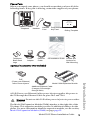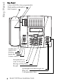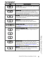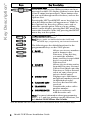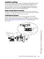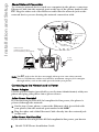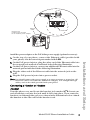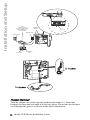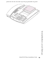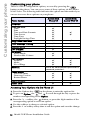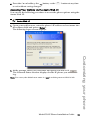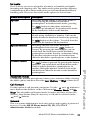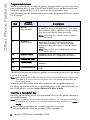
1
53i IP Phone
Installation Guide
41-001157-00
Rev 02
Software License Agreement
Aastra Telecom Inc., hereinafter known as "Seller", grants to Customer a
personal, worldwide, non-transferable, non-sublicenseable and non-exclusive, restricted use license to use Software in object form solely with the
Equipment for which the Software was intended. This Product may integrate programs, licensed to Aastra by third party Suppliers, for distribution
under the terms of this agreement. These programs are confidential and
proprietary, and are protected as such by copyright law as unpublished
works and by international treaties to the fullest extent under the applicable law of the jurisdiction of the Customer. In addition, these confidential
and proprietary programs are works conforming to the requirements of
Section 401 of title 17 of the United States Code. Customer shall not disclose to any third party such confidential and proprietary programs and
information and shall not export licensed Software to any country except in
accordance with United States Export laws and restrictions.
Customer's use of this software shall be deemed to reflect Customer's
agreement to abide by the terms and conditions contained herein. Removal
or modification of trademarks, copyright notices, logos, etc., or the use of
Software on any Equipment other than that for which it is intended, or any
other material breach of this Agreement, shall automatically terminate this
license. If this Agreement is terminated for breach, Customer shall immediately discontinue use and destroy or return to Seller all licensed software
and other confidential or proprietary information of Seller. In no event
shall Seller or its suppliers or licensors be liable for any damages whatsoever (including without limitation, damages for loss of business profits,
business interruption, loss of business information, other pecuniary loss, or
consequential damages) arising out of the use of or inability to use the software, even if Seller has been advised of the possibility of such damages.
Model 53i IP Phone Installation Guide iii
Software License Agreement
Customer agrees to not reverse engineer, decompile, disassemble or display Software furnished in object code form. Customer shall not modify,
copy, reproduce, distribute, transcribe, translate or reduce to electronic
medium or machine readable form or language, derive source code without the express written consent of the Seller and its Suppliers, or disseminate or otherwise disclose the Software to third parties. All Software
furnished hereunder (whether or not part of firmware), including all copies
thereof, are and shall remain the property of Seller and its Suppliers and
are subject to the terms and conditions of this agreement. All rights
reserved.
Table of Contents
Software License Agreement.................................................................... iii
Introduction .................................................................................................1
Phone Features ..................................................................... 1
Requirements ........................................................................ 1
About This Guide ................................................................... 2
Phone Parts ........................................................................... 3
Key Panel .....................................................................................................4
Key Description............................................................................................5
Installation and Setup .................................................................................7
Direct or Shared Network Connection................................... 7
Connecting to the Network and to Power ............................ 8
Power Adapter ....................................................................... 8
Connecting a Handset or Headset ........................................ 9
Desk or Wall Installation ..................................................... 11
Inserting the Key Card on your Phone ................................ 12
Customizing your phone.......................................................................... 14
Accessing Your Options via the Phone UI .......................... 14
Accessing Your Options via the Aastra Web UI ................. 15
IP Phone Features .....................................................................................17
Other Phone Features .............................................................................. 21
Adjusting the Volume .......................................................... 21
Status Lights (LEDs) ........................................................... 21
Call Timer ............................................................................ 21
Programmable keys ............................................................ 22
Creating a Speeddial Key .................................................... 22
Line/Call Appearance Keys ................................................. 23
Using a Headset with your Telephone ................................ 23
Model 536 Expansion Modules (536M) ...................................................25
Installing the 536M .............................................................. 25
v
Table of Contents
Language ............................................................................. 17
Time and Date ..................................................................... 17
Ring Tone/Tone Set ............................................................. 18
Clear Message Waiting ........................................................ 18
Contrast Level ..................................................................... 18
Live Dialpad.......................................................................... 18
Set Audio ............................................................................. 19
Call Forward ........................................................................ 19
Network ............................................................................... 19
Phone Status ....................................................................... 20
User Password .................................................................... 20
Phone Lock ............................................................................ 0
Table of Contents
Table of Contents
Troubleshooting Solutions ......................................................................28
Limited Warranty .......................................................................................29
vi
Introduction
Congratulations on your purchase of the Model 53i IP Phone! The 53i
communicates over an IP Network, allowing you to receive and place calls
in the same manner as a regular business telephone. The 53i is capable of
supporting the SIP protocol.
Phone Features
•
•
•
•
•
•
•
•
•
•
•
3-line LCD screen
6 top keys: 4 are programmable hard keys
3 call appearance lines with LEDs
Supports up to 9 call lines
Full-duplex speakerphone for handsfree calls
Headset support (modular connector)
Built-in two-port, 10/100 Ethernet ports - lets you share a connection
with your computer
Inline power support (based on 802.3af standard) which eliminates
power adapters.
AC power adapter (included)
Enhanced busy lamp fields*
Set paging*
*Availability of feature dependant on your phone system or service provider.
Requirements
• SIP-based IP PBX system or network installed and running with a SIP
account created for the 53i phone.
• Access to a Trivial File Transfer Protocol (TFTP), File Transfer Protocol
(FTP), Hypertext Transfer Protocol (HTTP) server, or Hyper Text Transfer Protocol over Secure Sockets Layer (SSL) (HTTPS).
• Ethernet/Fast Ethernet LAN (10/100 Mb)
• Category 5/5e straight through cabling
• Power source
For Ethernet networks that supply in-line power to the
phone (IEEE 802.3af):
-
Introduction
For power, use the Ethernet cable (supplied) to connect from the
phone directly to the network for power. (No 48v AC power
adapter required.)
For Ethernet networks that DO NOT supply power to the phone:
-
For power, use the 48V AC Power Adapter (included) to connect
from the DC power port on the phone to a power source.
or
-
(optional) - For power, use a Power over Ethernet (PoE) power
injector or a PoE switch. A PoE power injector is available as an
optional accessory from Aastra Telecom. Contact your
Administrator for more information.
Model 53i IP Phone Installation Guide
1
Introduction
About This Guide
This manual describes how to physically set up your new 53i. Not all
features listed are available by default and some may depend on your
phone system or service provider. Contact your system administrator if you
have any questions on what features and services are available to you
on your system. This guide complements the SIP IP Phone Aastra 53i,
55i, 57i, 57i CT Administrator Guide and the Aastra Model 53i User
Guide.
SIP IP Phone Aastra 53i, 55i, 57i, 57i CT Administrator Guide – is designed
for network administrators, system administrators, developers and
partners who need information on installing this product on an IP network.
Aastra Model 53i User Guide – explains the most commonly used IP
telephone features for an end user.
These guides along with release notes, system updates, etc. can be
downloaded from our Web site at www.aastratelecom.com/IPPhones.
2
Model 53i IP Phone Installation Guide
Phone Parts
When you unpack your phone, you should ensure that you have all of the
following items. If any part is missing, contact the supplier of your phone.
Wall Mount
Drilling Template
asdassa
asdadsda
Telephone
Telephone
Base Desk
Legs
Handset
Power
Adapter
Handset
Cord
Ethernet
Cable
Programmable
Key Card
Wall Mount
Drilling Template
53i Installation Guide Screws and
Anchors for
Wall Mounting
Optional Accessories (Not Included)
Model 536M Expansion Module
Additional Ethernet Cable
(Category 5/5e straight
through cable)
A PoE (Power over Ethernet) inline power injector supplies 48v power to
the 53i through the Ethernet Cable on pins 4 & 5 and 7 & 8.
Warning: Do not use this PoE inline power injector to power other
devices.
The Model 536 Expansion Module (536M) attaches to the right side of the
53i phone. This expansion module provides 36 additional softkeys for the
phone. For more information about the expansion module, see the section,
Model 536 Expansion Modules (536M) on page page 25.
Model 53i IP Phone Installation Guide
3
Introduction
PoE
(Power over Ethernet)
Inline Power Injector
Key Panel
Key Panel
6 keys with LEDs (4 are programmable
High quality speakerphone
HAC handset
Goodbye key
Options key
Hold key
Redial Key
Volume control
Navigational keys
3-line LCD screen
Message waiting lamp
Keypad
Speakerphone/headset toggle key
Mute key
3 call appearance lines
4
Model 53i IP Phone Installation Guide
Key Description*
Keys
Key Description
Goodbye key - Ends an active call. The Goodbye
key also exits an open list, such as the Options List,
without saving changes.
Options key - Accesses options to customize your
phone. Your System Administrator may have
already customized some of your settings. Check
with your System Administrator before changing
the administrator-only options.
Hold key - Places an active call on hold. To retrieve
a held call, press the call appearance button beside
the light that is flashing.
Redial key - Redials up to 100 previously dialed
numbers. Pressing the Redial key twice
simultaneously redials the last dialed number.
Volume control key - Adjusts the volume for the
handset, headset, ringer, and handsfree speaker.
See "Adjusting the Volume" on page 21 for more
information.
Line/Call Appearance key - Connects you to a line
or call. The Aastra 53i IP phone supports up to 3
line keys.
Mute key - Mutes the microphone so that your
caller cannot hear you (the light indicator flashes
when the microphone is on mute).
Model 53i IP Phone Installation Guide
5
Key Description*
Handsfree key - Activates Handsfree for making
and receiving calls without lifting the handset.
When the audio mode option is set, this key is used
to switch between a headset and the handsfree
speakerphone. See "Customizing your phone" on
page 14 for more information.
Key Description*
Keys
Key Description
Navigation keys - Pressing the UP and DOWN
arrow keys lets you view different status and text
messages on the LCD display (if there is more than
1 line of status/text messages). These buttons also
let you scroll through menu selections, such as the
Options List.
Pressing the LEFT and RIGHT arrow keys lets you
view the different line/call appearances. While in
the Options List, these keys allow you to exit or
enter the current option. When you are editing
entries on the display, pressing the LEFT arrow key
erases the character on the left; pressing the RIGHT
arrow key sets the option.
Programmable keys - 6 Top Keys: 4 are
programmable hard keys.
Note: Keys 1 and 2 are hardcoded as the SAVE and
DELETE keys, respectively, and cannot be altered.
The following are the default functions for the
programmable keys on the 53i IP phone:
1 - SAVE
(hardcoded)
2 - DELETE
(hardcoded)
3 - DIRECTORY
4 - CALLERS LIST
5 - TRANSFER
6 - CONFERENCE
Allows you to save numbers
and/or names to the
Directory. Using this key,
you enter the number,
name, and line (or speeddial
key) to record in the
Directory List.
Allows you to delete entries
from the Directory List and
Callers List. (Must enter the
Directory or Callers list and
select an entry, then press
twice to delete entry).
Displays up to 200 names
and phone numbers (stored
in alphabetical order)
Accesses the last 200 calls
received.
Transfers the active call to
another number
Begins a conference call
with the active call.
Note: For more information about programming
keys 3, 4, 5, and 6 to perform specific functions, see
the Aastra 53i IP Phone User Guide.
*See the Aastra 53i User Guide for more information about each of these keys.
6
Model 53i IP Phone Installation Guide
Installation and Setup
The 53i can be setup to share a network connection with another network
device. Power can be provided by the supplied power adapter or by an
802.3af compliant network power source or with a PoE inline power
injector (optional accessory). If your System Administrator has already
setup your phone, please refer to the 53i User Guide for call handling
information or contact your System Administrator.
Direct or Shared Network Connection
The phone can be set up as a direct network connection to the Ethernet
wall jack or as a shared network connection as a pass-through if connecting
the phone to a computer or another network device.
Direct Network Connection
Located at the top of the phone are two fully switched 10/100 Mbps
Ethernet cable ports. The port marked with LAN is used to connect the
phone to the network, as well as provide power to your phone (if required).
See "Connecting to the Network and to Power" on page 8 for more
information.
Power Adapter
Connection
Separate
Network
Jack
Ethernet
Cable
Installation and Setup
Network Jack
(if Inline power provided,
do not install the power adapter)
To Network
Power
Adapter
Other Network Devices
Model 53i IP Phone Installation Guide
7
Installation and Setup
Shared Network Connection
To connect a network device (such as a computer) to the phone, connect an
Ethernet Cable into the network port on the top of the phone marked with
PC. Plug the other end of the Ethernet cable into the network jack on the
network device you are sharing the network connection with.
Power Adapter
Connection
To Other
Network Device
Network Jack
(if Inline power provided,
do not install the power adapter)
To Network
Ethernet
Cables
Power
Adapter
Other Network Devices
Note: The PC jack on the 53i does not supply inline power onto other network
devices. All Ethernet cables used must be minimum category 5/5e straightthrough cables, such as the cable provided with your phone.
Connecting to the Network and to Power
Power Adapter
Use the power adapter (provided by your System Administrator) with your
phone and plug your phone into a power source.
Inline Power Provided
If your network provides 802.3af compliant in-line power, the phone is
powered through the network.
1. On the top of your phone, connect the Ethernet cable (provided with
your phone) into the network port marked with LAN.
2. Plug the other end of the Ethernet Cable directly into the network jack
on the wall.
Inline Power Not Provided
If your network does not provide 802.3af compliant in-line power, you have to
8
Model 53i IP Phone Installation Guide
Ethernet
Cable
To Network
Network Jack
(if Inline power provided,
do not install the power adapter)
install the power adapter or the PoE inline power supply (optional accessory).
Note: You should connect the power supply to a surge protector or power bar. All
Ethernet cables used must be minimum category 5/5e straight-through
cables, such as the cable provided with your phone.
Connecting a Handset or Headset
Handset
Turn the phone over and locate the handset jack marked j. Insert one
end of handset cord into the jack until it clicks into place. Then route the
handset cord through the groove as shown in the illustration below. Attach
the handset to the other end of the handset cord.
Model 53i IP Phone Installation Guide
9
Installation and Setup
1. On the top of your phone, connect the Ethernet cable (provided with
your phone) into the network port marked with LAN.
2. On the PoE power injector, plug the other end of the Ethernet cable into
the network jack marked as indicated in the following illustration.
3. On the PoE power injector, connect an additional Ethernet cable into the
network port as indicated in the following illustration.
4. Plug the other end of the Ethernet cable into the network jack on the
wall.
5. Plug the PoE power injector into a power outlet.
Installation and Setup
PoE
Power injector
(if Inline power or the
power adapter are
not provided)
Ethernet
Cables
To PoE
Network Jack
Power Outlet
To Phone
To Network
Jack
To Headset
To Handset
Headset (Optional)
Turn the phone over and locate the headset jack marked f. Insert the
headset cord into the jack until it clicks into place. Then route the headset
cord through the groove as shown in the above illustration.
10 Model 53i IP Phone Installation Guide
Desk or Wall Installation
Install on the Desk
The desk installation for the 53i IP phone consists of two legs that attach to
the back of the phone near the top corners. A total of four different
viewing angles allows users to personalize their phone viewing preference.
Attach each leg by inserting the tabs on the leg into the slots on the bottom
of the phone. There are three pair of leg slots on each corner of the phone;
each leg uses two pairs (1&2, or 2&3) giving two leg positions designating
different viewing angles. Furthermore, the legs can be reversed which
offer two additional viewing angles.
For a higher viewing angle, use the second and third slots from the top. For
a lower viewing angle, use the first and second slots from the top. Then
push the stand towards the phone until it snaps into place.
Installation and Setup
Three leg slot locations
for customizing the height
of the desk phone.
20.7 deg.
Incline Angle
23.3 deg.
Incline Angle
26.6 deg.
Incline Angle
30.9 deg.
Incline Angle
Total 4 Viewing Angles
Model 53i IP Phone Installation Guide
11
Installation and Setup
Install on the Wall
The 53i IP phone has two pre-drilled wall mounting holes on the back of
the phone. Using the provided wall mount drilling template, locate and
mark the position for the mounting screws on the wall. Depending on the
wall type, you may need to use wall anchors. Both the screws and wall
anchors are included with your phone.
Place the wall mount holes on the phone over the screw heads on the wall
and pull down to lock the phone in.
Wall Mount Holes
Note: You may wish to purchase a short Ethernet cable from a local supplier for a
wall installation. Also, if 802.3af compliant in-line power is not provided on
your network, and you are installing the 53i on a wall using a PoE in-line
power injector, you may also wish to use an equivalent flat Ethernet cable
rather than the one provided.
Inserting the Key Card on your Phone
This card contains the label identification spaces for 6 programmable keys.
1. Remove the clear plastic lens from the top front panel of the telephone
by gently pressing down on the lens and sliding upward.
2. Place the card into the programmable key card slot on the top front
panel of the telephone using the indentation of the plastic for alignment.
3. With one hand holding the label card in place, gently slide the clear
12 Model 53i IP Phone Installation Guide
plastic lens into the slots at the top of the programmable key panel.
Installation and Setup
Model 53i IP Phone Installation Guide
13
Customizing your phone
Customizing your phone
There is a list of configuration options, accessed by pressing the
button on the phone. You can access some of these options via the Aastra
Web UI also. The following table indicates the options and the method you
can use to access these options on your phone.
Access from
Phone UI
Access from
Aastra Web UI
Language
Time and Date
Time
Date
Time and Date Formats
Time Server
Time Zone
Daylight Savings Time
Ring Tones/Tone Sets
Clear Message Waiting
Contrast Level
Live Dialpad
Set Audio
Audio Mode
Headset Mic Volume
Call Forward
Number
Mode
No. of Rings
Phone Option
Network
This is an Administrator option that is
password protected..
Phone Status
Network Status
Firmware Version
Restart Phone
User Password
Phone Lock
Accessing Your Options via the Phone UI
1. Press the Options key
on the phone to enter the options list.
2. To go to an Option, use
and
to scroll through the list, or press the
number corresponding to the Option.
3. Press the Show softkey, the
button, or press the digit number of the
corresponding option to select an option.
4. Use the softkeys to change a selected option.
5. Press the Done softkey at any time to exit the option and save the change.
14 Model 53i IP Phone Installation Guide
6. Press the Cancel softkey, the
button, or the N button at any time
to exit without saving changes.
Accessing Your Options via the Aastra Web UI
You can use the following procedure to access the phone options using the
Aastra Web UI.
Aastra Web UI
1. Open your web browser, enter the phone’s IP address or host name into
the address field and press <Enter>.
The following logon screen displays.
Note: For a user, the default user name is “user” and the password field is left
Model 53i IP Phone Installation Guide
15
Customizing your phone
2. At the prompt, enter your username and password and click
.
The Network Status window displays for the IP phone you are accessing.
Customizing your phone
blank..
3. You can logout of the Aastra Web UI at any time by clicking Log Off.
The side menu options that display in the Network Status window are
dependant on whether you log in as an Administrator or User. A longer list
of options display in the side menu for an Administrator.
Reference
For more information about using the side menu options in the Aastra Web
UI, see the Aastra Model 53i IP Phone User Guide or the
Aastra 53i, 55i, 57i, 57i CT IP Phone Adminsitrator Guide.
16 Model 53i IP Phone Installation Guide
IP Phone Features
Language
Select a language that you would like your phone to use for displaying
prompts and menus.
Note: Supported languages may vary depending on configuration. Contact your
Network Administrator for list of available languages.
Time and Date
Use these options to set the local time on the phone. Depending upon the
configuration, time set here may be overwritten by the time on your phone
system. If you are having problems with this, contact your Network
Administrator.
• Time Server
Talk to your Network Administrator before making changes to this option.
If the Time Server option is enabled, the display shows the IP address
where the phone is getting time and date information from on the
Network. Whenever the phone starts up, it will automatically
attempt to find the Time Server. If the Time Server is not found and
unknown to the phone, the IP address will display as 0.0.0.0, and the
time and date in the main screen displays the equivalent of “12:00 am
Jan. 1st 2000". If the Time Server option is disabled, the display shows
“Network Time Disabled”. You can set the time and date manually on
your phone.
• Set Time
This option shows the Network time, if the Time Server option is
enabled. It also allows you to set the time manually.
Note: if you set the time manually, the phone will not try to synchronize the time with a
timeserver until the next time it is restarted.
• Set Date
This option shows the Network date, if the Timeserver option is
enabled. It also allows you to enter the date manually.
Note: if you set the date manually, the phone will not synchronize the date with a
timeserver until the next time it is restarted.
• Date Format
Choose from a list of formats for how the date displays on your phone.
• Time Zone
Choose your current time zone. Select your country by scrolling through
a list, or by entering the country code (i.e., CA, US), then pick from the
time zone list for that country.
• Daylight Savings
This option allows you to specify daylight savings.
Model 53i IP Phone Installation Guide
17
IP Phone Features
• Time Format
Select a time format for how time displays on your phone (12h or 24h
clock).
IP Phone Features
Ring Tone/Tone Set
Use these options to set the preference of ring tone and call progress tones
for your phone.
• Ring Tone
Press the Change softkey to select one of the five ring tones or silent. Use
the volume bar to increase or decrease the ringer volume level.
• Tone Set
Press the Change softkey to select one of the seven predefined tone sets
for the phone to play country specific call progress tones such as dial
tone, ringing tone, busy tone, congestion tone, call waiting tone, and
ringing cadence.
Clear Message Waiting
To clear the Message Waiting Light, select the Clear softkey. The light will
flash again when there are new messages waiting.
Contrast Level
Use these options to set the preference of contrast level for your phone.
• Contrast Level
Use the Change softkey to cycle through eight contrast settings, which
brighten or darken the display.
Live Dialpad*
This option turns the Live Dial Pad mode ON or OFF. With live dial pad
ON, the 53i IP phone automatically dials out and turns ON Handsfree
mode as soon as a dial pad key or softkey is pressed. With live dial pad
OFF, if you dial a number while the phone is on-hook, lifting the receiver
or pressing the
initiates a call to that number. Press the Change
softkey to turn ON or OFF the dial pad mode.
*Availability of feature dependant on your phone system or service provider.
18 Model 53i IP Phone Installation Guide
Set Audio
The 53i allows you to use a handset, a headset, or handsfree to handle
incoming and outgoing calls. The audio mode option provides different
combinations of these three methods to provide maximum flexibility in
handling calls. There are four audio mode options to choose from:
Audio Mode Option Description
This is the default setting. Calls can be made or
received using the handset or handsfree
speakerphone. In handset audio mode, pressing
the
button on the phone switches to
handsfree speakerphone. In Speaker audio mode,
lift the handset to switch to the handset.
Headset
Choose this setting if you want to make or receive
all calls using a handset or headset. Calls can be
switched from the handset to headset by pressing
the
button on the phone. To switch from the
headset to the handset, lift the handset.
Speaker/Headset
Incoming calls are sent to the handsfree
speakerphone first when the
button is
pressed. By pressing the button again, you can
switch back and forth between the handsfree
speakerphone and the headset. At anytime, lifting
the handset switches back to the handset from
either the handsfree speakerphone or the headset.
Headset/Speaker
Incoming calls are sent to the headset first when
the
button is pressed. By pressing the button
again, you can switch back and forth between the
headset and the handsfree speakerphone. At
anytime, lifting the handset switches back to the
handset from either the headset or the handsfree
speakerphone.
Headset Mic Volume
To adjust the headset microphone volume, press Advanced after selecting
the audio option, and then select the Low, Medium, or High volume level.
Call Forward
Use this option to call forward your phone. Use the
and
buttons to
move between the fields to set the call forward Number, Mode, and No.
Rings. The selectable call forward mode includes: All, Busy, NoAns (No
Answer), BusyNoAns (Busy No Answer), or Off; this is selected via the
and
buttons.
Network
This is a system administrator level-only option, and requires a password
to access. See the SIP IP Phone Aastra 53i, 55i, 57i, 57i CT
Administrator Guide for details.
Model 53i IP Phone Installation Guide
19
IP Phone Features
Speaker
IP Phone Features
Phone Status
This option allows you to:
• View your network status including your phone’s IP and MAC address
• View your firmware version
• Restart your phone
There is also a system administrator level-only option to reset the phone to
factory default settings. See your system administrator for details.
User Password
Use this option to change your user password. Valid values for entering a
password are 0 to 4294967295 (integers only; symbols and alpha characters
are not allowed). Default password is an empty string "" (field is blank).
Phone Lock
Use this option to lock the phone from unauthorized users. When the
phone is locked, users are unable to dial from the phone unless it has been
unlocked. To unlock the phone, press the
button and enter either
the user or administrator password.
Note: While the phone is locked, only emergency number dialing is permitted. The
default permissible emergency numbers are 911, 999, 112, and 110; this is configurable via the WebUI or configuration file.
Hint: To quickly lock your phone, press the
key.
20 Model 53i IP Phone Installation Guide
button followed by the
Other Phone Features
Adjusting the Volume
Pressing the volume button
speaker, and ringer volume.
adjusts the receiver, headset,
• To adjust the ringer volume, leave the handset in the cradle and press
the volume button
while there is no active call. There are 10
settings for the ringer including Off — the display will temporarily
indicate the current ringer volume setting.
• To adjust the handset volume, lift the handset and press the volume button
while the handset is off hook. The handset will remain at
this volume until it is adjusted again.
• To adjust the headset volume, press the volume button
while
the headset is activated (activate the headset by pressing
; ensure
headset audio mode is set). The headset will remain at this volume until
it is adjusted again.
• To adjust the speaker volume, press the volume button
while
the speaker is activated (activate the speaker by pressing
; ensure
handsfree speakerphone audio mode is set). The speaker will remain at
this volume until it is adjusted again.
Status Lights (LEDs)
The speaker LED, beside the
key, and the Message Waiting
Indicator (MWI) LED, on the top right of your phone, provide visual
indications of your phone’s status.
Speaker LED Status
Description
ON solid
Indicates a call is on Handsfree (speakerphone)
Slow Flash
Indicates you are using the headset.
Rapid Flash
Indicates the call is muted. Press
call off mute.
to take the
Message Waiting Indicator (MWI)
MWI LED Status
Description
Slow Flash
Indicates you have a message(s).
Rapid Flash
Indicates you have an incoming call.
Even Flash
Indicates one or more calls are on hold.
Call Timer
• When you make or answer a call, the Timer shows the elapsed time of
the call.
Model 53i IP Phone Installation Guide
21
Other Phone Features
Speaker LED
Other Phone Features
Programmable keys
There are 6 hard keys on the 53i phone, located at the top, left of the front
panel display. Keys 1 and 2 (SAVE and DELTE keys) are hardcoded and
cannot be changed. Keys 3, 4, 5, and 6 are programmable keys.
The following are the default functions for the programmable keys on the
53i IP phone.
Key
1
Default
Function
SAVE
(hardcoded)
Description
Allows you to save numbers and/or names
to the Directory. Using this key, you enter
the number, name, and line (or speeddial
key) to record in the Directory List.
Note: The SAVE key is hardcoded and cannot
be altered.
2
DELETE
(hardcoded)
Allows you to delete entries from the
Directory List and Callers List. (Must
enter the Directory or Callers list and
select an entry, then press twice to delete
entry).
Note: The DETETE key is hardcoded and cannot be altered.
3
DIRECTORY
Displays up to 200 names and phone
numbers (stored in alphabetical order).
4
CALLERS LIST
Accesses the last 200 calls received.
5
TRANSFER
Transfers the active call to another
number.
6
CONFERENCE
Begins a conference call with the active
call.
These keys can also be set up to quickly access features such as Call return
(*69) or Voicemail.
Note: Quick access features like Call return and Voicemail must first be configured on
your PBX in order to work on your phone. See your system administrator for
more information.
You must use the Aastra Web UI to configure the programmable key.
For more information about programming keys with other functions on
the 53i IP phone, see the Aastra Model 53i User Guide.
Creating a Speeddial Key
Pressing and holding down a programmable key on the phone initiates a
speeddial feature.
Note: When creating a speeddial key from the IP Phone UI, you must select a programmable key that has no preassigned function (key must be set to none or
empty.
1. Press a programmable key on the keypad for 3 seconds.
A screen displays with the prompt, "Enter number>".
22 Model 53i IP Phone Installation Guide
2. Enter a phone number or extension to assign to that speeddial key.
The following example illustrates the screen display:
Speeddial
Enter number> 3456
After entering the number, the prompt, "Use Save to end" displays on
the screen.
3456
Use Save to end
3. Press
(Key 1) to save the number as a speeddial key.
By default, the phone automatically assigns the speeddial key to line 1 if
available. You can use the
and
to change the speeddial information to a different line if required.
Line: 1
Change
Use Save to end
(Key 1) to save the speeddial key to the line specified.
Other Phone Features
4. Press
Line/Call Appearance Keys
The 53i has 3 hard/line call appearance keys each with a corresponding
status light. Additional line call appearances may also be set up on your
phone as programmable keys.
These line call appearance buttons and lights represent physical lines or
calls for your extension. By pressing a line call appearance button, you
connect to the line or a call it represents. The line call appearance light
indicates the status of that line or call.
When the phone is taken off-hook, the phone will automatically select a
line for you.
Line Call Appearance LED Status
Description
OFF
Indicates idle line or no call
activity
Rapid Flash
Indicates ringing on the line.
Slow Flash
Indicates a call is on hold.
For more information about the Line Call Appearance keys, see the
Aastra Model 53i User Guide.
Using a Headset with your Telephone
Model 53i IP Phone Installation Guide
23
Other Phone Features
The 53i accepts headsets through the modular jack on the back of the
phone. Contact your telephone equipment retailer or distributor to
purchase a compatible headset. A non-amplified headset is required.
Customers should read and observe all safety recommendations
contained in headset operating guides when using any headset.
Note: For best headset performance, Aastra recommends non-amplified headset
equipped with modular connector.
Making and Receiving Calls using a Headset
1. Ensure that you have selected a headset audio mode by accessing the
Options menu. See the section "Customizing your phone" on page 14
for detailed information.
2. Plug the headset into jack.
3. Press the
key to obtain dial tone or answer an incoming call.
Depending on the audio mode selected from the Options menu, dial
tone or an incoming call will be received on either the headset or the
handsfree speakerphone.
4. Press the Nkey to end the call.
24 Model 53i IP Phone Installation Guide
Model 536 Expansion Modules (536M)
The 53i IP Phone offers an optional Expansion Module that attaches to the
right side of the phone to provide additional softkeys.
•
•
•
•
Busy Lamp Fields (BLFs) (maximum of 50)
Speedial
Shared Call Appearance
Phone Lock
Note: For more information about configuring the expansion module softkeys with
these functions, see the Aastra 53i SIP IP Phone User Guide.
Each key provides an LED for indicating call status. The 536M provides a
paper label for convenient key labeling.
Additional 536M modules (up to 3 total modules) can be piggy-backed to
an existing module providing an additional 108 softkeys to the phone. You
connect the additional modules to the right side of an existing module. The
following figure illustrates the addition of multiple 536M modules on the
53i IP Phone.
You can configure the softkeys using the Aastra Web UI.
For more information about using the expansion modules on the 53i IP
phone, see the Aastra 53i SIP IP Phone User Guide.
Installing the 536M
Model 53i IP Phone Installation Guide
25
Model 536 Expansion Modules (536M)
The 536M provides 36 additional softkeys on a 53i IP Phone. The softkeys
support the following features:
Model 536 Expansion Modules (536M)
On the 536M, there are 18 softkeys in each column (totaling 36 keys) on the
keypad.
536M
The module connects to the right side of the 53i IP phone via an RJ-45
connector.
Connecting the Expansion Modules to Your Phone
Use the following procedure to connect the 536M to your 53i IP phone.
1. Turn your phone over to show the bottom of the phone.
2. Turn the expanstion module over to show the bottom of the module.
3. Connect one end of the RJ-45 cable to the RJ-45 port on the back of your
phone as indicated in the illustration below.
Back of Expansion
Back of Phone
Module
RJ-45 Connectors
26 Model 53i IP Phone Installation Guide
4. Connect the other end of the RJ-45 cable to the RJ-45 port on the back of
the expansion module as indicated in the illustration above.
5. Turn over both units to sit face up on the desk with the expansion module sitting flush against the right side of the phone.
Note: Install additional modules as applicable using additional RJ-45 cables. You
must attach any additional module to the right side of an existing module
(piggy-backed) as shown in the following illustration.
Model 536 Expansion Modules (536M)
For more information about setting the softkeys, see the
Aastra Model 53i User Guide.
Model 53i IP Phone Installation Guide
27
Troubleshooting Solutions
Troubleshooting Solutions
Why is the light not coming on with a new Voice Mail Message?
Your phone system or service provider must provide “Visual” Message
Waiting service for this function to work. Check with your system
administrator for more information.
Why is my handset not working?
Check to ensure that the handset cord is fully connected to both the phone
and handset. See the section "Connecting a Handset or Headset" on
page 9 for information.
Why is my speakerphone not working?
If you press
and the speaker light flashes and you do not hear dial
tone, the Set Audio option has been used to set up the phone for headset
use; press
a second time. If the light goes out, the phone is set up to
be used only with a headset or handset. If the light stays on steady and you
hear dial tone, you can alternate between the speakerphone and the
headset by pressing
. See the section, "Set Audio" on page 19 for
instructions on how to change the Set Audio feature.
Why is my display blank?
Ensure that power is being provided to your phone. If your Network does
not provide Inline power over Ethernet, you can obtain an additional
accessory, the a PoE inline power injector, to provide power over
Ethernet locally to your phone. See the section "Connecting to the
Network and to Power" on page 8 for details.
Why can I only see 1 option when the installer or user guide says there
are more?
The telephone screen will only show 1option at a time. To see more, press
the down arrow button
.
Why does the telephone wobble?
Make sure the cords are routed properly through the back of the phone, as
indicated in the section, "Connecting a Handset or Headset" on page 9.
Check that the leg stands have been properly snapped into place. Since
the legs can be oriented in two different ways and in two different positions
to offer four different phone viewing angles, check that both legs are
oriented in the same direction and in the same position on either side of
the phone.
What is a programmable key?
There are 6 top hard keys (programmable up to 6 functions), located at the
top of the front panel. These are keys that you can set to perform specific
functions and access enhanced services provided by third parties (for
example, XML applications). See the section "Programmable keys" on
page 22 or refer to your Aastra Model 53i User Guide. for more
information.
28 Model 53i IP Phone Installation Guide
Limited Warranty
Aastra Telecom warrants this product against defects and malfunctions during a
one (1) year period from the date of original purchase. If there is a defect or
malfunction, Aastra Telecom shall, at its option, and as the exclusive remedy, either
repair or replace the telephone set at no charge, if returned within the warranty
period.
If replacement parts are used in making repairs, these parts may be refurbished, or
may contain refurbished materials. If it is necessary to replace the telephone set, it
may be replaced with a refurbished telephone of the same design and color. If it
should become necessary to repair or replace a defective or malfunctioning
telephone set under this warranty, the provisions of this warranty shall apply to the
repaired or replaced telephone set until the expiration of ninety (90) days from the
date of pick up, or the date of shipment to you, of the repaired or replacement set,
or until the end of the original warranty period, whichever is later. Proof of the
original purchase date is to be provided with all telephone sets returned for
warranty repairs.
Exclusions
Aastra Telecom does not warrant its telephone sets to be compatible with the
equipment of any particular telephone company. This warranty does not extend to
damage to products resulting from improper installation or operation, alteration,
accident, neglect, abuse, misuse, fire or natural causes such as storms or floods,
after the telephone is in your possession.
Aastra Telecom shall not be liable for any incidental or consequential damages,
including, but not limited to, loss, damage or expense directly or indirectly arising
from the customers use of or inability to use this telephone, either separately or in
combination with other equipment. This paragraph, however, shall not apply to
consequential damages for injury to the person in the case of telephones used or
bought for use primarily for personal, family or household purposes.
This warranty sets forth the entire liability and obligations of Aastra Telecom
with respect to breach of warranty, and the warranties set forth or limited herein
are the sole warranties and are in lieu of all other warranties, expressed or implied,
including warranties or fitness for particular purpose and merchantability.
Should the set fail during the warranty period;
In North America, please call 1-800-574-1611 for further information.
Outside North America, contact your sales representative for return instructions.
You will be responsible for shipping charges, if any. When you return this
telephone for warranty service, you must present proof of purchase.
After Warranty Service
Aastra Telecom offers ongoing repair and support for this product. This service
provides repair or replacement of your Aastra Telecom product, at Aastra
Telecom's option, for a fixed charge. You are responsible for all shipping charges.
For further information and shipping instructions;
In North America, contact our service information number: 1-800-574-1611.
Outside North America, contact your sales representative.
Note: Repairs to this product may be made only by the manufacturer and its authorized
agents, or by others who are legally authorized. This restriction applies during and after
the warranty period. Unauthorized repair will void the warranty.
Model 53i IP Phone Installation Guide
29
Limited Warranty
Warranty Repair Services
Index
Numerics
K
536M 25
53i line settings 23
key card 12
Key Description 4
audio, setting 19
language 17
lights or LEDs
MWI 21
speaker 21
status 21
locking the phone 20
A
L
C
call forward 19
call timer 21
Connecting
Direct Network 7
Handset or Headset 9
Shared Network 8
To Power 8
To the Network 8
contrast level, setting 18
Customizing your phone 14
D
setting date 17
setting format 17
daylight savings 17
delete key 6, 22
dialpad, live 18
N
O
Optional Accessories 3
P
E
Ethernet Cable 8
Ethernet wall jack 7
expansion module, 536M 3, 25
expansion, module installing 25
H
Handset, connecting 9
headset mode 19
Headset, connecting 10
headset, making and receiving calls
with 24
headset/speaker mode 19
phone features 1
phone parts 3
phone status 20
PoE 3
power adapter 8
programmable keys 22
R
Requirements 1
ring tone, setting 18
S
save key 6, 22
speaker mode 19
speaker/headset mode 19
speeddial key, creating from phone
keypad 22
Stand Installation 11
T
Index
indicator light 21
inline power 8
Installation 5
installation
desk 11
Installation and Setup 7
Introduction 1, 31
message waiting, clearing 18
microphone volume, headset 19
MWI (message waiting indicator)
21
network
configuration settings for 19
network connection, direct 7
network connection, shared 8
date
I
M
time
setting format 17
setting time 17
setting time server 17
Model 53i IP Phone Installation Guide
Index-1
Index
Index
setting time zone 17
tone set, setting 18
U
user password 20
V
volume, adjusting 21
W
wall installation 12
warranty, limited 31
Web UI, using 15
Index-2
Model 53i IP Phone Installation Guide
If you’ve read this owner’s manual and consulted the Troubleshooting section
and still have problems, please visit our Web site at www.aastra.com, or call
1-800-574-1611 for technical assistance.
© Aastra Telecom Inc. 2007 41-001157-00 Rev 02