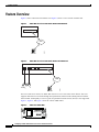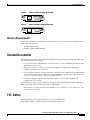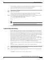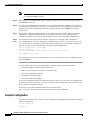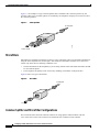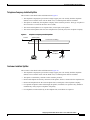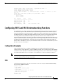
1
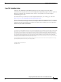
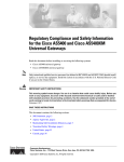
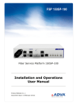
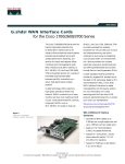
Configuring an ADSL WAN Interface Card on
Cisco 1700 Series Routers
This document describes asymmetric digital subscriber line (ADSL) one-port wide area network (WAN)
interface cards (WICs). These cards provide ADSL high-speed digital data transfer between a single
customer premises equipment (CPE) subscriber and a central office.
ADSL WICs are available in three variations: ADSL over POTS (WIC-1ADSL), ADSL over POTS with
Dying Gasp support (WIC-1ADSL-DG), and ADSL over ISDN with DyingGasp support
(WIC-1ADSL-I-DG). The ADSL over POTS WICs are commonly used to provide ADSL services over
ordinary telephone lines. The ADSL over ISDN WIC is used to provide ADSL services in those areas of
the world which have extensive ISDN backbones already in place.
This document contains the following sections:
•
Feature Overview, page 2
•
Related Documents, page 3
•
FCC Notice, page 3
•
Safety Warnings, page 4
•
Connecting an ADSL WIC to the Network, page 6
•
Configuring the ADSL Interface, page 7
•
Using POTS Splitters and Microfilters, page 13
•
Configuring Quality of Service Parameters, page 17
•
Configuring the SCC Clock Rate, page 28
•
Configuring FRF.5 and FRF.8 Internetworking Functions, page 29
•
Obtaining Documentation, page 30
•
Obtaining Technical Assistance, page 31
Corporate Headquarters:
Cisco Systems, Inc., 170 West Tasman Drive, San Jose, CA 95134-1706 USA
Copyright © 2002. Cisco Systems, Inc. All rights reserved.
Feature Overview
Feature Overview
Figure 1 shows a data network with the card. Figure 2 shows a voice network with the card.
Figure 1
ADSL WIC in a Cisco 1700 Series Router Data Network
ADSL WIC
AAL5
41852
ADSL
DSLAM
Figure 2
ADSL WIC in a Cisco 1700 Series Router Voice Network
ADSL WIC
AAL5
ADSL
DSLAM
41851
Analog phones
On Cisco 1700 series routers, an ADSL WIC fits into a Cisco 1700 series router chassis. The card
supports data and voice networks through the asynchronous transfer mode (ATM) protocol with the
AAL5 format. ATM quality of service (QoS) for permanent virtual circuits (PVCs) is also supported.
Figure 3, Figure 4, and Figure 5 show the various ADSL WICs.
Figure 3
ADSL over POTS WIC
ADSL
CD LP OK
WIC
1ADSL
38913
SEE MANUAL
BEFORE INSTALLATION
Configuring an ADSL WAN Interface Card on Cisco 1700 Series Routers
2
OL-3317-03
Related Documents
SEE MANUAL
BEFORE INSTALLATION
ADSL
Figure 5
WIC
1ADSL DG
CD LP OK
88862
ADSL over POTS with Dying Gasp WIC
ADSL over ISDN with Dying Gasp WIC
SEE MANUAL
BEFORE INSTALLATION
ADSL
CD LP OK
WIC
1ADSL IDG
88863
Figure 4
Memory Requirements
The memory requirements for running the full-featured Cisco 1700 router encryption images with the
ADSL WICs are as follows:
•
16 MB of Flash memory
•
64 MB of dynamic RAM (DRAM)
Related Documents
The following documents provide additional information about installing and configuring ADSL WICs
and configuring the router software:
•
Cisco WAN Interface Cards Hardware Installation Guide—provides installation information on the
ADSL WAN interface card.
•
Regulatory Compliance and Safety Information document—provides safety warnings and
compliance information for your router.
•
Cisco 827 Routers Software Configuration Guide—provides router configurations for ATM data and
voice networks for the Cisco 827-4V router. These configurations will also work for the Cisco 1720,
1721, 1751, and 1760 routers, except for the dialer interface.
•
Cisco IOS configuration guides and command references—provides IOS commands and
configurations for your router.
The following document provides additional information about configuring QoS features and Frame
Relay Forum (FRF) internetworking functions on ADSL WICs.
•
Enhanced Voice and QoS for ADSL and G.SHDSL on Cisco 1700 Series, Cisco 2600 Series, and
Cisco 3600 Series Routers
FCC Notice
The following FCC Notice applies to the Cisco 1700 series ADSL WIC:
WIC-1ADSL complies with FCC part 68 FCC ID:5B1USA-42011-DL-N
Configuring an ADSL WAN Interface Card on Cisco 1700 Series Routers
OL-3317-03
3
Safety Warnings
Safety Warnings
Safety warnings appear throughout this publication in procedures that can harm you if they are
performed incorrectly. A warning symbol precedes each warning statement.
Warning Conventions
Warning
This warning symbol means danger. You are in a situation that could cause bodily injury. Before you
work on any equipment, be aware of the hazards involved with electrical circuitry and be familiar
with standard practices for preventing accidents. To see translations of the warnings that appear in
this publication, refer to the Regulatory Compliance and Safety Information document that
accompanied this device.
Power Supply Warnings
The following warnings apply when you are installing a card or working with the power supply:
Warning
Read the installation instructions before you connect the system to its power source.
Warning
Only trained and qualified personnel should be allowed to install or replace this equipment.
Warning
Ultimate disposal of this product should be handled according to all national laws and regulations.
Warning
When installing or replacing the unit, the ground connection must always be made first and
disconnected last.
Warning
This equipment must be grounded. Never defeat the ground conductor or operate the equipment in the
absence of a suitable installed ground conductor. Contact the appropriate electrical inspection
authority or an electrician if you are uncertain that suitable grounding is available.
Warning
Use copper conductors only.
Warning
Blank faceplates and cover panels serve three important functions: they prevent exposure to
hazardous voltages and currents inside the chassis; they contain electromagnetic interference (EMI)
that might disrupt other equipment; and they direct the flow of cooling air through the chassis. Do not
operate the system unless all cards, faceplates, front covers, and rear covers are in place.
Configuring an ADSL WAN Interface Card on Cisco 1700 Series Routers
4
OL-3317-03
Safety Warnings
The following warning applies when this product is used in Australia.
Warning
This equipment must be installed and maintained by service personnel as defined by AS/NZS 3260.
Incorrectly connecting this equipment to a general purpose outlet could be hazardous. The
telecommunications lines must be disconnected 1) before unplugging the main power connector or 2)
while the housing is open, or both.
Electrical Warnings
The following warnings apply when you are working with electricity:
Warning
Before working on equipment that is connected to power lines, remove jewelry (including rings,
necklaces, and watches). Metal objects will heat up when connected to power and ground and can
cause serious burns or weld the metal object to the terminals.
Warning
Before opening the unit, disconnect the telephone-network cables to avoid contact with
telephone-network voltages.
Warning
Do not work on the system or connect or disconnect cables during periods of lightning activity.
Warning
Do not use this product near water; for example, near a bath tub, wash bowl, kitchen sink or laundry
tub, in a wet basement, or near a swimming pool.
Warning
Never install telephone jacks in wet locations unless the jack is specifically designed for wet
locations.
Warning
Never touch uninsulated telephone wires or terminals unless the telphone line has been
disconnected at the network interface.
Warning
Avoid using a telephone (other than a cordless type) during an electrical storm. There may be a remote
risk of electric shock from lightning.
Warning
To report a gas leak, do not use a telephone in the vicinity of the leak.
Configuring an ADSL WAN Interface Card on Cisco 1700 Series Routers
OL-3317-03
5
Connecting an ADSL WIC to the Network
Warning
Do not touch the power supply when the power cord is connected. For systems with a power switch,
line voltages are present within the power supply even when the power switch is OFF and the power
cord is connected. For systems without a power switch, line voltages are present within the power
supply when the power cord is connected.
Follow these guidelines when working on equipment powered by electricity:
•
Locate the emergency power-off switch in the room in which you are working. Then, if an electrical
accident occurs, you can quickly turn off the power.
•
Before working on the router, turn off power to the router, and unplug the power cord.
•
Disconnect all power before doing the following:
– Installing or removing a router chassis
– Working near power supplies
•
Do not work alone if potentially hazardous conditions exist.
•
Never assume that power is disconnected from a circuit. Always check.
•
Look carefully for possible hazards in your work area, such as moist floors, ungrounded power
extension cables, and missing safety grounds.
If an electrical accident occurs, proceed as follows:
•
Use caution; do not become a victim yourself.
•
Turn off power to the router.
•
If possible, send another person to get medical aid. Otherwise, determine the condition of the victim,
and then call for help.
•
Determine whether the victim needs rescue breathing or external cardiac compressions; then take
appropriate action.
Preventing Electrostatic Discharge Damage
Electrostatic discharge (ESD) can damage equipment and impair electrical circuitry. It can occur when
printed circuit cards are improperly handled and can result in complete or intermittent failures. Always
follow ESD prevention procedures when removing and replacing cards. Ensure that the router chassis is
electrically connected to earth/ground. Wear an ESD-preventive wrist strap, ensuring that it makes good
skin contact. Connect the clip to an unpainted surface of the chassis frame to safely channel unwanted
ESD voltages to ground. To guard against ESD damage and shocks, the wrist strap and cord must be used
properly. If no wrist strap is available, ground yourself by touching the metal part of the chassis.
Caution
For safety, periodically check the resistance value of the antistatic strap, which should be between 1
and 10 megohms (Mohms).
Connecting an ADSL WIC to the Network
For this connection, use a standard lavender RJ-11 cable.
Configuring an ADSL WAN Interface Card on Cisco 1700 Series Routers
6
OL-3317-03
Configuring the ADSL Interface
Note
If you are connecting a Cisco 1700 series router with an ADSL WIC to an RJ-11 wall jack that has
the ADSL pair wired for pins 2 and 5, you must use the lavender crossover cable with the blue stripe.
The crossover cable is orderable as a spare.
The following steps tell how to connect the card, using the standard lavender RJ-11 cable; the steps also
apply to the lavender crossover cable with the blue stripe.
Step 1
Confirm that router power is still turned off.
Step 2
Connect one end of the cable (RJ-11) to the ADSL port on the card.
Step 3
Connect the other end of the cable to the wall jack (RJ-11) at your site, as shown in Figure 6.
Figure 6
Step 4
Connecting an ADSL WIC to a Wall Jack
Turn on power to the router.
The following warning applies to routers that use a DC power supply:
Step 5
To connect the card to the network, you must configure the ADSL card in the router to the no shutdown
state. Enter the no shut command in the router configuration. Verify that the CD LED comes on,
indicating that the card is connected to the network.
Configuring the ADSL Interface
Whenever you install a new WIC, or if you want to change the configuration of an existing interface, you
must configure the interface. If you replace a card that was already configured, the router recognizes it
and brings up the interface in the existing configuration.
Before you configure an interface, have the following information available:
•
Protocols you plan to route on the new interface
•
IP addresses, subnet masks, network numbers, zones, virtual path identifier/virtual channel
identifier (VPI/VCI) number(s), or other information related to the routing protocol
Configuring an ADSL WAN Interface Card on Cisco 1700 Series Routers
OL-3317-03
7
Configuring the ADSL Interface
Timesaver
Obtain this information from your system administrator or network plan before you begin router
configuration.
You can configure the new interface and other router parameters by using any of the following methods:
•
Configuration Mode (manual configuration)—recommended if you are familiar with IOS
commands. Enter the commands at the prompt.
•
AutoInstall (automatic installation)—recommended if another router running IOS software is
installed on the network. This configuration method must be coordinated in advance by someone
with experience using IOS software, such as the network administrator.
•
System Configuration Dialog (Setup facility)—recommended if you are not familiar with IOS
commands. You are prompted for each response.
These procedures are explained in the following sections. To change the settings shown in the examples,
and for further information, refer to the IOS configuration guides and command references. If you have
questions or need help, see the section “Obtaining Technical Assistance” later in this document.
Default Commands
The IOS software provides the following default configurations for ADSL-specific parameters.
The following default command sets the ADSL operating mode:
dsl operating-mode auto
The following command sets the ATM virtual circuit-per-virtual path (vc-per-vp) configuration for the
router:
atm vc-per-vp 256
Defaults for WIC-1ADSL-I-DG
For the WIC-1ADSL-I-DG, the default command operating-mode auto sets the carrier tone range from
33 to 56 to meet the requirements of the Deutsche Telekom U-R2 specification.
Alternately, to set the carrier tone range from 29 to 48, use the command
dsl operating-mode auto tone low
This command, dsl operating-mode auto tone low, is not available on the WIC-1ADSL or
WIC-1ADSL-DG.
Configuration Mode
You can configure the interfaces on your ADSL WIC manually by entering IOS commands on the
command line. This method, called configuration mode, provides the greatest power and flexibility.
For further information about these commands, refer to the IOS configuration guides and command
references.
Configuring an ADSL WAN Interface Card on Cisco 1700 Series Routers
8
OL-3317-03
Configuring the ADSL Interface
Before you begin, disconnect all WAN cables from the router to keep it from running the AutoInstall
process. The router tries to run AutoInstall whenever you power it on if there is a WAN connection on
both ends and the router does not have a valid configuration file stored in NVRAM (for instance, when
you add a new interface). It can take several minutes for the router to determine that AutoInstall is not
connected to a remote Transmission Control Protocol/Internet Protocol (TCP/IP) host.
To enter configuration mode, follow this procedure:
Step 1
Connect a console to the router. If you need instructions for connecting a console, refer to the
installation chapter of your router installation and configuration guide. Power up the router.
Step 2
If the current configuration is no longer valid, after about one minute you see the following prompt:
Would you like to enter the initial dialog? [yes]:
Enter no. You now enter the normal operating mode of the router.
Note
Step 3
If the current configuration is valid, you enter the normal operating mode automatically.
After a few seconds, you see the user EXEC prompt. Type enable and the password to enter enable
mode:
Router> enable
Password:
Configuration changes can be made only in enable mode. The prompt changes to the privileged EXEC
(enable) prompt (Router#):
Router#
Step 4
Enter the config terminal command to enter configuration mode:
Router# config terminal
Router(config)#
The router enters global configuration mode, indicated by the Router(config)# prompt.
Step 5
If you have not configured the router before or want to change the configuration, you can configure
global parameters, passwords, network management, and routing protocols. In this example, IP routing,
AppleTalk routing, and Internetwork Packet Exchange (IPX) routing are all enabled:
Router(config)# ip routing
Router(config)# appletalk routing
Router(config)# ipx routing
For complete information about global configuration commands, refer to the IOS configuration guides
and command references.
Step 6
Select the ADSL interface to configure:
Router(config)# interface atm 0
Router(config-if)#
The prompt changes again to show that you are in interface configuration mode.
Note
Step 7
For the Cisco 1751 and 1760 routers, enter the command as interface atm slot/port. For
example, interface atm 0/0.
Select the ADSL operating mode:
Configuring an ADSL WAN Interface Card on Cisco 1700 Series Routers
OL-3317-03
9
Configuring the ADSL Interface
Router (config-if) dsl operating-mode mode
Caution
This command is for testing or lab environments only. Using a mode other auto for the DSL operating
mode can lead to unpredictable behavior on the ADSL line.
Step 8
Configure routing protocols on the interface. (You must have previously enabled these protocols as part
of global configuration.) In this example, IP, AppleTalk, and IPX are being configured on the ADSL
interface:
Router(config-if)#
Router(config-if)#
Router(config-if)#
Router(config-if)#
Step 9
ip address 1.10.16.16 255.255.0.0
appletalk static cable-range 5-5
appletalk zone ZZ
ipx network B004
Configure a PVC on the interface. (You must have the VPI/VCI number from the service provider
before you configure this.)
Router
Router
Router
Router
(config-if)# pvc 0/33
(config-if-atm-vc)# protocol ip 1.10.16.16 broadcast
(config-if-atm-vc)# vbr-rt 160 160 1
(config-if-atm-vc)# encapsulation aal5snap
Step 10
To configure another interface, enter the exit command to return to the Router(config)# prompt.
Repeat Step 6 through Step 9 of this procedure to configure the next interface.
Step 11
When you finish configuring interfaces, exit configuration mode. Return to the enable prompt by
pressing Ctrl-Z. To see the current operating configuration, including any changes you just made, enter
the show running-config command:
Router# show running-config
To see the configuration currently stored in NVRAM, enter the show startup-config command:
Router# show startup-config
Step 12
The results of the show running-config and show startup-config commands differ if you have made
changes to the configuration but have not yet written them to NVRAM. To write your changes to
NVRAM and make them permanent, enter the copy running-config startup-config command:
Router# copy running-config startup-config
Building configuration. . .
[OK]
Router#
The router is now configured to boot in the new configuration.
AutoInstall
The AutoInstall process is designed to configure the router automatically after it connects to your WAN.
For AutoInstall to work properly, a TCP/IP host on your network must be configured to provide the
configuration files. The TCP/IP host can reside anywhere on the network if the following two conditions
are met:
•
The host must be on the remote side of the router’s synchronous serial connection to the WAN.
•
User Datagram Protocol (UDP) broadcasts to and from the router and the TCP/IP host must be
enabled.
Configuring an ADSL WAN Interface Card on Cisco 1700 Series Routers
10
OL-3317-03
Configuring the ADSL Interface
This functionality is coordinated by your system administrator at the TCP/IP host site. You should not
try to use AutoInstall unless the required files are installed on the TCP/IP host.
Follow this procedure to prepare your router for the AutoInstall process:
Step 1
Connect the router to the WAN.
Step 2
Turn on power to the router.
The router loads the operating system image from Flash memory. If the remote end of the WAN
connection is connected and properly configured, the AutoInstall process begins.
Step 3
If AutoInstall succeeds, you should write the configuration data to the router’s NVRAM. To do this,
enter the copy running-config startup-config command at the Router# prompt:
Router# copy running-config startup-config
Building configuration. . .
[OK]
Router#
Note
This step saves the configuration settings that the AutoInstall process created. If you do not
do this, your new configuration will be lost the next time you boot the router.
System Configuration Dialog
You can configure the router manually, using the System Configuration dialog (also called the Setup
facility). Unlike configuration mode, the System Configuration dialog prompts you for each response.
Before you begin, disconnect all WAN cables from the router to keep it from trying to run the AutoInstall
process. The router tries to run AutoInstall whenever you power it on if there is a WAN connection on
both ends and the router does not have a configuration file stored in NVRAM. It can take several minutes
for the router to determine that AutoInstall is not connected to a remote TCP/IP host.
This section shows a sample configuration using the System Configuration dialog. You should enter
values appropriate for your router and network. To change the settings shown in the examples, and for
further information, refer to the IOS configuration guides and command references.
Many prompts in the System Configuration dialog include default answers, shown in square brackets
following the question. Enter your response, or press Return to accept the default answer.
You can request help at any time by entering a question mark (?) at the System Configuration dialog
prompt.
Follow this procedure to configure the router, using the System Configuration dialog:
Step 1
Connect a console to the router. If you need instructions for connecting a console, refer to your router
installation and configuration guide. Power up the router.
Step 2
If the current configuration is no longer valid, after about one minute you see the following prompt:
Would you like to enter the initial dialog? [yes]:
Press Return or enter yes to enter the System Configuration dialog.
Configuring an ADSL WAN Interface Card on Cisco 1700 Series Routers
OL-3317-03
11
Configuring the ADSL Interface
Note
You can enter the System Configuration dialog at any time from the enable prompt (Router#)
by entering the setup command.
Step 3
When the System Configuration dialog asks whether you want to view the current interface summary,
press Return or enter yes.
Step 4
If you have not configured the router before, or if you want to change the configuration, you should
now configure global parameters, passwords, network management, and routing protocols. Refer to the
procedures in the IOS configuration guides and command references. Press Return to accept the
default values.
Step 5
The System Configuration dialog prompts you to configure network interfaces. When you reach the
ATM interface, determine which protocols you want on the interface, and enter the appropriate
responses. (You must have previously enabled these protocols as part of the global configuration.)
Step 6
If your router has more than one LAN interface, repeat Step 5 to configure each LAN interface.
Step 7
The configuration you entered is displayed as a command script, and you are asked if you want to use
it. If you enter no, the information you just entered is discarded, and you can begin the configuration
again. If you enter yes, the configuration is saved in the startup configuration:
Use this configuration? [yes/no]: yes
Building configuration...
Use the enabled mode 'configure' command to modify this configuration.
Press RETURN to get started!
The configuration is saved. If you added an interface, the router reboots in the new configuration when
you press Return.
You can configure the router for ATM and ADSL parameters using the following scenarios:
•
Replacing a bridge or modem with the ADSL card
•
PPP over ATM with Network Address Translation (NAT)
•
RFC 1483 encapsulation with NAT
•
Integrated routing and bridging
•
Concurrent routing and bridging
The scenario configurations above are identical to those for the Cisco 827-4V router. To configure these
scenarios on the Cisco 1720, 1721, 1751, and 1760 routers with the ADSL WIC, refer to the Cisco 827
Routers Software Configuration Guide.
You can also access the information online at the following location:
http://www.cisco.com/univercd/cc/td/doc/product/access/acs_fix/827/index.htm.
Example Configuration
The following example shows a Cisco 1751 router configured for bridging on the ATM interface with an
ADSL over POTS card:
Current configuration :
!
version 12.2
Configuring an ADSL WAN Interface Card on Cisco 1700 Series Routers
12
OL-3317-03
Using POTS Splitters and Microfilters
no parser cache
no service single-slot-reload-enable
service timestamps debug uptime
service timestamps log uptime
no service password-encryption
!
hostname 1751-uut1
!
interface ATM0/0
mtu 4000
ip address 1.0.0.1 255.0.0.0
atm vc-per-vp 256
no atm ilmi-keepalive
pvc 0/16 ilmi
pvc 88/88
encapsulation aal5snap
!
bundle-enable
dsl operating-mode auto
bridge-group 1
!
interface FastEthernet0/0
ip address 6.0.0.1 255.0.0.0
speed auto
half-duplex
bridge-group 1
no cdp enable
!
ip classless
no ip http server
!
bridge 1 protocol ieee
!
line con 0
line aux 0
line vty 0 4
login
!
end
Using POTS Splitters and Microfilters
POTS splitters and microfilters are used on telephone lines to ensure voice- and data-call quality. This
section describes splitters and microfilters and tells how and when to use them with the Cisco 1700 series
routers. POTS splitters result in the best data and voice performance when the router and the telephone
are used on the same telephone line.
POTS Splitters
A POTS splitter (also called a splitter) is installed on a telephone line that is connected to both data
(high-frequency) and voice (low-frequency) devices. The splitter routes the high-frequency and
low-frequency signals on the telephone line to the correct device. Signals intended for the router can
disrupt voice calls; signals intended for voice calls can affect router operation.
Most splitters must be installed by the telephone company; however, some splitters can be installed by
the customer. If you are not sure what type of splitter to use, contact your service provider.
Configuring an ADSL WAN Interface Card on Cisco 1700 Series Routers
OL-3317-03
13
Using POTS Splitters and Microfilters
Figure 7 is an example of a type of POTS splitter that is installed at the customer premises by the
customer. Other types of POTS splitters are installed by the telephone company on an exterior wall of
the customer premises.
Figure 7
POTS Splitters
To wall jack
VOICE
41199
DATA
To phone
To
Cisco router
Microfilters
Microfilters are installed on telephones to improve voice-call quality when voice and data equipment are
using the same telephone line (twisted pair). You should use microfilters with the Cisco 1700 series
routers only when the two following conditions exist:
•
The documentation for the telephone(s) you are using with the router states that microfilters should
be used with the phone.
•
Poor telephone call quality can be resolved by installing a microfilter on the phone line.
Figure 8 shows one type of microfilter.
Figure 8
Microfilter
To wall jack
41201
WALL
PHONE
To phone
Common Splitter and Microfilter Configurations
This section describes the most common scenarios for using splitters and microfilters with the
Cisco 1700 series routers. The scenarios are listed from most common to least common.
Configuring an ADSL WAN Interface Card on Cisco 1700 Series Routers
14
OL-3317-03
Using POTS Splitters and Microfilters
Telephone Company-Installed Splitter
This scenario is described below and illustrated in Figure 9.
•
The telephone company has provisioned a single copper pair to be used by both the telephone
(POTS) service and the router with an ADSL card, so a POTS splitter must be installed.
•
The splitter is installed by the telephone company on the customer premises. This type of splitter is
also referred to as a network interface device (NID).
•
The router and telephone are on separate lines (twisted pair) to the splitter.
•
The router and telephone share the same telephone line (twisted pair) to the telephone company.
Figure 9
To telco
Telephone Company-Installed Splitter
Splitter (NID)
Actual wall of building
39196
Optional
microfilters
Cisco router
Customer-Installed Splitter
This scenario is described below and illustrated in Figure 10.
•
The telephone company has provisioned a single copper pair to be used by both the telephone
(POTS) service and the router with an ADSL card, so a POTS splitter must be installed.
•
The splitter is installed by customer on the customer premises.
•
Router and telephone are directly connected to the splitter, which is connected to the telephone line.
•
Router and telephone share the same telephone line (twisted pair) to the telephone company.
•
For optional telephones connected through the splitter, microfilters are optional. They should be
installed only if they improve telephone call quality.
•
For telephones connected directly to the telephone line, microfilters are required.
Configuring an ADSL WAN Interface Card on Cisco 1700 Series Routers
OL-3317-03
15
Using POTS Splitters and Microfilters
Figure 10
Customer-Installed Splitter
To telco
Actual wall of building
Required microfilter
Splitter
Cisco router
Optional telephones,
if supported by your telco
39275
Optional
microfilters
Router and Telephone Using Separate Telephone Lines
This scenario is described below and illustrated in Figure 11.
•
The telephone company has provisioned a single copper pair to be used exclusively by the router
with an ADSL card and a separate copper pair to be used exclusively by the telephone (POTS)
service; therefore, neither a POTS splitter nor a microfilter is needed.
•
The microfilter is optional; it should be installed only if it improves telephone call quality.
Figure 11
No Splitter, Optional Microfilter
to Telco (ADSL
or G.SHDSL)
Line 2
to Telco (POTS)
Actual wall of building
Cisco router
39197
Optional microfilter
Configuring an ADSL WAN Interface Card on Cisco 1700 Series Routers
16
OL-3317-03
Configuring Quality of Service Parameters
Configuring Quality of Service Parameters
This section discusses quality of service (QoS) parameters that can be configured for the 1700 series
platforms when using the ADSL WIC. The following features are included:
•
Low Latency Queuing (Priority Queuing with Class-Based Weighted Fair Queuing)
•
DiffServ
•
Committed Access Rate
•
Multilink PPP over ATM with Link Fragmentation and Interleaving
•
Weighted Random Early Detection
•
ATM per-VC Queuing and VC Bundling
•
ATM Cell Loss Priority Bit Marking
•
Compressed RTP
•
Tunable Transmission Ring
•
MLP Bundling
Low Latency Queuing (Priority Queuing with Class-Based Weighted Fair
Queuing)
Low latency queuing (LLQ) allows strict priority queuing (PQ) to class-based weighted fair queuing
(CBWFQ). This priority queuing allows delay-sensitive data such as voice packets to be de-queued and
sent before other packet traffic, reducing jitter in voice conversations. To configure LLQ, enter the
priority command under the CBWFQ configuration.
Configuration Example
The following example shows a Cisco 1751 router configured with LLQ.
hostname zorro
username ruby-1 password 7 36497A4872384A
!
class-map match-all VOIP
match ip dscp 32
class-map CRITICAL
match access-group 100
!
policy-map 1751_ADSL
class CRITICAL
priority 48
class VOIP
bandwidth 64
set ip precedence 6
!
interface Loopback1
ip address 10.0.0.10 255.255.255.252
!
interface ATM0/0
dsl operating-mode auto
no ip address
no atm ilmi-keepalive
!
Configuring an ADSL WAN Interface Card on Cisco 1700 Series Routers
OL-3317-03
17
Configuring Quality of Service Parameters
int atm0/0.1 point-to-point
pvc 0/33
vbr-rt 320 320 30
tx-ring-limit 3
protocol ppp Virtual-Template1
!
interface Virtual-Template1
bandwidth 320
ip unnumbered Loopback1
ip mroute-cache
service-policy output 1751_ADSL
ppp multilink
ppp multilink fragment-delay 4
ppp multilink interleave
!
access-list 100 permit udp any any precedence critical
!
dial-peer voice 201 voip
destination-pattern 3640200
session target ipv4:10.0.0.11
ip qos dscp cs4 media
ip qos dscp cs4 signalling
DiffServ
DiffServ addresses the clear need for relatively simple and coarse methods of categorizing traffic into
different classes and applying QoS parameters to those classes. DiffServ supports class-based marking.
Cisco Express Forwarding (CEF) mode is required for DiffServ support. To enable CEF, enter the ip cef
command.
Configuration Example
The following example shows a Cisco 1751 router configured with DiffServ:
access-list 102 permit udp host 16.0.0.4 host 15.0.0.5
access-list 103 permit udp host 16.0.0.4 host 13.0.0.5
ip cef
class-map match-all traffic-INTRA
match access-group 102
class-map match-all traffic-INTER
match access-group 103
class-map match-all traffic-dscp1
match ip dscp 1
class-map match-any traffic-prec3
match ip dscp 24
match ip dscp 25
match ip dscp 26
match ip dscp 27
policy-map ADSL-out
class traffic-INTRA
bandwidth percent 8
class traffic-dscp1
set ip dscp 5
class traffic-prec3
set ip precedence 2
class traffic-INTER
bandwidth percent 8
class class-default
fair-queue
Configuring an ADSL WAN Interface Card on Cisco 1700 Series Routers
18
OL-3317-03
Configuring Quality of Service Parameters
!
interface ATM0/0
dsl operating-mode auto
no ip address
no atm ilmi-keepalive
!
interface ATM0/0.1 point-to-point
description COLLEGAMENTO
mtu 576
ip address 1.0.0.1 255.0.0.0
pvc 99/99
protocol ip 2.0.0.2 broadcast
vbr-nrt 142 142 1
tx-ring-limit 3
oam-pvc 0
oam retry 5 5 1
encapsulation aal5snap
service-policy out ADSL-out
!
dial-peer voice 201 voip
destination-pattern 3640200
session target ipv4:14.0.0.3
playout-delay maximum 300
ip qos dscp cs4 media
ip qos dscp cs4 signaling
Committed Access Rate
Committed access rate (CAR) allows you to limit bandwidth transmission rates to traffic sources and
destinations and allows you to specify policies for handling traffic that both conforms to and breaches
the specified bandwidth allocations.
CEF mode is required for CAR support. To enable CEF, enter the ip cef command.
To enable CAR, enter the rate-limit command under the atm interface.
Configuration Example
The following example shows a Cisco 1751 router configured with CAR:
ip cef
interface ATM0/0.1 point-to-point
dsl operating-mode auto
mtu 576
ip address 10.0.0.10 255.255.255.0
rate-limit output 368000 2000 2000 conform-action set-dscp-transmit 40 exceed-action
set-dscp-transmit 48
pvc 0/33
protocol ip 10.0.0.9 broadcast
vbr-rt 160 160 1
encapsulation aal5snap
!
Configuring an ADSL WAN Interface Card on Cisco 1700 Series Routers
OL-3317-03
19
Configuring Quality of Service Parameters
Multilink PPP over ATM with Link Fragmentation and Interleaving
This feature allows multilink PPP (MLPPP) encapsulation over a single slow link to fragment and
interleave packets to a small enough size that the delay requirements of delay-sensitive traffic will be
met.
Fragment size at the MLPPP bundle can be configured by using the virtual-template interface
bandwidth command and the ppp multilink fragment-delay command. The ideal fragment size for
MLPPP over ATM should allow the fragments to fit into an exact multiple of ATM cells. These
commands calculate fragment size using the following formula:
fragment size = bandwidth x fragment-delay / 8.
For example, if the MLPPP ATM header is 10 bytes and the AAL5 packet overhead is 8 bytes, the
fragment size for MLPPP over ATM can be calculated as follows:
fragment size = 48 x # of cells - 10 - 8.
In this case, 2 cells per fragment are desirable, so the fragment size is calculated at 78 bytes.
The total bandwidth usable on this interface is 75 percent of the value declared in the bandwidth
command. To change this default value, enter the max-reserved-bandwidth command.
LLQ must be enabled when you configure MLPPP with link fragmentation and interleaving.
Note
The Cisco 1700 series routers only support PPP encapsulation for MLPPP with link fragmentation
and interleaving. The dialer interface is not supported.
MLPPP + LFI Configuration
The following example shows a Cisco 1751 router configuration with MLPPP + LFI:
hostname zorro
username ruby-1 password 7 36497A4872384A
!
class-map match-all VOIP
match ip dscp 32
class-map CRITICAL
match access-group 100
!
policy-map 1751_ADSL
class CRITICAL
priority 48
class VOIP
priority 64
set ip precedence 6
!
interface ATM0/0
dsl operating-mode auto
no ip address
no atm ilmi-keepalive
!
int atm0/0.1 point-to-point
pvc 0/33
vbr-rt 160 160 1
tx-ring-limit 3
protocol ppp Virtual-Template1
!
interface Loopback1
ip address 10.0.0.10 255.255.255.255
Configuring an ADSL WAN Interface Card on Cisco 1700 Series Routers
20
OL-3317-03
Configuring Quality of Service Parameters
interface Virtual-Template1
bandwidth 320
ip unnumbered Loopback1
ip mroute-cache
service-policy output 1751_ADSL
ppp multilink
ppp multilink fragment-delay 4
ppp multilink interleave
!
access-list 100 permit udp any any precedence critical
Weighted Random Early Detection
You can set a queuing technique on a device’s interface to manage how packets are handled when an
interface starts to become congested. The queuing technique available for congestion avoidance is called
weighted random early detection (WRED). WRED is IP precedence and differentiated services code
point (DSCP) value aware.
WRED allows the interface to start dropping packets from selected flows when traffic begins to exceed
the interface’s traffic thresholds, but before congestion occurs. If the dropped packets are TCP packets,
the TCP source recognizes that packets are being dropped, and then lowers its transmission rate. The
lowered transmission rate reduces the traffic to the interface, thus avoiding congestion. Because TCP
retransmits dropped packets, no actual data loss occurs.
Note
WRED parameters cannot be configured on a physical ATM interface or the VC-bundle level. You must
create one or more WRED parameter groups and then attach the parameter group to each PVC. By using
this method, you can apply the same WRED settings to multiple PVCs without needing to configure each
PVC and maximum packet limit. The bandwidth assigned to a class is the guaranteed bandwidth
delivered to the class during congestion.
Configuration Example
The following example shows a Cisco 1751 configured with WRED:
random-detect-group 1751_DSL
exponential-weighting-constant 5
precedence 2 96 256 100
precedence 5 192 256 100
!
interface ATM0/0
mtu 1000
no ip address
atm vc-per-vp 256
no atm ilmi-keepalive
pvc 0/16 ilmi
!
bundle-enable
!
dsl operating-mode auto
!
interface ATM0/0.1 point-to-point
description configuring limi manage in pvc brings down the atm protocol
mtu 4000
ip address 1.0.0.1 255.0.0.0
pvc 88/88
random-detect attach 1751_DSL
protocol ip 2.0.0.2
Configuring an ADSL WAN Interface Card on Cisco 1700 Series Routers
OL-3317-03
21
Configuring Quality of Service Parameters
vbr-rt 320 320 30
no ilmi manage
oam-pvc 40
oam retry 3 5 1
encapsulation aal5snap
!
end
ATM per-VC Queuing and VC Bundling
Parameters can be applied to individual VCs either by using VC classes or by directly applying them to
the bundle members. Parameters applied to an individual VC supersede bundle-level parameters.
Parameters applied directly to a VC take precedence over the same parameters applied within a class to
the VC at the bundle-VC configuration level.
All of the QoS features are supported in per-virtual circuit (VC) and VC bundling mode. The default is
per-VC queuing mode.
VC bundling allows individual VCs going to the same destination to be grouped together. Traffic
mapping to each VC is based on traffic protocol criteria such as IP precedence. To enable VC bundling,
enter the bundle command under the ATM interface.
VC Bundling Configuration Example
The following example shows a VC bundling configuration:
vc-class atm atm-bundle
broadcast
oam-pvc manage 1
oam retry 3 3 1
encapsulation aal5snap
protocol ip inarp broadcast
oam-bundle manage 1
!
vc-class atm vip
vbr-rt 256 256 20
precedence 5-7
bump implicit
no protect vc
no protect group
!
vc-class atm high
vbr-rt 256 256 20
precedence 2-4
bump implicit
no protect vc
no protect group
!
vc-class atm normal
vbr-rt 256 256 20
precedence 0-1
bump explicit 2
no protect vc
no protect group
!
interface ATM0/0
description COLLEGAMENTO
no ip address
atm vc-per-vp 256
no atm ilmi-keepalive
Configuring an ADSL WAN Interface Card on Cisco 1700 Series Routers
22
OL-3317-03
Configuring Quality of Service Parameters
!
bundle-enable
dsl operating-mode auto
!
interface ATM0/0.1 point-to-point
description COLLEGAMENTO
ip address 2.0.0.2 255.255.0.0
bundle MMA
class-bundle atm-bundle
pvc-bundle vip 0/33
class-vc vip
pvc-bundle high 0/34
class-vc high
pvc-bundle normal 0/35
class-vc normal
ATM Cell Loss Priority Bit Marking
When congestion occurs in an ATM network, ATM cells are discarded. One way to control which cells
are discarded is to use the cell loss priority (CLP) bit in the ATM header of each cell. The CLP bit may
be set to either 1 or 0. Those cells that have the CLP bit set to 1 are always discarded before any of the
cells with the CLP bit set to 0.
The ATM CLP bit marking feature allows you to control the CLP setting on Cisco routers. The marking
of the CLP bit is implemented on a per-packet basis so that the CLP bit of every ATM cell that belongs
to a particular packet is set to either 0 or 1.
Configuration Example
The following is an example of enabling ATM CLP bit marking using the set atm-clp command and
modular QoS command-line interface. In this example, all output packets that have an IP Precedence
value of 0 are sent with the CLP set to 1. Note that IP CEF must be on when using ATM CLP bit marking.
ip cef
class-map match-all prec0
match ip precedence 0
policy-map ATM_OUT
class prec0
set atm-clp
interface ATM0/0
dsl operating-mode auto
pvc 0/33
service-policy output ATM_OUT
Compressed RTP
The Real-Time Transport Protocol (RTP), as described in RFC 1889, is used to carry real-time data for
voice and video applications. For a typical Voice over IP (VoIP) application, the payload portion of the
packet can be smaller than the header. For instance, using the G.729 codec, the payload is 20 bytes, but
the IP, User Data Protocol (UDP), and RTP header is 40 bytes. It is inefficient to send the IP, UDP, and
RTP header across a slow link without compressing it. The Compressed Real-Time Transport Protocol
(cRTP) feature, as defined in RFC 2508, addresses this inefficiency by making the VoIP packet headers
smaller.
Configuring an ADSL WAN Interface Card on Cisco 1700 Series Routers
OL-3317-03
23
Configuring Quality of Service Parameters
The basicpremise of cRTP is that although several fields in the IP, UDP, and RTP header change from
packet to packet, the differences in these fields from packet to packet are constant. The compression
scheme in cRTP encodes the header to reduce the size of the information to be transmitted. With cRTP,
a 40-byte IP, UDP, and RTP header of a VoIP packet can be compressed to 2 to 4 bytes per packet,
yielding approximately 11.2 kbps of bandwidth for a G.729 codec call with RTP.
cRTP can be applied to an ATM link through cRTP for MLP over ATM, or through cRTP for PPP over
ATM.
Configuration Example
The following are examples of cRTP for MLP over ATM, and cRTP for PPP over ATM. The ip rtp
header-compression command sets cRTP.
cRTP Using MLP over ATM
interface Loopback1
ip address 10.0.0.9 255.255.255.255
!
interface ATM0/0
no ip address
no atm ilmi-keep-alive
!
dsl operating-mode auto
!
interface ATM0/0.1 point-to-point
pvc 0/33
ip 10.0.0.10
vbr-rt 320 320 30
tx-ring-limit 3
protocol ppp Virtual-Template1
!
interface Virtual-Template1
bandwidth 320
ip unnumbered Loopback1
ip tcp header-compression iphc-format
service-policy output ADSL-2
ppp multilink
ppp multilink fragment-delay 4
ppp multilink interleave
ip rtp header-compression iphc-format
cRTP Using PPP over ATM
interface Loopback1
ip address 10.0.0.9 255.255.255.255
!
interface ATM0/0
no ip address
no atm ilmi-keep-alive
!
dsl operating-mode auto
!
interface ATM0/0.1 point-to-point
pvc 0/33
protocol ip 10.0.0.10
vbr-rt 320 320 30
tx-ring-limit 3
protocol ppp Virtual-Template1
!
interface Virtual-Template1
Configuring an ADSL WAN Interface Card on Cisco 1700 Series Routers
24
OL-3317-03
Configuring Quality of Service Parameters
bandwidth 320
ip unnumbered Loopback1
ip tcp header-compression iphc-format
service-policy output ADSL-2
ip rtp header-compression iphc-format
Tunable Transmission Ring
The transmission (tx) ring is the first-in, first-out (FIFO) buffer used to hold frames before transmission
at the DSL driver level. The tx ring defines the maximum number of packets that can wait for
transmission at Layer 2.
The tx ring complements the ability of LLQ to minimize jitter and latency of voice packets. For
maximum voice quality, a low tx ring setting should be used. For maximum data throughput, a high tx
ring setting should be used.
You can configure the size of the tx ring for each PVC. The default value is 60. However, the value of
the setting can be from 2 through 60.
Note
A low tx ring setting, such as 3, is required for latency-critical traffic.
For example, when the tx ring limit is configured as 3 and LLQ is configured on the PVC, the worst case
delay for a voice packet is the time required to transmit three data packets. When the buffering is reduced
by configuring the tx ring limit, the delay experienced by voice packets is reduced by a combination of
the tx ring and LLQ mechanism.
Note
The size of the tx ring buffer is measured in packets, not particles.
Configuration Example
The following example is a configuration of the tx ring limit on an ATM PVC interface. To enable the
tx ring limit, enter the tx-ring-limit command.
class-map match-all VOIP
match ip dscp 32
class-map CRITICAL
match access-group 100
!
policy-map 1751_ADSL
class CRITICAL
priority 48
class VOIP
bandwidth 64
set ip precedence 6
!
interface Loopback1
ip address 10.0.0.10 255.255.255.252
!
interface ATM0/0
dsl operating-mode auto
no ip address
no atm ilmi-keepalive
!
interface ATM0/0.1
pvc 0/33
Configuring an ADSL WAN Interface Card on Cisco 1700 Series Routers
OL-3317-03
25
Configuring Quality of Service Parameters
vbr-rt 320 320 30
tx-ring-limit 3
protocol ppp Virtual-Template1
!
interface Virtual-Template1
bandwidth 320
ip unnumbered Loopback1
ip mroute-cache
service-policy output 1751_ADSL
ppp multilink
ppp multilink fragment-delay 4
ppp multilink interleave
!
access-list 100 permit udp any any precedence critical
!
dial-peer voice 201 voip
destination-pattern 3640200
session target ipv4:10.0.0.11
ip qos dscp cs4 media
ip qos dscp cs4 signalling
MLP Bundling
Multilink PPP (MLP), standardized in RFC 1990, is similar to load balancing techniques in that it sends
packets across the individual links in a round-robin fashion. However, MLP adds three significant
capabilities:
•
Because MLP works at the link layer, it makes an MLP bundle appear as one logical link to the upper
layer protocols in the router. Thus, only one network address needs to be configured for the entire
MLP bundle.
•
MLP keeps track of packet sequencing and buffers packets that arrive early. With this ability, MLP
preserves packet order across the entire MLP bundle.
•
Packet fragmentation can be enabled to split large data packets into smaller packet fragments that
are individually transmitted across the links. In many circumstances, fragmentation can increase the
efficiency of the MLP link.
Additionally, when more bandwidth is needed, additional links can be added to the bundle by simply
configuring them as members of the bundle. No reconfiguration at the network layer, such as new
addressing, is needed. This is also a significant factor when considering the use of advanced router
services. For example, a specific QoS can be configured once for the bundle as a whole rather than on
each link in the bundle. The trade-off for the increased functionality is that MLP requires greater CPU
processing than load-balancing solutions. Packet reordering, fragment reassembly, and the MLP
protocol itself increase the CPU load.
Note
•
The fragment delay on the multilink interface should be configured on the basis of the desired
maximum delay for interleaved packets. Interleaving is useful only at low bandwidths, usually
below 1 Mbps, and it is dependent on the link bandwidths, not the bundle bandwidth.
•
It is recommended that IP CEF be turned on. IP CEF will result in better performance and ease of
configuration.
•
Virtual template (VT) should be used (instead of dialer interface) when configuring either
authentication or dynamic address assignment for MLP with LFI.
Configuring an ADSL WAN Interface Card on Cisco 1700 Series Routers
26
OL-3317-03
Configuring Quality of Service Parameters
Configuration Example
The following example shows a Cisco 1760 router configured with MLP Bundling:
!
interface Multilink1
ip address 10.0.0.9 255.255.0.0
load-interval 30
keepalive 1
max-reserved-bandwidth 100
service-policy output CISCO
no cdp enable
ppp multilink
ppp multilink fragment-delay 10
ppp multilink interleave
multilink-group 1
!
interface ATM0/0
no ip address
no atm ilmi-keepalive
pvc 0/38
vbr-rt 192 192 1000
tx-ring-limit 2
protocol ppp Virtual-Template1
!
dsl operating-mode auto
no shut
!
!
interface ATM1/0
no ip address
no atm ilmi-keepalive
pvc pvc 6/65
vbr-rt 192 192 1000
tx-ring-limit 2
protocol ppp Virtual-Template1
!
!
dsl operating-mode auto
no shut
!
!
!
interface Virtual-Template1
no ip address
load-interval 30
keepalive 1
ppp multilink
ppp multilink multiclass
multilink-group 1
!
For information on how to verify and troubleshoot MLP Bundling, please refer to Enhanced Voice and
QoS for ADSL and G.SHDSL on Cisco 1700 Series, Cisco 2600 Series, and Cisco 3600 Series Routers.
Configuring an ADSL WAN Interface Card on Cisco 1700 Series Routers
OL-3317-03
27
Configuring the SCC Clock Rate
Configuring the SCC Clock Rate
Communciation between a DSL WIC and the host in a router takes place through a device called a serial
communications controller (SCC). Whenever the host wants to transmit data or send any control traffic
to the DSL WIC, it uses an SCC. Similarly, when a DSL WIC wants to forward incoming data from the
line to the host, it also uses an SCC. Each DSL WIC installed in a router uses two SCCs. One SCC,
SCC-A, is used for ATM adaptation layer 5 (AAL5) data traffic, while the other, SCC-B, is used for ATM
adaptation layer 2 (AAL2) data traffic and for control traffic. The speed at which an SCC transfers data
between the host and the WIC depends on the clock rate with which the SCC has been configured. This
clock rate is configured by the user, and it is always synchronous. The SCC clock rate is the same
whether the WIC is sending or receiving data through the SCC. For an asynchronous DSL (ADSL) WIC,
the SCC clock rate should be set slightly higher than the larger of the DSL line rates (upstream or
downstream). It is recommended that the SCC clock rate always be set higher than the DSL line rate to
accommodate any SCC overhead.
SCC Clock Rate Configuration
The following example is a configuration of SCC clock rates on an ATM interface. Clock rates are set
with the clock rate aal5 command and the clock rate aal2 command. On Cisco 1700 series routers, valid
clock rates are in the range from 4 Mbps to 8 Mbps. The clock rate values are entered as bits per second,
as shown in the example.
interface ATM0/0
no ip address
clock rate aal5 5300000
clock rate aal2 4000000
no atm ilmi-keepalive
bundle-enable
bundle ama-bundle12
!
dsl operating-mode auto
end
Note
It is strongly recommended that on Cisco 1700 series routers, the SCC clock rate be set to the default
value of 8 Mbps (8000000 bps).
Note
When an SCC clock rate is deconfigured on a Cisco 1700 series router by using the no form of the
command, it is reset to the default value of 8 Mbps.
SCC Clock Rate Verification
To verify the configuration of the SCC clock rate, use the show controller command. SCC-A represents
the clock rate for AAL5, while SCC-B represents the clock rate for AAL2.
Router#show controller atm0/0
Interface: ATM0/0, Hardware: DSLSAR (with Alcatel ADSL Module), State: up
IDB: 82115298 Instance: 82116A4C reg_dslsar:68030000 wic_regs: 68030080
PHY Inst:8213862C Ser0Inst: 8210F690 Ser1Inst: 8211281C us_bwidth:864
Slot: 0 Unit: 0 Subunit: 0 pkt Size: 4528
VCperVP: 256 max_vp: 256 max_vc: 65536 total vc: 1
rct_size:65536 vpivcibit:16 connTblVCI:8 vpi_bits: 8
vpvc_sel:3 enabled: 0 throttled: 0 cell drops: 0
Configuring an ADSL WAN Interface Card on Cisco 1700 Series Routers
28
OL-3317-03
Configuring FRF.5 and FRF.8 Internetworking Functions
Parallel reads to TCQ:0 tx count reset = 0, periodic safe start = 0
Serial idb(AAL5) output_qcount:0 max:40
Serial idb(RAW) output_qcount:0, max:40
Sar ctrl queue: max depth = 10, current queue depth = 0, drops = 0, urun cnt = 0, total
cnt = 99
Serial idb tx count: AAL5: 0, RAW: 0, Drop count:AAL5: 0, RAW: 0
SCC Clockrates:
SCC-A = 5300000
SCC-B = 4000000
WIC
---FPGA
FPGA
FPGA
WIC
Register
Value
Notes
----------- ---------- ---------Dev ID (LB)
0x44
'D'
Dev ID (UB)
0x53
'S'
Revision
0xA1
Config Reg
0x4D
WIC / VIC select = WIC;
Configuring FRF.5 and FRF.8 Internetworking Functions
To communicate over WANs, end-user stations and the network cloud typically must use the same type
of transmission protocol. This limitation has prevented differing networks such as Frame Relay and
ATM from being linked. The Frame Relay–to–ATM Service Interworking feature allows Frame Relay
and ATM networks to exchange data despite differing network protocols. The functional requirements
for linking Frame Relay and ATM networks are provided by the Frame Relay/ATM PVC Service
Interworking Implementation Agreement specified in Frame Relay Forum (FRF) documents FRF.5 and
FRF.8. The FRF.5 and FRF.8 interworking functions involve multiplexing PVCs between Frame Relay
and ATM networks and mapping the control bits between Frame Relay frame headers and ATM cell
headers. FRF.5 and FRF.8 are necessary for ATM-based features to interwork with Frame Relay–based
IP class of service (CoS) features.
Configuration Examples
These examples show how to configure a mapping between a Frame Relay data-link connection
identifier (DLCI) and an ATM PVC, using the connect command. For a full description of the connect
command as used in the FRF.5 and FRF.8 internetworking functions, refer to Enhanced Voice and QoS
for ADSL and G.SHDSL on Cisco 1700 Series, Cisco 2600 Series, and Cisco 3600 Series Routers.
Note
For FRF.5 and FRF.8, you may need to match the maximum transmission unit (MTU) between the ATM
and Frame Relay networks for large size packets.
FRF.5
The following example shows how to create an FRF.5 connection, using the network-interworking
keyword in the connect command.
interface serial0
no ip address
encapsulation frame-relay IETF
no fair-queue
frame-relay interface-dlci 100 switched
frame-relay intf-type dce
!
interface atm1
Configuring an ADSL WAN Interface Card on Cisco 1700 Series Routers
OL-3317-03
29
Obtaining Documentation
no ip address
no atm ilmi-keepalive
pvc 0/33
encapsulation aal5mux frame-relay
!
dsl operating-mode auto
!
connect frf5 serial0 100 atm1 0/33 network-interworking
FRF.8
The following example shows how to create an FRF.8 connection, using the service-interworking
keyword in the connect command.
interface serial0
no ip address
encapsulation frame-relay IETF
no fair-queue
frame-relay interface-dlci 100 switched
frame-relay intf-type dce
!
interface atm1
no ip address
no atm ilmi-keepalive
pvc 0/33
encapsulation aal5mux fr-atm-srv
!
dsl operating-mode auto
!
connect frf8 serial0 100 atm1 0/33 service-interworking
Obtaining Documentation
These sections explain how to obtain documentation from Cisco Systems.
World Wide Web
You can access the most current Cisco documentation on the World Wide Web at this URL:
http://www.cisco.com
Translated documentation is available at this URL:
http://www.cisco.com/public/countries_languages.shtml
Documentation CD-ROM
Cisco documentation and additional literature are available in a Cisco Documentation CD-ROM
package, which is shipped with your product. The Documentation CD-ROM is updated monthly and may
be more current than printed documentation. The CD-ROM package is available as a single unit or
through an annual subscription.
Configuring an ADSL WAN Interface Card on Cisco 1700 Series Routers
30
OL-3317-03
Obtaining Technical Assistance
Ordering Documentation
You can order Cisco documentation in these ways:
•
Registered Cisco.com users (Cisco direct customers) can order Cisco product documentation from
the Networking Products MarketPlace:
http://www.cisco.com/cgi-bin/order/order_root.pl
•
Registered Cisco.com users can order the Documentation CD-ROM through the online Subscription
Store:
http://www.cisco.com/go/subscription
•
Nonregistered Cisco.com users can order documentation through a local account representative by
calling Cisco Systems Corporate Headquarters (California, U.S.A.) at 408 526-7208 or, elsewhere
in North America, by calling 800 553-NETS (6387).
Documentation Feedback
You can submit comments electronically on Cisco.com. In the Cisco Documentation home page, click
the Fax or Email option in the “Leave Feedback” section at the bottom of the page.
You can e-mail your comments to [email protected].
You can submit your comments by mail by using the response card behind the front cover of your
document or by writing to the following address:
Cisco Systems
Attn: Document Resource Connection
170 West Tasman Drive
San Jose, CA 95134-9883
We appreciate your comments.
Obtaining Technical Assistance
Cisco provides Cisco.com as a starting point for all technical assistance. Customers and partners can
obtain online documentation, troubleshooting tips, and sample configurations from online tools by using
the Cisco Technical Assistance Center (TAC) Web Site. Cisco.com registered users have complete access
to the technical support resources on the Cisco TAC Web Site.
Cisco.com
Cisco.com is the foundation of a suite of interactive, networked services that provides immediate, open
access to Cisco information, networking solutions, services, programs, and resources at any time, from
anywhere in the world.
Cisco.com is a highly integrated Internet application and a powerful, easy-to-use tool that provides a
broad range of features and services to help you with these tasks:
•
Streamline business processes and improve productivity
•
Resolve technical issues with online support
•
Download and test software packages
Configuring an ADSL WAN Interface Card on Cisco 1700 Series Routers
OL-3317-03
31
Obtaining Technical Assistance
•
Order Cisco learning materials and merchandise
•
Register for online skill assessment, training, and certification programs
If you want to obtain customized information and service, you can self-register on Cisco.com. To access
Cisco.com, go to this URL:
http://www.cisco.com
Technical Assistance Center
The Cisco Technical Assistance Center (TAC) is available to all customers who need technical assistance
with a Cisco product, technology, or solution. Two levels of support are available: the Cisco TAC
Web Site and the Cisco TAC Escalation Center.
Cisco TAC inquiries are categorized according to the urgency of the issue:
•
Priority level 4 (P4)—You need information or assistance concerning Cisco product capabilities,
product installation, or basic product configuration.
•
Priority level 3 (P3)—Your network performance is degraded. Network functionality is noticeably
impaired, but most business operations continue.
•
Priority level 2 (P2)—Your production network is severely degraded, affecting significant aspects
of business operations. No workaround is available.
•
Priority level 1 (P1)—Your production network is down, and a critical impact to business operations
will occur if service is not restored quickly. No workaround is available.
The Cisco TAC resource that you choose is based on the priority of the problem and the conditions of
service contracts, when applicable.
Cisco TAC Web Site
You can use the Cisco TAC Web Site to resolve P3 and P4 issues yourself, saving both cost and time.
The site provides around-the-clock access to online tools, knowledge bases, and software. To access the
Cisco TAC Web Site, go to this URL:
http://www.cisco.com/tac
All customers, partners, and resellers who have a valid Cisco service contract have complete access to
the technical support resources on the Cisco TAC Web Site. The Cisco TAC Web Site requires a
Cisco.com login ID and password. If you have a valid service contract but do not have a login ID or
password, go to this URL to register:
http://www.cisco.com/register/
If you are a Cisco.com registered user, and you cannot resolve your technical issues by using the Cisco
TAC Web Site, you can open a case online by using the TAC Case Open tool at this URL:
http://www.cisco.com/tac/caseopen
If you have Internet access, we recommend that you open P3 and P4 cases through the Cisco TAC
Web Site.
Configuring an ADSL WAN Interface Card on Cisco 1700 Series Routers
32
OL-3317-03
Obtaining Technical Assistance
Cisco TAC Escalation Center
The Cisco TAC Escalation Center addresses priority level 1 or priority level 2 issues. These
classifications are assigned when severe network degradation significantly impacts business operations.
When you contact the TAC Escalation Center with a P1 or P2 problem, a Cisco TAC engineer
automatically opens a case.
To obtain a directory of toll-free Cisco TAC telephone numbers for your country, go to this URL:
http://www.cisco.com/warp/public/687/Directory/DirTAC.shtml
Before calling, please check with your network operations center to determine the level of Cisco support
services to which your company is entitled: for example, SMARTnet, SMARTnet Onsite, or Network
Supported Accounts (NSA). When you call the center, please have available your service agreement
number and your product serial number.
This document is to be used in conjunction with the documents listed in the “Related Documents” section.
g
y
g
Cisco Systems, Inc.; Changing the Way We Work, Live, Play, and Learn, and iQuick Study are service marks of Cisco Systems, Inc.; and Aironet, ASIST,
BPX, Catalyst, CCDA, CCDP, CCIE, CCNA, CCNP, Cisco, the Cisco Certified Internetwork Expert logo, Cisco IOS, the Cisco IOS logo, Cisco Press,
Cisco Systems, Cisco Systems Capital, the Cisco Systems logo, Empowering the Internet Generation, Enterprise/Solver, EtherChannel, EtherSwitch,
Fast Step, GigaStack, Internet Quotient, IOS, IP/TV, iQ Expertise, the iQ logo, iQ Net Readiness Scorecard, LightStream, MGX, MICA, the Networkers
logo, Networking Academy, Network Registrar, Packet, PIX, Post-Routing, Pre-Routing, RateMUX, Registrar, ScriptShare, SlideCast, SMARTnet,
StrataView Plus, Stratm, SwitchProbe, TeleRouter, The Fastest Way to Increase Your Internet Quotient, TransPath, and VCO are registered trademarks of
Cisco Systems, Inc. and/or its affiliates in the U.S. and certain other countries.
All other trademarks mentioned in this document or Web site are the property of their respective owners. The use of the word partner does not imply a
partnership relationship between Cisco and any other company. (0304R)
Copyright © 2002, Cisco Systems, Inc.
All rights reserved.
Configuring an ADSL WAN Interface Card on Cisco 1700 Series Routers
OL-3317-03
33
Obtaining Technical Assistance
Configuring an ADSL WAN Interface Card on Cisco 1700 Series Routers
34
OL-3317-03