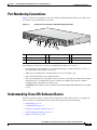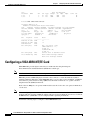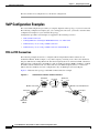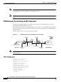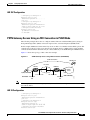
1
Cisco IAD2430 Series
Integrated Access Devices
Software Configuration Guide
THE SPECIFICATIONS AND INFORMATION REGARDING THE PRODUCTS IN THIS MANUAL ARE SUBJECT TO
CHANGE WITHOUT NOTICE. ALL STATEMENTS, INFORMATION, AND RECOMMENDATIONS IN THIS
MANUAL ARE BELIEVED TO BE ACCURATE BUT ARE PRESENTED WITHOUT WARRANTY OF ANY KIND,
EXPRESS OR IMPLIED. USERS MUST TAKE FULL RESPONSIBILITY FOR THEIR APPLICATION OF ANY
PRODUCTS.
Americas Headquarters
Cisco Systems, Inc.
170 West Tasman Drive
San Jose, CA 95134-1706
USA
http://www.cisco.com
Tel: 408 526-4000
800 553-NETS (6387)
Fax: 408 527-0883
Text Part Number: OL-4306-03
THE SOFTWARE LICENSE AND LIMITED WARRANTY FOR THE ACCOMPANYING PRODUCT ARE SET FORTH IN THE INFORMATION PACKET THAT
SHIPPED WITH THE PRODUCT AND ARE INCORPORATED HEREIN BY THIS REFERENCE. IF YOU ARE UNABLE TO LOCATE THE SOFTWARE LICENSE
OR LIMITED WARRANTY, CONTACT YOUR CISCO REPRESENTATIVE FOR A COPY.
The Cisco implementation of TCP header compression is an adaptation of a program developed by the University of California, Berkeley (UCB) as part of UCB’s public
domain version of the UNIX operating system. All rights reserved. Copyright © 1981, Regents of the University of California.
NOTWITHSTANDING ANY OTHER WARRANTY HEREIN, ALL DOCUMENT FILES AND SOFTWARE OF THESE SUPPLIERS ARE PROVIDED “AS IS” WITH
ALL FAULTS. CISCO AND THE ABOVE-NAMED SUPPLIERS DISCLAIM ALL WARRANTIES, EXPRESSED OR IMPLIED, INCLUDING, WITHOUT
LIMITATION, THOSE OF MERCHANTABILITY, FITNESS FOR A PARTICULAR PURPOSE AND NONINFRINGEMENT OR ARISING FROM A COURSE OF
DEALING, USAGE, OR TRADE PRACTICE.
IN NO EVENT SHALL CISCO OR ITS SUPPLIERS BE LIABLE FOR ANY INDIRECT, SPECIAL, CONSEQUENTIAL, OR INCIDENTAL DAMAGES, INCLUDING,
WITHOUT LIMITATION, LOST PROFITS OR LOSS OR DAMAGE TO DATA ARISING OUT OF THE USE OR INABILITY TO USE THIS MANUAL, EVEN IF CISCO
OR ITS SUPPLIERS HAVE BEEN ADVISED OF THE POSSIBILITY OF SUCH DAMAGES.
CCDE, CCENT, Cisco Eos, Cisco Lumin, Cisco Nexus, Cisco StadiumVision, Cisco TelePresence, Cisco WebEx, the Cisco logo, DCE, and Welcome to the Human Network
are trademarks; Changing the Way We Work, Live, Play, and Learn and Cisco Store are service marks; and Access Registrar, Aironet, AsyncOS, Bringing the Meeting To
You, Catalyst, CCDA, CCDP, CCIE, CCIP, CCNA, CCNP, CCSP, CCVP, Cisco, the Cisco Certified Internetwork Expert logo, Cisco IOS, Cisco Press, Cisco Systems,
Cisco Systems Capital, the Cisco Systems logo, Cisco Unity, Collaboration Without Limitation, EtherFast, EtherSwitch, Event Center, Fast Step, Follow Me Browsing,
FormShare, GigaDrive, HomeLink, Internet Quotient, IOS, iPhone, iQuick Study, IronPort, the IronPort logo, LightStream, Linksys, MediaTone, MeetingPlace,
MeetingPlace Chime Sound, MGX, Networkers, Networking Academy, Network Registrar, PCNow, PIX, PowerPanels, ProConnect, ScriptShare, SenderBase, SMARTnet,
Spectrum Expert, StackWise, The Fastest Way to Increase Your Internet Quotient, TransPath, WebEx, and the WebEx logo are registered trademarks of Cisco Systems, Inc.
and/or its affiliates in the United States and certain other countries.
All other trademarks mentioned in this document or website are the property of their respective owners. The use of the word partner does not imply a partnership relationship
between Cisco and any other company. (0809R)
Cisco IAD2430 Series Integrated Access Devices Software Configuration Guide
Copyright © 2003 - 2008 Cisco Systems, Inc. All rights reserved.
CONTENTS
Preface
vii
To Access Online User Documentation (PDF and HTML Formats)
CHAPTER
1
iii-viii
Understanding Interface Numbering and Cisco IOS Software Basics
1-1
Identifying Cisco IAD2430 Models 1-1
Cisco IAD2430-24FXS IAD 1-1
Cisco IAD2431-8FXS IAD 1-2
Cisco IAD2431-16FXS IAD 1-3
Cisco IAD2431-1T1E1 IAD 1-3
Cisco IAD2432-24FXS IAD 1-4
Cisco IAD2435-8FXS IAD 1-4
Port Numbering Conventions
1-5
Understanding Cisco IOS Software Basics
Getting Help 1-6
Command Modes 1-7
Undoing a Command or Feature 1-8
Saving Configuration Changes 1-8
Upgrading to a New Cisco IOS Release
1-5
1-8
Cisco IAD2430 Series Deployment Scenarios
Where to Go Next
CHAPTER
2
1-9
1-10
Using the setup Command Facility
2-1
Before Powering On Your Cisco IAD
The setup Command Facility
Configuring Global Parameters
2-1
2-2
2-2
Configuring Controller and Interface Parameters 2-5
Configuring Controller Parameters 2-5
Configuring Fast Ethernet and Serial Interface Parameters 2-5
Fast Ethernet WAN Interface Configuration 2-6
Serial Interface Configuration 2-7
T1/E1 Channelized Mode 2-9
Configuring a 1-Port, 4-Wire 56-kbps DSU/CSU Card 2-11
Choosing Circuit-Switched or Dedicated-Line Service 2-11
Switched Mode 2-12
Cisco IAD2430 Series Integrated Access Devices Software Configuration Guide
OL-4306-03
iii
Contents
Dedicated Mode
2-12
Completing the Configuration
CHAPTER
3
2-13
Configuring with the Command-Line Interface
3-1
Configuring the Hostname and Password 3-2
Verifying the Hostname and Password 3-3
Configuring Fast Ethernet Interfaces
Configuring Network Clock
3-4
3-5
Configuring T1/E1 Interfaces 3-7
Configuring Channel Groups on T1/E1 to Support Data 3-8
Configuring Channel Groups on T1/E1 to Support Data Under SHDSL Controller
Configuring Digital Voice on T1/E1 3-11
Configuring Switch Types for ISDN PRI Q.931 Support 3-12
Configuring DS0 Groups for CAS 3-14
Configuring TDM Cross-Connect 3-16
Configuring TDM to TDM 3-17
Configuring TDM to Analog Voice Port 3-18
Configuring TDM to Physical Serial Interface 3-18
Configuring a WIC-1DSU-T1/E1 Serial WAN Interface Card
3-20
Configuring a WIC-1T or WIC-2T Serial WAN Interface Card
3-24
Configuring a VIC2-2FXO or VIC2-4FXO Voice Interface Card
3-24
Configuring a VIC2-2FXS or VIC2-4FXS Voice Interface Card
3-26
Configuring ATM T1-WAN Ports 3-28
Verifying Your ATM Interface Configuration
3-10
3-31
Configuring 1-Port ADSL/SHDSL WAN Interface Card 3-32
Configuration Tasks 3-32
Configuring the ADSL/SHDSL Port on the ADSL and SHDSL WAN Interface Card
Verifying ATM Configuration 3-35
Configuring a VIC2-2BRI-NT/TE Card
Saving Configuration Changes
CHAPTER
4
Configuring Voice over IP
Prerequisites
3-32
3-36
3-38
4-1
4-1
Configuring the Voice Interface
4-2
VoIP Configuration Examples 4-4
FXS-to-FXS Connection 4-4
Configuration for IAD-1 4-5
Configuration for Router RLB-w
4-5
Cisco IAD2430 Series Integrated Access Devices Software Configuration Guide
iv
OL-4306-03
Contents
Configuration for Router R12-e 4-5
Configuration for IAD-2 4-6
Linking PBX Users with Digital E&M Trunk Lines over T1/E1 CAS 4-6
IAD SJ Configuration 4-7
IAD SLC Configuration 4-7
PSTN Gateway Access Using an FXO Connection 4-8
IAD SJ Configuration 4-8
IAD SLC Configuration 4-9
PSTN Gateway Access Using an FXO Connection in PLAR Mode 4-9
IAD SJ Configuration 4-9
IAD SLC Configuration 4-10
APPENDIX
A
Cisco IAD2430 Series Configuration Examples
Sample Configuration: Cisco IAD2435-8FXS
Sample Configuration: Cisco 2430-24FXS
A-1
A-1
A-3
Sample Configuration: Cisco 2431-1T1/E1 with WIC-2T
A-6
Sample Configuration: Cisco 2432-24FXS with VIC2-4FXO
and QoS A-8
APPENDIX
B
Formatting the Flash Memory
B-1
Formatting Procedures for Flash Memory B-1
Formatting Procedures B-1
Determining the File System on Flash Memory B-1
Formatting Flash Memory as a Class B Flash File System B-3
Formatting Flash Memory as a Class C File System B-4
File and Directory Operations B-5
Operations for Use with Class B Flash File System B-5
Operations for Use with Class C Flash File System B-7
File Operations for Class C Flash File System B-8
Directory Operations for Class C Flash File System B-10
APPENDIX
C
Using the ROM Monitor
C-1
Entering the ROM Monitor Mode
C-1
ROM Monitor Commands C-2
Command Descriptions C-3
Recovering Boot and System Images C-4
Using the xmodem Command C-4
Using the tftpdnld -r Command C-5
Cisco IAD2430 Series Integrated Access Devices Software Configuration Guide
OL-4306-03
v
Contents
Configuration Register C-6
Changing the Configuration Register Manually C-6
Changing the Configuration Register Using Prompts C-6
Console Download C-7
Command Description
Error Reporting C-8
Debug Commands
C-7
C-8
Exiting the ROM Monitor
C-9
INDEX
Cisco IAD2430 Series Integrated Access Devices Software Configuration Guide
vi
OL-4306-03
Preface
This preface describes the objectives, audience, organization, and conventions of this software
configuration guide, and where to get the latest version of this guide.
This preface presents the following major topics:
•
Objectives, page vii
•
Audience, page vii
•
Document Organization, page viii
•
Related and Referenced Documents, page viii
•
Obtaining Documentation and Submitting a Service Request, page ix
Objectives
After installing the router, use this guide to complete a basic router configuration using the setup
command facility. This guide also contains information on using the Cisco IOS software to perform
other configuration tasks, such as configuring a VoIP interface and other features.
This guide does not provide complete configuration instructions. See the Cisco IOS configuration guides
and command references for detailed configuration instructions.
Audience
This publication is designed for the person who will be responsible for configuring your router. This
guide is intended primarily for the following audiences:
•
Customers with technical networking background and experience
•
System administrators who are familiar with the fundamentals of router-based internetworking, but
who might not be familiar with Cisco IOS software
•
System administrators who are responsible for installing and configuring internetworking
equipment, and who are familiar with Cisco IOS software
Cisco IAD2430 Series Integrated Access Devices Software Configuration Guide
OL-4306-03
vii
Preface
Document Organization
The following table summarizes the major sections of this document.
Chapter
Title
Description
Chapter 1
Understanding Interface
Numbering and Cisco IOS
Software Basics
Provides an overview of the interface numbering
conventions for the Cisco IAD2430 series IADs. Also
provides a basic understanding of Cisco IOS software.
Chapter 2
Using the setup Command
Facility
Describes how to use the setup command facility to
configure your router.
Chapter 3
Configuring with the
Command-Line Interface
Describes how to use the Cisco IOS software
command-line interface (CLI) to configure basic router
functionality.
Chapter 4
Configuring Voice over IP
Describes how to configure voice network modules
with digital recEive and transMit (E&M) over T1/E1
CAS, foreign exchange office (FXO), and foreign
exchange station (FXS) interfaces for your router.
Appendix A
Cisco IAD2430 Series
Configuration Examples
Provides a variety of configuration examples:
•
Cisco IAD2431-8FXS
•
Cisco IAD2431-16FXS
•
Cisco IAD2430-24FXS
•
Cisco IAD 2431-1T1/E1 with WIC-2T
•
Cisco IAD2432-24FXS with VIC2-4FXO and QoS
•
Cisco IAD2435-8FXS
Appendix B
Formatting the Flash
Memory
Provides configuration information for the flash
memory.
Appendix C
Using the ROM Monitor
Describes how the ROM monitor works in the
Cisco IAD2430 series IAD.
Related and Referenced Documents
The documents described here are available online. To be sure of obtaining the latest information, you
should access the online documentation.
To print a document in its original page format, access the online document, and click the PDF icon.
You can also order printed copies of documents. See the “Obtaining Documentation and Submitting a
Service Request” section on page ix.
To Access Online User Documentation (PDF and HTML Formats)
From Cisco.com at http://www.cisco.com, choose Documentation, > Voice and Unified
Communications, > Voice Gateway, > Cisco IAD2400 Series Integrated Access Devices.
Cisco IAD2430 Series Integrated Access Devices Software Configuration Guide
viii
OL-4306-03
Preface
Obtaining Documentation and Submitting a Service Request
For information on obtaining documentation, submitting a service request, and gathering additional
information, see the monthly What’s New in Cisco Product Documentation, which also lists all new and
revised Cisco technical documentation, at:
http://www.cisco.com/en/US/docs/general/whatsnew/whatsnew.html
Subscribe to the What’s New in Cisco Product Documentation as a Really Simple Syndication (RSS) feed
and set content to be delivered directly to your desktop using a reader application. The RSS feeds are a free
service and Cisco currently supports RSS version 2.0.
Cisco IAD2430 Series Integrated Access Devices Software Configuration Guide
OL-4306-03
ix
Preface
Cisco IAD2430 Series Integrated Access Devices Software Configuration Guide
x
OL-4306-03
CH A P T E R
1
Understanding Interface Numbering and
Cisco IOS Software Basics
This chapter provides an overview of interface numbering in the Cisco IAD2430 series integrated access
devices (IADs). It also describes how to use the Cisco IOS software commands.
This chapter presents the following major topics:
•
Identifying Cisco IAD2430 Models, page 1-1
•
Port Numbering Conventions, page 1-5
•
Understanding Cisco IOS Software Basics, page 1-5
•
Upgrading to a New Cisco IOS Release, page 1-8
•
Cisco IAD2430 Series Deployment Scenarios, page 1-9
•
Where to Go Next, page 1-10
Identifying Cisco IAD2430 Models
Figure 1-1 shows the front panel of the Cisco IAD2430 series IAD. Figure 1-2 shows the front panel of
the Cisco IAD2435 IAD.
Cisco IAD2430-24FXS IAD
The Cisco IAD2430-24FXS provides 24 analog foreign exchange station (FXS) ports with two
10/100BASE-T ports. The chassis has the following interfaces:
•
RJ-21 analog voice interface
•
Two 10/100BASE-T ports
•
External flash memory
•
AC and DC power inputs
Cisco IAD2430 Series Integrated Access Devices Software Configuration Guide
OL-4306-03
1-1
Chapter 1
Understanding Interface Numbering and Cisco IOS Software Basics
Identifying Cisco IAD2430 Models
Figure 1-1
Cisco IAD2430-24FXS Chassis—Front Panel
2400
88839
CISCO IAD
Figure 1-2
0/0
FE
0/1
CD T1/E1
AL
2/0
2/1
2/2
2/3
FXS
2/4
2/5
2/6
2/7
Cisco IAD2
400
231872
OK
Cisco IAD2435-8FXS Chassis—Front Panel
SERIES
Cisco IAD2431-8FXS IAD
The Cisco IAD2431-8FXS provides eight analog FXS ports, two 10/100BASE-T ports, and one T1/E1
WAN port. The chassis has the following interfaces (see Figure 1-3):
•
RJ-21 analog voice interface
•
One T1/E1 port
•
One 10/100BASE-T port
•
One WIC/VIC slot
•
External flash memory
•
AC and DC power adapter
Figure 1-3
Cisco IAD2431-8FXS Chassis—Back Panel
-8FXS
88825
IAD2431
Cisco IAD2430 Series Integrated Access Devices Software Configuration Guide
1-2
OL-4306-03
Chapter 1
Understanding Interface Numbering and Cisco IOS Software Basics
Identifying Cisco IAD2430 Models
Cisco IAD2431-16FXS IAD
The Cisco IAD2431-16FXS provides 16 analog FXS ports with two 10/100BASE-T ports and one T1/E1
WAN ports. The chassis has the following interfaces (see Figure 1-4):
•
RJ-21 analog voice interface
•
One T1/E1 port
•
Two 10/100BASE-T ports
•
One WIC/VIC slot
•
External flash memory
•
AC and DC power inputs
Figure 1-4
Cisco IAD2431-16FXS Chassis—Back Panel
88826
IAD2431
-16FXS
Cisco IAD2431-1T1E1 IAD
The Cisco IAD2431-1T1E1 provides one T1/E1 connection to a PBX, one T1/E1 WAN port, and two
10/100BASE-T ports. The chassis has the following interfaces (see Figure 1-5):
•
One T1/E1 ports
•
Two 10/100BASE-T ports
•
One WIC/VIC slot
•
External flash memory
•
AC and DC power inputs
Figure 1-5
Cisco IAD2431-1T1E1 Chassis—Back Panel
-1T1E1
88827
IAD2431
Cisco IAD2430 Series Integrated Access Devices Software Configuration Guide
OL-4306-03
1-3
Chapter 1
Understanding Interface Numbering and Cisco IOS Software Basics
Identifying Cisco IAD2430 Models
Cisco IAD2432-24FXS IAD
The Cisco IAD2432-24FXS provides 24 analog FXS ports, two 10/100BASE-T ports, and two T1/E1
WAN ports. The chassis has the following interfaces (see Figure 1-6):
•
RJ-21 analog voice interface
•
Two T1/E1 ports
•
Two 10/100BASE-T ports
•
One WIC/VIC slot
•
External flash memory
•
AC and DC power inputs
Cisco IAD2432-24FXS Chassis—Back Panel
88824
Figure 1-6
Cisco IAD2435-8FXS IAD
The Cisco IAD2435-8FXS provides eight analog FXS ports, two Fast Ethernet ports, and one T1/E1
WAN port. The chassis has the following interfaces (see Figure 1-7):
•
RJ-21 analog voice interface
•
One T1/E1 port
•
Two Fast Ethernet ports
•
AC and DC power inputs
Figure 1-7
Cisco IAD2435-8FXS Chassis—Back Panel
FXS
IAD2435-
8FXS
WAN
et
CONSOLE
T1/E1
0/1
0/0
AUX
12V DC
SA
231873
FastEthern
Cisco IAD2430 Series Integrated Access Devices Software Configuration Guide
1-4
OL-4306-03
Chapter 1
Understanding Interface Numbering and Cisco IOS Software Basics
Port Numbering Conventions
Port Numbering Conventions
Figure 1-8 shows the port numbers of the Cisco IAD2432-24FXS IAD. The figure is provided to show
an example of the port numbering conventions.
Figure 1-8
Analog FXS User Interfaces with Metro Ethernet Interface
2
95001
1
5
3
4
6
7
8
9
1
RJ-21 connector
4
Flash memory port
7
Fast Ethernet port 0
2
T1/E1 port 0
5
WIC/VIC slot
8
AUX port
3
T1/E1 port 1
6
Fast Ethernet port 1
9
Console port
Port numbering conventions for all the Cisco IAD2430 series IADs are as follows:
•
Foreign Exchange Station (FXS) voice port numbering begins at 2/0 and extends to 2/7, 2/15, or
2/23, depending on the number of voice ports.
•
T1/E1 ports are numbered T1 or E1 1/0 and T1 or E1 1/1, from right to left.
•
The external flash memory port is numbered CF 0.
•
The slot for WAN interface cards (WICs) and voice interface cards (VICs) is numbered slot 0. WIC
and VIC interfaces are numbered by interface with this slot number and an interface number,
beginning with 0, and running from right to left.
•
10/100BASE-T Fast Ethernet ports are numbered Fast Ethernet 0/0 and Fast Ethernet 0/1, from right
to left.
Understanding Cisco IOS Software Basics
This section describes what you need to know about the Cisco IOS software before you configure the
router by using the command-line interface (CLI). This chapter includes the following:
•
Getting Help, page 1-6
•
Command Modes, page 1-7
•
Undoing a Command or Feature, page 1-8
•
Saving Configuration Changes, page 1-8
•
Where to Go Next, page 1-10
Cisco IAD2430 Series Integrated Access Devices Software Configuration Guide
OL-4306-03
1-5
Chapter 1
Understanding Interface Numbering and Cisco IOS Software Basics
Understanding Cisco IOS Software Basics
Understanding these concepts will save time as you begin to use the CLI. If you have never used
Cisco IOS software or if you need a refresher, take a few minutes to read this chapter before you proceed
to the next chapter.
Note
For a comprehensive view of Cisco IOS configuration fundamentals, see the Cisco IOS Configuration
Fundamentals Configuration Guide, Release 12.4 document.
If you are already familiar with Cisco IOS software, proceed to Chapter 2, “Using the setup Command
Facility.”
Getting Help
Use the question mark (?) and arrow keys to help you enter commands:
•
For a list of available commands, enter a question mark:
Router> ?
•
To complete a command, enter a few known characters followed by a question mark (with no space):
Router> s?
•
For a list of command variables, enter the command followed by a space and a question mark:
Router> show ?
•
To redisplay a command you previously entered, press the Up arrow key. You can continue to press
the Up arrow key for more commands.
Cisco IAD2430 Series Integrated Access Devices Software Configuration Guide
1-6
OL-4306-03
Chapter 1
Understanding Interface Numbering and Cisco IOS Software Basics
Understanding Cisco IOS Software Basics
Command Modes
The Cisco IOS user interface involves different modes. Each command mode permits you to configure
different components on your router. The commands available at any given time depend on which mode
you are currently in. Entering a question mark (?) at the prompt displays a list of commands available
for each command mode. Table 1-1 lists the most common command modes.
Table 1-1
Timesaver
Common Command Modes
Command Mode
Access Method
Router Prompt
Displayed
User EXEC
Log in.
Router>
Privileged EXEC
From user EXEC mode, Router#
enter the enable
command.
To exit to user EXEC
mode, use the disable,
exit, or logout
command.
Global configuration
From the privileged
EXEC mode, enter the
configure terminal
command.
To exit to privileged
EXEC mode, use the
exit or end command,
or press Ctrl-Z.
Interface configuration
From the global
Router (config-if)#
configuration mode,
enter the interface type
number command, such
as interface serial 0/0.
Router (config)#
Exit Method
Use the logout
command.
To exit to global
configuration mode, use
the exit command.
To exit directly to
privileged EXEC mode,
press Ctrl-Z.
Each command mode restricts you to a subset of commands. If you are having trouble entering a
command, check the prompt, and enter the question mark (?) for a list of available commands. You might
be in the wrong command mode or using the wrong syntax.
In the following example, notice how the prompt changes after each command to indicate a new
command mode:
Router> enable
Password: <enable password>
Router# configure terminal
Router(config)# interface serial 0/0
Router(config-if)# line 0
Router(config-line)# controller T1/E1 slot/port <---See second Note below
Router(config-controller)# exit
Router(config)# exit
Router#
%SYS-5-CONFIG_I: Configured from console by console
The last message is normal and does not indicate an error. Press Enter to get the Router# prompt.
Cisco IAD2430 Series Integrated Access Devices Software Configuration Guide
OL-4306-03
1-7
Chapter 1
Understanding Interface Numbering and Cisco IOS Software Basics
Upgrading to a New Cisco IOS Release
Note
You can press Ctrl-Z in any mode to immediately return to enable mode (Router#), instead of entering
exit, which returns you to the previous mode.
Note
In the Cisco IAD2430 series IADs, the controller port syntax is x/y, where
slot can be 0 (where 0 is the T1/E1 controller on a VWIC) or 1 (the onboard T1/E1), and
port can be 0 (the first port) or 1 (the second port).
See the “Port Numbering Conventions” section on page 1-5.
Undoing a Command or Feature
If you want to undo a command you entered or disable a feature, enter the keyword no before most
commands; for example, no ip routing.
Saving Configuration Changes
You need to enter the copy running-config startup-config command to save your configuration
changes to NVRAM, so the changes are not lost if there is a system reload or power outage. For example:
Router# copy running-config startup-config
Building configuration...
It might take a minute or two to save the configuration to NVRAM. After the configuration has been
saved, the following appears:
[OK]
Router#
Upgrading to a New Cisco IOS Release
To install or upgrade to a new Cisco IOS release, see Appendix B, “Formatting the Flash Memory.”
Note
To simplify network operations and management of Cisco IOS software migration, see the Basics of a
Successful Cisco IOS Software Migration document.
Cisco IAD2430 Series Integrated Access Devices Software Configuration Guide
1-8
OL-4306-03
Chapter 1
Understanding Interface Numbering and Cisco IOS Software Basics
Cisco IAD2430 Series Deployment Scenarios
Cisco IAD2430 Series Deployment Scenarios
Figure 1-9 through Figure 1-9 on page 1-9 show some typical deployment scenarios for Cisco IAD2430
series IADs.
Figure 1-9
Analog FXS User Interface with Metro Ethernet Interface
Ethernet
RJ-21
IAD
Distribution
panel
Figure 1-10
88997
Analog
telephones
Cisco IAD model number:
IAD2430-24FXS
T1/E1 WAN Interface with Analog FXS User Interface
Ethernet
T1
RJ-21
IAD
Analog
telephones
Cisco IAD model number:
IAD2431-8FXS
IAD2431-16FXS
IAD2432-24FXS
IAD2435-8FXS
Distribution
panel
88998
WAN
Cisco IAD2430 Series Integrated Access Devices Software Configuration Guide
OL-4306-03
1-9
Chapter 1
Understanding Interface Numbering and Cisco IOS Software Basics
Where to Go Next
Figure 1-11
T1/E1 WAN Interface with Analog FXS and FXO User Interfaces
Analog
telephones
Ethernet
WAN
T1
24 FXS
voice ports
Multiple FXS and FXO
IAD
PBX
Cisco IAD model number:
Cisco IAD2432-24FXS
with
Cisco VIC2-4FXO interface card
4 FXO
voice ports
PBX
Figure 1-12
88996
Distribution
panel
T1/E1 WAN Interface with T1 Interface to PBX User Interface
Ethernet
WAN
T1
T1
IAD
Cisco IAD model number:
IAD2431-1T1E1
88995
PBX
Where to Go Next
Now that you have learned some Cisco IOS software basics and seen some typical deployment scenarios,
you can begin to configure the router by using the command-line interface (CLI).
Remember that:
•
You can use the question mark (?) and arrow keys to help you enter commands.
•
Each command mode restricts you to a set of commands. If you have difficulty entering a command,
check the prompt and then enter the question mark (?) for a list of available commands. You might
be in the wrong command mode or be using the wrong syntax.
•
To disable a feature, generally enter the keyword no before the command; for example, no ip
routing.
•
You need to save your configuration changes to NVRAM so that the changes are not lost if there is
a system reload or power outage.
Go to Chapter 2, “Using the setup Command Facility,” to begin configuring the router.
Cisco IAD2430 Series Integrated Access Devices Software Configuration Guide
1-10
OL-4306-03
CH A P T E R
2
Using the setup Command Facility
This chapter describes how to use the setup command facility to configure your Cisco integrated access
device (IAD). The setup command facility prompts you to enter information needed to start a router
functioning quickly. The facility steps you through a basic configuration, including LAN and WAN
interfaces.
This chapter presents the following major topics:
•
Before Powering On Your Cisco IAD, page 2-1
•
The setup Command Facility, page 2-2
•
Configuring Global Parameters, page 2-2
•
Configuring Controller and Interface Parameters, page 2-5
•
Completing the Configuration, page 2-13
If you prefer to configure the router manually or if you wish to configure a module or interface that is
not included in the setup command facility, proceed to “Chapter 3, “Configuring with the
Command-Line Interface,” for step-by-step instructions.
If you prefer to configure the router by using AutoInstall, see the Using AutoInstall to Remotely
Configure Cisco Networking Devices document.
Before Powering On Your Cisco IAD
Before you power on your Cisco IAD and begin to use the setup command facility, follow these steps:
Step 1
Set up the hardware as described in the hardware installation documents for your Cisco IAD.
Step 2
Configure your PC terminal emulation program for 9600 baud, 8 data bits, no parity, and 1 stop bit.
Step 3
Determine which network protocols you are supporting.
Step 4
Determine the following for each network protocol:
•
Addressing plan
•
Which WAN protocols you will run on each interface (for example, Frame Relay [FR], High-Level
Data Link Control [HDLC], X.25, and so on)
Cisco IAD2430 Series Integrated Access Devices Software Configuration Guide
OL-4306-03
2-1
Chapter 2
Using the setup Command Facility
The setup Command Facility
The setup Command Facility
The setup command facility is displayed in your PC terminal emulation program window.
To create a basic configuration for your Cisco IAD, do the following:
Note
•
Complete the steps in the “Configuring Global Parameters” section on page 2-2.
•
Complete the steps in the “Configuring Controller and Interface Parameters” section on page 2-5
that apply to your Cisco IAD and network.
•
Complete the steps in the “Completing the Configuration” section on page 2-13.
If you make a mistake while using the setup command facility, you can exit and run the facility again.
Press Ctrl-C, and enter setup at the enable mode prompt (Router#).
Configuring Global Parameters
Step 1
Power on the Cisco IAD.
Note
To power on the Cisco IAD2435 IAD, plug in the external power supply.
Messages begin to appear in your terminal emulation program window.
Caution
Do not press any keys on the keyboard until the messages stop. Any keys pressed during this time are
interpreted as the first command typed when the messages stop, which might cause the Cisco IAD to
power off and start over. It takes a few minutes for the messages to stop.
The messages look similar to the following example.
Note
Much of the following example is largely for a Cisco IAD2431-1T1E1 IAD. The messages vary,
depending on the Cisco IOS software release, the interface modules in your Cisco IAD, and the
feature set you select. In addition, the word “Router” is the default prompt, and may appear
elsewhere; interpret this word as meaning “Cisco IAD.” The screen displays in this section are
for reference only and might not exactly match the messages on your console.
Also, although you see the interfaces of onboard and installed T1 controllers and installed serial
interface cards (such as the WIC-2T), you do not see the interfaces of installed voice interface
cards.
Note
The Cisco IAD2435 router is a fixed-configuration router and does not support interface cards.
System Bootstrap, Version 12.4(20080418:075150)
[BLD-iad.IAD_APRIL18_POST_SYNC_BUILD_UBLDIT-for_gopasaha 102], DEVELOPMENT SOFTWARE
Copyright (c) 1994-2008 by cisco Systems, Inc.
C2431 platform with 262144 Kbytes of main memory
Cisco IAD2430 Series Integrated Access Devices Software Configuration Guide
2-2
OL-4306-03
Chapter 2
Using the setup Command Facility
Configuring Global Parameters
Upgrade ROMMON initialized
program load complete, entry point: 0x80020000, size: 0x18d54b8
Self decompressing the image :
##########################################################################################
##########################################################################################
################################# [OK]
Restricted Rights Legend
Use, duplication, or disclosure by the Government is
subject to restrictions as set forth in subparagraph
(c) of the Commercial Computer Software - Restricted
Rights clause at FAR sec. 52.227-19 and subparagraph
(c) (1) (ii) of the Rights in Technical Data and Computer
Software clause at DFARS sec. 252.227-7013.
cisco Systems, Inc.
170 West Tasman Drive
San Jose, California 95134-1706
Cisco IOS Software, C2435 Software (C2435-ADVIPSERVICESK9-M), Version
12.4(IAD_APRIL18_POST_SYNC_BUILD.2008-04-17) UBUILDIT Image, CISCO DEVELOPMENT TEST
VERSION
Copyright (c) 1986-2008 by Cisco Systems, Inc.
Compiled Fri 18-Apr-08 01:58 by gopasaha
This product contains cryptographic features and is subject to United
States and local country laws governing import, export, transfer and
use. Delivery of Cisco cryptographic products does not imply
third-party authority to import, export, distribute or use encryption.
Importers, exporters, distributors and users are responsible for
compliance with U.S. and local country laws. By using this product you
agree to comply with applicable laws and regulations. If you are unable
to comply with U.S. and local laws, return this product immediately.
A summary of U.S. laws governing Cisco cryptographic products may be found at:
http://www.cisco.com/wwl/export/crypto/tool/stqrg.html
If you require further assistance please contact us by sending email to
[email protected].
Cisco IAD2435 (MPC8323E) processor (revision 0x100) with 249856K/12288K bytes of memory.
Processor board ID FOC11375MBF
MPC8300 CPU Rev: Part Number 0x8062, Revision ID 0x11
2 FastEthernet interfaces
8 Voice FXS interfaces
256K bytes of non-volatile configuration memory.
126000K bytes of ATA Flash (Read/Write)
--- System Configuration Dialog --Would you like to enter the initial configuration dialog? [yes/no]: y
At any point you may enter a question mark '?' for help.
Use ctrl-c to abort configuration dialog at any prompt.
Default settings are in square brackets '[]'.
Cisco IAD2430 Series Integrated Access Devices Software Configuration Guide
OL-4306-03
2-3
Chapter 2
Using the setup Command Facility
Configuring Global Parameters
Step 2
When the following message appears, enter yes to begin the initial configuration dialog:
Would you like to enter the initial configuration dialog? [yes/no]:
Note
If you answer no to this message, you are prompted to terminate AutoInstall. AutoInstall is a
procedure that configures a new Cisco IAD based on the configuration of an existing
Cisco IAD.
If you terminate AutoInstall, you enter the Cisco IOS software CLI.
Note
Step 3
The number of interfaces shown depends on the Cisco IAD2430 series model.
When the following message appears, press Enter to see the current interface summary:
First, would you like to see the current interface summary? [yes]:
Any interface listed with OK? value “NO” does not have a valid configuration
Interface
FastEthernet0/0
FastEthernet0/1
Step 4
IP-Address
unassigned
unassigned
OK? Method Status
NO unset up
NO unset up
Protocol
up
down
Enter a hostname for the Cisco IAD:
Configuring global parameters:
Enter hostname [Router]: IAD2435
The enable secret is a password used to protect access to privileged EXEC and
configuration modes. This password, after entered, becomes encrypted in the configuration.
Step 5
Enter an enable secret password. This password is encrypted (more secure) and cannot be seen when
viewing the configuration:
Enter enable secret: xxxx
The enable password is used when you do not specify an enable secret password, with some
older software versions, and some boot images.
Step 6
Enter an enable password that is different from the enable secret password. This password is not
encrypted (less secure) and can be seen when viewing the configuration:
Enter enable password: guessme
The virtual terminal password is used to protect access to the router over a network
interface.
Step 7
Enter the virtual terminal password, which prevents unauthenticated access to the router through ports
other than the console port:
Enter virtual terminal password: guessagain
Step 8
Respond to the following prompts as appropriate for your network:
Configure SNMP Network Management? [yes]: n
Configure bridging? [no]:
Configure IP? [yes]:
Configure RIP routing? [yes]: n
Configure CLNS? [no]:
Cisco IAD2430 Series Integrated Access Devices Software Configuration Guide
2-4
OL-4306-03
Chapter 2
Using the setup Command Facility
Configuring Controller and Interface Parameters
Note
If you answer no to Interior Gateway Routing Protocol (IGRP), you are prompted to configure
Routing Information Protocol (RIP).
Configuring Controller and Interface Parameters
From this point on in the setup process, the prompts you see vary, depending on the interface cards
installed in your Cisco IAD.
Note
The Cisco IAD2435 router is a fixed-configuration router and does not support interface cards.
The following sections provide examples of the setup steps for cards. See the sections appropriate to
your Cisco IAD.
Configuration examples include the following:
•
Configuring Controller Parameters, page 2-5
•
Configuring Fast Ethernet and Serial Interface Parameters, page 2-5
•
Configuring a 1-Port, 4-Wire 56-kbps DSU/CSU Card, page 2-11
When you complete the setup steps for your interface modules, go to the “Completing the
Configuration” section on page 2-13 for directions on saving your configuration.
Configuring Controller Parameters
Controllers can be either built in or on an interface module.
Configuring controller parameters. Controllers are hardware on the router
that you connect directly to a T1 or E1 line from your Telco. Configure
controllers for such purposes as Primary Rate ISDN(PRI) and/or
Channelized T1 or Channelized E1.
Note: J1 controllers are not configurable in setup mode.
Configuring controller T1 1/0 in pri or channelized mode
Do you want to configure this controller ? [yes]: no
Configuring Fast Ethernet and Serial Interface Parameters
This section provides examples for the following:
•
Fast Ethernet WAN Interface Configuration
•
Serial Interface Configuration
Cisco IAD2430 Series Integrated Access Devices Software Configuration Guide
OL-4306-03
2-5
Chapter 2
Using the setup Command Facility
Configuring Controller and Interface Parameters
Fast Ethernet WAN Interface Configuration
This section provides sample steps and configuration for the Fast Ethernet WAN interface.
SUMMARY STEPS
1.
enable
2.
configure terminal
3.
interface type/number
4.
ip address ip address/subnet mask
5.
no shutdown
6.
end
DETAILED STEPS
Step 1
Command or Action
Purpose
enable
Enters privileged EXEC mode.
Example:
Router# enable
Step 2
configure terminal
Enters global configuration mode.
Example:
Router# configure terminal
Step 3
interface type/number
Enters the configuration mode for a Fast Ethernet WAN
interface on the router.
Example:
Router(config)# interface fastethernet 2
Router(config-if)#
Step 4
ip address ip address/subnet mask
Sets the IP address and subnet mask for the specified Fast
Ethernet interface.
Example:
Router(config-if)# ip address 192.168.12.2
255.255.255.0
Router(config-if)#
Cisco IAD2430 Series Integrated Access Devices Software Configuration Guide
2-6
OL-4306-03
Chapter 2
Using the setup Command Facility
Configuring Controller and Interface Parameters
Step 5
Command or Action
Purpose
no shutdown
Enables the Fast Ethernet interface, changing its state
from administratively down to administratively up.
Example:
Router(config-if)# no shutdown
Router(config-if)#
Step 6
Exits configuration mode for the Fast Ethernet interface
and returns to global configuration mode.
exit
Example:
Router(config-if)# exit
Router(config)#
Serial Interface Configuration
This section provides a sample configuration for the 1- or 2-port serial interface on a WAN interface
card (WIC) when it is installed. Enter the values appropriate for your interface card and network.
Note
The Cisco IAD2435 router is a fixed-configuration router and does not support interface cards.
The messages you see may vary.
Do you want to configure Serial0/0 interface? [yes]:
Some encapsulations supported are
ppp/hdlc/frame-relay/lapb/atm-dxi/smds/x25
Choose encapsulation type
[ppp]:
The “Frame Relay Encapsulation” section on page 2-8 through “SMDS Encapsulation” section on
page 2-9 show the prompts for each encapsulation type. For PPP and High-Level Data Link Control
(HDLC) encapsulation, no further configuration is needed.
No serial cable seen.
Choose mode from (dce/dte) [dte]:
If no cable is plugged into your interface card, you must indicate whether the interface is to be used as
DTE or DCE. If a cable is present, the setup command facility determines the DTE/DCE status. If the
serial cable is DCE, you see the following prompt:
Serial interface needs clock rate to be set in dce mode.
The following clock rates are supported on the serial interface.
0
1200, 2400, 4800, 9600, 19200, 38400
56000, 64000, 72000, 125000, 148000, 500000
800000, 1000000, 1300000, 2000000, 4000000, 8000000
Choose clock rate from above: [2000000]:
Configure IP on this interface? [yes]:
IP address for this interface: 2.0.0.1
Subnet mask for this interface [255.0.0.0] : 255.255.255.0
Class A network is 9.0.0.0, 24 subnet bits; mask is /24
Cisco IAD2430 Series Integrated Access Devices Software Configuration Guide
OL-4306-03
2-7
Chapter 2
Using the setup Command Facility
Configuring Controller and Interface Parameters
Sample configurations for the following encapsulation types are provided in this section:
•
Frame Relay Encapsulation
•
LAPB Encapsulation
•
X.25 Encapsulation
•
SMDS Encapsulation
Frame Relay Encapsulation
The following is an example of a typical Frame Relay encapsulation configuration:
The following lmi-types are available to be set,
when connected to a frame relay switch
[0] none
[1] ansi
[2] cisco
[3] q933a
Enter lmi-type [2]:
Note
The setup command facility prompts for the data-link connection identifier (DLCI) number only if you
specify none for the Local Management Interface (LMI) type. If you accept the default or specify
another LMI type, the DLCI number is provided by the specified protocol.
Enter the DLCI number for this interface [16]:
Do you want to map a remote machine’s IP address to dlci? [yes]:
IP address for the remote interface: 2.0.0.2
Do you want to map a remote machine’s IPX address to dlci? [yes]:
IPX address for the remote interface: 40.1234.5678
Serial interface needs clock rate to be set in dce mode.
The following clock rates are supported on the serial interface.
0
1200, 2400, 4800, 9600, 19200, 38400
56000, 64000, 72000, 125000, 148000, 500000
800000, 1000000, 1300000, 2000000, 4000000, 8000000
choose speed from above: [2000000]: 1200
Configure IP on this interface? [yes]:
IP address for this interface: 2.0.0.1
Subnet mask for this interface [255.0.0.0]:
Class A network is 2.0.0.0, 8 subnet bits; mask is /8
LAPB Encapsulation
The following is an example of a typical LAPB configuration:
lapb circuit can be either in dce/dte mode.
Choose either from (dce/dte) [dte]:
Cisco IAD2430 Series Integrated Access Devices Software Configuration Guide
2-8
OL-4306-03
Chapter 2
Using the setup Command Facility
Configuring Controller and Interface Parameters
X.25 Encapsulation
The following is an example of a typical X.25 encapsulation configuration:
x25 circuit can be either in dce/dte mode.
Choose from either dce/dte [dte]:
Enter local x25 address: 1234
We will need to map the remote x.25 station’s x25 address
to the remote stations IP/IPX address
Enter remote x25 address: 4321
Do you want to map the remote machine’s x25 address to IP address? [yes]:
IP address for the remote interface: 2.0.0.2
Do you want to map the remote machine’s x25 address to IPX address? [yes]:
IPX address for the remote interface: 40.1234.5678
Enter
Enter
Enter
Enter
Enter
lowest 2-way channel [1]:
highest 2-way channel [64]:
frame window (K) [7]:
Packet window (W) [2]:
Packet size (must be powers of 2) [128]:
SMDS Encapsulation
The following is an example of a typical SMDS configuration:
Enter smds address for the local interface: c141.5556.1415
We will need to map the remote smds station’s address
to the remote stations IP/IPX address
Enter smds address for the remote interface: c141.5556.1414
Do you want to map the remote machine’s smds address to IP address? [yes]:
IP address for the remote interface: 2.0.0.2
Do you want to map the remote machine’s smds address to IPX address? [yes]:
IPX address for the remote interface: 40.1234.5678
Serial Cisco IOS Commands Generated
The following is an example of the Cisco IOS commands generated by a typical serial configuration:
interface Serial0/0
encapsulation ppp
clock rate 2000000
ip address 2.0.0.1 255.0.0.0
T1/E1 Channelized Mode
The following is an example of a T1 channelized mode configuration using the setup command facility:
The following framing types are available:
esf | sf
Enter the framing type [esf]:
The following linecode types are available:
ami | b8zs
Enter the line code type [b8zs]:
Cisco IAD2430 Series Integrated Access Devices Software Configuration Guide
OL-4306-03
2-9
Chapter 2
Using the setup Command Facility
Configuring Controller and Interface Parameters
T1 is capable of being configured for channel 1-24
Enter number of time slots [24]: 3
Configure more channel groups? [no]: y
Enter number of time slots [21]: 3
Configure more channel groups? [no]: y
Enter number of time slots [18]: 3
Configure more channel groups? [no]: y
Enter number of time slots [15]:
Configure more channel groups? [no]:
The “PPP Encapsulation” section on page 2-10 through the “SMDS Encapsulation” section on page 2-11
show the prompts and provide examples for configuring each encapsulation type. No further
configuration is needed for HDLC encapsulation.
Sample configuration for the following encapsulation types are provided in this section:
•
PPP Encapsulation
•
Frame Relay Encapsulation
•
LAPB Encapsulation
•
SMDS Encapsulation
PPP Encapsulation
The following is an example of a typical PPP encapsulation configuration:
Would you like to enable multilink PPP [yes]:
Enter a remote hostname for PPP authentication [Router]:
Enter a password for PPP authentication:
Note
The password, which is used by the Challenge Handshake Authentication Protocol (CHAP)
authentication process, is case sensitive and must exactly match the remote router’s password.
Frame Relay Encapsulation
The following is an example of a typical Frame Relay encapsulation configuration:
The following lmi-types are available to be set,
when connected to a frame relay switch
[0] none
[1] ansi
[2] cisco
[3] q933a
Enter lmi-type [2]:
Note
The setup command facility prompts for the data-link connection identifier (DLCI) number only if you
specify none for the Local Management Interface (LMI) type. If you accept the default or specify
another LMI type, the DLCI number is provided by the specified protocol.
Enter the DLCI number for this interface [16]:
Do you want to map a remote machine’s IP address to dlci? [yes]:
IP address for the remote interface: 2.0.0.2
Do you want to map a remote machine’s IPX address to dlci? [yes]:
IPX address for the remote interface: 40.1234.5678
Serial interface needs clock rate to be set in dce mode.
Cisco IAD2430 Series Integrated Access Devices Software Configuration Guide
2-10
OL-4306-03
Chapter 2
Using the setup Command Facility
Configuring Controller and Interface Parameters
The following clock rates are supported on the serial interface.
0
1200, 2400, 4800, 9600, 19200, 38400
56000, 64000, 72000, 125000, 148000, 500000
800000, 1000000, 1300000, 2000000, 4000000, 8000000
choose speed from above: [2000000]: 1200
Configure IP on this interface? [yes]:
IP address for this interface: 2.0.0.1
Subnet mask for this interface [255.0.0.0]:
Class A network is 2.0.0.0, 8 subnet bits; mask is /8
LAPB Encapsulation
The following is an example of a typical LAPB encapsulation configuration:
lapb circuit can be either in dce/dte mode
Choose either from (dce/dte) [dte]:
SMDS Encapsulation
The following is an example of a typical SMDS encapsulation configuration:
Enter smds address for the local interface: c141.5556.1415
We will need to map the remote smds station's address to the remote stations IP address
Enter smds address for the remote interface: c141.5556.1414
Do you want to map the remote machine's smds address to IP address? [yes]:
IP address for the remote interface: 2.0.0.1
Do you want to map the remote machine's smds address to IP address? [yes]:
IPX address for the remote interface: 40.0060.34c6.90ed
Configuring a 1-Port, 4-Wire 56-kbps DSU/CSU Card
This section describes using the setup command facility to configure a 1-port, 4-wire 56-kbps DSU/CSU
WAN interface card (for example, the WIC-1DSU-T1/E1).
Note
The Cisco IAD2435 router is a fixed-configuration router and does not support interface cards.
Choosing Circuit-Switched or Dedicated-Line Service
The switched-56 WAN interface card is configured for dedicated, or leased-line, service by default, but
it can also be configured for circuit-switched service. Depending on the type of data transmissions you
typically use, you can configure the switched-56 WAN interface card for circuit-switched or
dedicated-line service.
Generally, circuit-switched service is ideal for short-duration data transmissions or as an alternative
route if a dedicated line fails. For example, circuit-switched service is ideal for sending electronic mail
messages or doing such tasks as updating inventory and ordering records from one network database to
another at the end of each day.
Dedicated service is ideal for heavy network traffic. Dedicated service is ideal if you need a constant
network connection or you need connection for more than eight hours per day.
Cisco IAD2430 Series Integrated Access Devices Software Configuration Guide
OL-4306-03
2-11
Chapter 2
Using the setup Command Facility
Configuring Controller and Interface Parameters
Switched Mode
The following is an example of a 1-port, 4-wire 56-kbps DSU/CSU switched-mode configuration using
the setup command facility:
Do you want to configure Serial0/0 interface? [yes]:
Some encapsulations supported are
ppp/hdlc/frame-relay/lapb/atm-dxi/smds/x25
Choose encapsulation type
[ppp]:
Switched 56k interface may either be in switched/Dedicated mode
Choose from either (switched/dedicated) [switched]:
The following switched carrier types are to be set when in switched mode
(at&t, sprint or other)
Choose carrier (at&t/sprint/other) [other]:
Do you want to map the remote machine's ip address in dialer map? [yes]:
IP address for the remote interface : 1.0.0.2
Note
The setup command facility asks for only one telephone number for both IP and IPX (if IPX is enabled).
Please enter the phone number to call : 1234567890
Configure IP on this interface? [yes]:
IP address for this interface: 1.0.0.1
Subnet mask for this interface [255.0.0.0] :
Class A network is 1.0.0.0, 8 subnet bits; mask is /8
Dedicated Mode
The following is an example of a 1-port, 4-wire 56-kbps DSU/CSU dedicated-mode configuration using
the setup command facility:
Do you want to configure Serial0/0 interface? [yes]:
Some encapsulations supported are
ppp/hdlc/frame-relay/lapb/atm-dxi/smds/x25
Choose encapsulation type
[ppp]:
Switched 56k interface may either be in switched/Dedicated mode
Choose from either (switched/dedicated) [switched]: dedi
When in dds mode, the clock for sw56 module can either from line/internal.
Choose clock from (line/internal) [line]:
Note
If internal is selected, speed cannot be set to “auto.” Autosensing is allowed only when the clock source
is line.
When in dds mode, the clock for sw56 module can either be from line/internal.
Choose clock from (line/internal) [line]: internal
Warning: internal can be choose only when connected back to back.
Serial interface needs clock rate to be set in dce mode.
The following clock rates are supported on the serial interface.
auto, 2.4, 4.8, 9.6, 19.2, 38.4
Cisco IAD2430 Series Integrated Access Devices Software Configuration Guide
2-12
OL-4306-03
Chapter 2
Using the setup Command Facility
Completing the Configuration
56, 64
choose clock rate from above [56]:
Configure IP on this interface? [yes]:
IP address for this interface: 1.0.0.1
Subnet mask for this interface [255.0.0.0] :
Class A network is 1.0.0.0, 8 subnet bits; mask is /8
Completing the Configuration
When you have all the information that the setup command facility has prompted you for, the
configuration appears.
Note
For sample configurations, see Appendix A, “Cisco IAD2430 Series Configuration Examples.”
To complete your configuration, follow these steps:
Step 1
A setup command facility prompt asks if you want to save this configuration, with the following options:
[0] Go to the IOS command prompt without saving this config.
[1] Return back to the setup without saving this config.
[2] Save this configuration to nvram and exit.
If you answer 0, the configuration information you entered is not saved, and you return to the Cisco IAD
enable prompt (Router#). Enter setup to return to the System Configuration Dialog.
If you answer 1, you return to setup without saving the configuration.
If you answer 2, the configuration is saved and you are returned to the user EXEC prompt (Router>).
Step 2
When the messages stop appearing on your screen, press Enter to get the Router> prompt.
Step 3
The Router> prompt indicates that you are now at the command-line interface (CLI) and you have just
completed a basic Cisco IAD configuration. However, this is not a complete configuration. At this point
you have two choices:
•
Run the setup command facility again and create another configuration. Enter the following:
Router> enable
Password: password
Router# setup
•
Modify the existing configuration or configure additional features with the CLI as described in
Chapter 3, “Configuring with the Command-Line Interface.”
Cisco IAD2430 Series Integrated Access Devices Software Configuration Guide
OL-4306-03
2-13
Chapter 2
Using the setup Command Facility
Completing the Configuration
Cisco IAD2430 Series Integrated Access Devices Software Configuration Guide
2-14
OL-4306-03
CH A P T E R
3
Configuring with the Command-Line Interface
This chapter describes how to use the Cisco IOS software command-line interface (CLI) to configure
basic Cisco integrated access device (IAD) functionality.
This chapter presents the following major topics:
•
Configuring the Hostname and Password, page 3-2
•
Configuring Fast Ethernet Interfaces, page 3-4
•
Configuring Network Clock, page 3-5
•
Configuring T1/E1 Interfaces, page 3-7
•
Configuring a WIC-1DSU-T1/E1 Serial WAN Interface Card, page 3-20
•
Configuring a WIC-1T or WIC-2T Serial WAN Interface Card, page 3-24
•
Configuring a VIC2-2FXO or VIC2-4FXO Voice Interface Card, page 3-24
•
Configuring a VIC2-2FXS or VIC2-4FXS Voice Interface Card, page 3-26
•
Configuring ATM T1-WAN Ports, page 3-28
•
Configuring 1-Port ADSL/SHDSL WAN Interface Card, page 3-32
•
Configuring a VIC2-2BRI-NT/TE Card, page 3-36
•
Saving Configuration Changes, page 3-38
Follow the procedures in this chapter to configure the Cisco IAD manually or, if you wish, to change the
configuration after you have run the setup command facility (see the “The setup Command Facility”
section on page 2-2).
This chapter does not describe every configuration possible—only a small portion of the most commonly
used configuration procedures. For advanced configuration topics, see the Cisco IOS configuration
guide and command reference publications. See the “Obtaining Documentation and Submitting a
Service Request” section on page -ix.
Note
If you skipped Chapter 2, “Using the setup Command Facility,” and you have never configured a
Cisco IAD, return to Chapter 2, “Using the setup Command Facility,” and read it now. The chapter
contains important information that you need for configuring your Cisco IAD.
Note
The Cisco IAD2435 router is a fixed-configuration router and does not support interface cards.
Cisco IAD2430 Series Integrated Access Devices Software Configuration Guide
OL-4306-03
3-1
Chapter 3
Configuring with the Command-Line Interface
Configuring the Hostname and Password
Configuring the Hostname and Password
One of the first configuration tasks is to configure the hostname and set an encrypted password.
Configuring a hostname allows you to distinguish multiple Cisco IADs and routers from each other.
Setting an encrypted password allows you to prevent unauthorized configuration changes.
Note
A hostname can be specified only when the router has a DNS server available for hostname resolution.
To configure the hostname and password, perform the following steps.
SUMMARY STEPS
1.
enable
2.
configure terminal
3.
hostname
4.
enable secret password
5.
line-console
6.
exec-timeout
7.
exit
8.
end
DETAILED STEPS
Step 1
Command or Action
Purpose
enable
Enters privileged EXEC mode.
Example:
Router# enable
Step 2
configure terminal
Enters global configuration mode.
Example:
Router# configure terminal
Step 3
hostname
Changes the name of the Cisco IAD to a meaningful
name.
Example:
Router(config)# hostname IAD2430
Step 4
enable secret password
Example:
Router(config)# enable secret guessme
Enters an enable secret password. This password
provides access to privileged EXEC mode. When you
press Enter at the user EXEC prompt
(Router>), you must enter the enable secret password to
gain access to configuration mode. Substitute your
enable secret password for guessme.
Cisco IAD2430 Series Integrated Access Devices Software Configuration Guide
3-2
OL-4306-03
Chapter 3
Configuring with the Command-Line Interface
Configuring the Hostname and Password
Step 5
Command or Action
Purpose
line console
Enters line configuration mode to configure the console
port. When you enter line configuration mode, the
prompt changes to Router(config-line)#.
Example:
Router(config)# line console 0
Step 6
exec-timeout
Example:
Router(config-line)# exec-timeout 0 0
If no input is detected during the interval, the EXEC
facility resumes the current connection. If no
connections exist, the EXEC facility returns the terminal
to the idle state and disconnects the incoming session.
Note
Step 7
To specify no timeout, enter the
exec-timeout 0 0 command.
Exits to global configuration mode.
exit
Example:
Router(config-line)# exit
Step 8
Returns you to privileged EXEC mode.
end
Example:
Router(config-if)# end
Verifying the Hostname and Password
To verify that you configured the correct hostname and password, follow these steps:
Step 1
Enter the show config command:
Router(config)# show config
Using 1888 out of 126968 bytes
!
version XX.X
.
.
.
!
hostname IAD2430
!
enable secret 5 $1$60L4$X2JYOwoDc0.kqa1loO/w8/
.
.
.
Check the hostname and encrypted password displayed near the top of the command output.
Step 2
Exit global configuration mode and attempt to reenter it, using the new enable password:
Router# exit
.
.
.
Router con0 is now available
Press RETURN to get started.
Router> enable
Cisco IAD2430 Series Integrated Access Devices Software Configuration Guide
OL-4306-03
3-3
Chapter 3
Configuring with the Command-Line Interface
Configuring Fast Ethernet Interfaces
Password: guessme
Router#
Tip
If you are having trouble, ensure the following:
•
Caps Lock is off.
•
You entered the correct passwords. Passwords are case sensitive.
Configuring Fast Ethernet Interfaces
To configure a Fast Ethernet interface, use the configuration software provided with your Cisco IAD or
network module, if any. Otherwise, for greatest power and flexibility, use configuration mode (manual
configuration).
Note
Before you begin, disconnect all WAN cables from the Cisco IAD to prevent it from running the
AutoInstall process. Whenever you power on the Cisco IAD, if there is a WAN connection on both ends
and the Cisco IAD does not have a valid configuration file stored in NVRAM (for instance, when you
add a new interface), the Cisco IAD tries to run AutoInstall. It can take several minutes for the Cisco
IAD to determine that AutoInstall is not connected to a remote TCP/IP host.
This section describes basic Fast Ethernet interface configuration, including enabling the interface and
specifying IP routing. Depending on your own requirements and the protocols you plan to route, you
might also need to enter other configuration commands.
Before you begin configuring the interfaces, make sure to do the following:
•
Connect a console to the Cisco IAD.
•
Power on the Cisco IAD.
To configure Fast Ethernet interfaces, perform the following steps.
SUMMARY STEPS
1.
enable
2.
configure terminal
3.
ip routing
4.
interface type number
5.
ip address ip address subnet mask
6.
exit
7.
Ctrl-z
Cisco IAD2430 Series Integrated Access Devices Software Configuration Guide
3-4
OL-4306-03
Chapter 3
Configuring with the Command-Line Interface
Configuring Network Clock
DETAILED STEPS
Step 1
Command or Action
Purpose
enable
Enters privileged EXEC mode.
Example:
Router# enable
Step 2
Enters global configuration mode.
configure terminal
Example:
Router# configure terminal
Step 3
Enables routing protocols as required for your global
configuration. This example uses IP routing.
ip routing
Example:
Router(config)# ip routing
Step 4
Enters interface configuration mode. You have entered
interface configuration mode when the prompt changes
to Router(config-if)#.
interface type number
Example:
Router(config)# interface fastethernet 0/0
Step 5
Assigns an IP address and subnet mask to the interface.
ip address ip address subnet mask
Example:
Router(config-if)# ip address 172.16.74.3
255.255.255.0
Step 6
exit
Exits to global configuration mode.
Example:
Repeat Step 4 through Step 6 if your Cisco IAD has more
than one interface to configure.
Router(config-if)# exit
Step 7
Returns to enable mode when you finish configuring the
interfaces.
Ctrl-z
Example:
Router# Ctrl-z
Configuring Network Clock
At initialization, all controllers on the Cisco IAD2430 IAD, including onboard T1/E1 or VWIC T1/E1,
participate in the system clock domain. The default network clock algorithm selects one of the
controllers as a default network clock. The default network clock algorithm provides a best estimate of
the clocking system. This is mainly for voice applications to be configured easily after power up.
Cisco recommends that when you power up the system, make sure that network clocks are configured
properly for the applications to work, with consideration for the specific network system requirements.
To view the current primary clock, use the show network-clocks or show run command. Note that the
show network-clocks and show run commands do not display the default network clock, which is
selected by the default network clock algorithm.
Cisco IAD2430 Series Integrated Access Devices Software Configuration Guide
OL-4306-03
3-5
Chapter 3
Configuring with the Command-Line Interface
Configuring Network Clock
To have the T1/E1 controller participate as a clock source for the Cisco IAD system clock domain and
to make sure it is available as a candidate for a clock selection algorithm, use the following CLI
configuration. If you have data applications that do not require clock participation, use the no form of
the commands.
To configure the network clock, perform the following steps.
SUMMARY STEPS
1.
enable
2.
configure terminal
3.
network-clock-participate slot/port
4.
controller {t1 | e1 | j1} slot/port
5.
network-clock-participate slot/port
6.
network-clock-select priority bri|atm|t1|e1 slot/port
7.
network-clock-select priority serial slot/port
8.
exit
9.
Ctrl-z
DETAILED STEPS
Step 1
Command or Action
Purpose
enable
Enters privileged EXEC mode.
Example:
Router# enable
Step 2
configure terminal
Enters global configuration mode.
Example:
Router# configure terminal
Step 3
network-clock-participate slot/port
Enters the controller into the system clock domain.
Note
Example:
Router(config)# network-clock-participate WIC 0
Step 4
controller t1 slot/port
The IAD2435 IAD is configured with
network-clock-participate by default. You
cannot remove or configure this default
configuration.
Enters the first part of the VWIC controller at slot 0 into
the system clock domain.
Example:
Router(config)# controller t1 0/2
Step 5
network-clock-participate slot/port
Enters both parts of the VWIC controller at slot 0 into the
system clock domain.
Example:
Router(config-controller)# controller t1 0/2
Router(config-controller)#
network-clock-participate wic 0
Cisco IAD2430 Series Integrated Access Devices Software Configuration Guide
3-6
OL-4306-03
Chapter 3
Configuring with the Command-Line Interface
Configuring T1/E1 Interfaces
Step 6
Command or Action
Purpose
network-clock-select priority {bri|atm|t1|e1}
slot/port
Selects the controller as a candidate for the clock
selection algorithm according to the priority entered. Use
either slots 1/0 or 0/0.
Example:
Router(config)# network-clock-select 1 T1 1/0
Step 7
network-clock-select priority serial slot/port
Example:
Router(config)# network-clock-select 1 Serial 0/0
Step 8
In case of a serial interface, selects the serial controller
as a candidate for the clock selection algorithm
according to the priority entered. This applies only when
the serial interface is used for time-division multiplexing
(TDM) connections.
Exits to global configuration mode.
exit
Example:
Router(config-if)# exit
Step 9
Returns to enable mode when you finish configuring
interfaces.
Ctrl-z
Example:
Router#
Configuring T1/E1 Interfaces
To configure an ISDN PRI, channel-associated signaling (CAS) interface, or a T1/E1 multiflex trunk
interface, use the configuration software provided with your Cisco IAD or network module (if any).
Otherwise, for greatest power and flexibility, use configuration mode (manual configuration). In this
mode, you enter Cisco IOS commands at the prompt.
This section covers the following topics:
Note
•
Configuring Channel Groups on T1/E1 to Support Data
•
Configuring Channel Groups on T1/E1 to Support Data Under SHDSL Controller
•
Configuring Digital Voice on T1/E1
•
Configuring TDM Cross-Connect
Before you begin, disconnect all WAN cables from the Cisco IAD to prevent it from running the
AutoInstall process. Whenever you power on the Cisco IAD, if there is a WAN connection on both ends
and the Cisco IAD does not have a valid configuration file stored in NVRAM (for instance, when you
add a new interface), the Cisco IAD tries to run AutoInstall. It can take several minutes for the Cisco
IAD to determine that AutoInstall is not connected to a remote TCP/IP host.
This section describes basic configuration, including enabling the interface and specifying IP routing.
Depending on your own requirements and the protocols that you plan to route, you might need to enter
additional configuration commands.
Before you begin configuring the interfaces, make sure to do the following:
•
Connect a console to the Cisco IAD.
•
Power on the Cisco IAD.
Cisco IAD2430 Series Integrated Access Devices Software Configuration Guide
OL-4306-03
3-7
Chapter 3
Configuring with the Command-Line Interface
Configuring T1/E1 Interfaces
Configuring Channel Groups on T1/E1 to Support Data
To support data, use the following procedure to configure a new T1/E1 interface for channelized T1/E1
(CT1) or PRI, or to change the configuration of an existing interface.
To configure channel groups on T1/E1 to support data, perform the following steps.
SUMMARY STEPS
1.
enable
2.
configure terminal
3.
ip routing
4.
controller t1 slot/port
5.
clock source line
6.
framing t1/e1 controller
7.
framing t1/e1 controller
8.
linecode {ami|b8zs|hdb3}
9.
linecode {ami|b8zs|hdb3}
10. channel-group channel-group-number timeslots range
11. interface type number
12. ip address ip address subnet mask
13. exit
14. Ctrl-z
DETAILED STEPS
Step 1
Command or Action
Purpose
enable
Enters privileged EXEC mode.
Example:
Router# enable
Step 2
configure terminal
Enters global configuration mode.
Example:
Router# configure terminal
Step 3
ip routing
Enables routing protocols as required for your global
configuration. This example uses IP routing.
Example:
Router(config)# ip routing
Step 4
controller t1 slot/port
Example:
Selects the CT1, CE1, PRI interface to configure.
Controller numbers vary. See the “Port Numbering
Conventions” section on page 1-5.
Router(config)# controller t1 0/2
Cisco IAD2430 Series Integrated Access Devices Software Configuration Guide
3-8
OL-4306-03
Chapter 3
Configuring with the Command-Line Interface
Configuring T1/E1 Interfaces
Step 5
Command or Action
Purpose
clock source line
Specifies which end of the circuit provides clocking. The
clock source should be set to use internal clocking only
for testing the network or if the full T1/E1 line is used as
the channel group. Only one end of the T1/E1 line should
be set to internal.
Example:
Router(config-controller)# clock source line
Step 6
Specifies the framing type for T1.
framing T1/E1 controller
Example:
Router(config-controller)# framing esf
Step 7
Specifies the framing type for E1.
framing T1/E1 controller
Example:
Router(config-controller)# framing crc-4
Step 8
Specifies the line code format for E1 and the linecode
format for T1.
linecode {ami|b8zs|hdb3}
Example:
Router(config-controller)# linecode b8zs
Step 9
Specifies the line code format for E1 and the linecode
format for T1.
linecode {ami|b8zs|hdb3}
Example:
Router(config-controller)# linecode hdb3
Step 10
channel-group channel-group-number timeslots
range
Specifies the channel group and time slots to be mapped.
For multiflex trunk interfaces, only channel 0 can be
configured.
Example:
Note
Router(config-controller)# channel-group 0
timeslots 1,3-5,7
Step 11
Channel-group number should be different from
DS0-group number and TDM-group number
under the same controller.
Configures each channel group as a virtual serial
interface. Specifies the T1/E1 interface, the unit number,
and the channel group to modify.
interface type number
Example:
Router(config-controller)# interface serial 1/0:0
Step 12
Assigns an IP address and subnet mask to the interface.
ip address ip address subnet mask
Example:
Router(config-if)# ip address 10.1.15.1
255.255.255.0
Step 13
exit
Exits to global configuration mode.
Example:
Router(config-if)# exit
Step 14
Ctrl-z
Returns to enable mode when you finish configuring
interfaces.
Example:
Router#
Cisco IAD2430 Series Integrated Access Devices Software Configuration Guide
OL-4306-03
3-9
Chapter 3
Configuring with the Command-Line Interface
Configuring T1/E1 Interfaces
Configuring Channel Groups on T1/E1 to Support Data Under SHDSL Controller
To support data under symmetric high bit-rate digital subscriber line (SHDSL) controller, use the
following procedure either to configure a new T1/E1 interface for channelized T1/E1 (CT1) or PRI or
to change the configuration of an existing interface.
Perform the following steps to configure channel groups on T1/E1 to support data under SHDSL
controller.
SUMMARY STEPS
1.
enable
2.
configure terminal
3.
ip routing
4.
controller dsl slot/port
5.
mode {atm|t1|e1)
6.
controller t1 slot/port
7.
channel-group channel-group-number timeslots range
8.
interface type number
9.
ip address ip address subnet mask
10. exit
11. Ctrl-z
DETAILED STEPS
Step 1
Command or Action
Purpose
enable
Enters privileged EXEC mode.
Example:
Router# enable
Step 2
configure terminal
Enters global configuration mode.
Example:
Router# configure terminal
Step 3
ip routing
Enables routing protocols as required for your global
configuration. This example uses IP routing.
Example:
Router(config)# ip routing
Step 4
controller dsl slot/port
Example:
Selects the DSL interface to configure. Controller
numbers vary. See Port Numbering Conventions,
page 1-5.
Router(config)# controller dsl 2/4
Cisco IAD2430 Series Integrated Access Devices Software Configuration Guide
3-10
OL-4306-03
Chapter 3
Configuring with the Command-Line Interface
Configuring T1/E1 Interfaces
Step 5
Command or Action
Purpose
mode {atm|t1|e1}
Specifies that the full T1/E1 line is used as the channel
group mode.
Example:
Router(config-controller)# mode t1
Step 6
Specifies the T1 interface for control.
controller t1 slot/port
Example:
Router(config)# controller t1 0/2
Step 7
channel-group channel-group-number timeslots
range
Specifies the channel group and time slots to be mapped.
Example:
Router(config-controller)# channel-group 1
timeslots 1-24
Step 8
Configures each channel group as a virtual serial
interface. Specifies the T1/E1 interface, unit number, and
channel group to modify.
interface type number
Example:
Router(config-controller)# interface serial 1/0:0
Step 9
Assigns an IP address and subnet mask to the interface.
ip address ip address subnet mask
Example:
Router(config-if)# ip address 10.1.15.1
255.255.255.0
Step 10
Exits to global configuration mode.
exit
Example:
Router(config-if)# exit
Step 11
Returns to enable mode when you finish configuring
interfaces.
Ctrl-z
Example:
Router#
Configuring Digital Voice on T1/E1
Digital voice is supported by both ISDN and PRI signaling. This section covers the following topics:
•
Configuring Switch Types for ISDN PRI Q.931 Support
•
Configuring DS0 Groups for CAS
For more information on configuring ISDN voice interfaces, see the Basic ISDN Voice-Interface
Configuration document.
Cisco IAD2430 Series Integrated Access Devices Software Configuration Guide
OL-4306-03
3-11
Chapter 3
Configuring with the Command-Line Interface
Configuring T1/E1 Interfaces
Configuring Switch Types for ISDN PRI Q.931 Support
Perform the following steps to configure Q Signalling (QSIG) signaling support on Cisco IAD2430
series IADs.
SUMMARY STEPS
1.
enable
2.
configure terminal
3.
isdn switch-type primary
4.
controller t1/e1 slot/port
5.
pri-group timeslots range
6.
isdn protocol-emulate {user|network}
7.
no line-power
8.
isdn incoming-voice voice
9.
exit
10. Ctrl-z
DETAILED STEPS
Step 1
Command or Action
Purpose
enable
Enters privileged EXEC mode.
Example:
Router# enable
Step 2
configure terminal
Enters global configuration mode.
Example:
Router# configure terminal
Step 3
isdn switch-type primary
(Optional; see note.) Selects a service provider switch
type that accommodates PRI.
Example:
Note
Router(config)# isdn switch-type primary-net5
You can configure the ISDN switch type in either
global or interface configuration mode.
If you configure the switch type here, specify the switch
type for all PRI ports.
If you configure the switch type on a single interface,
specify the switch type for that interface. The switch type
specified for any individual interface overrides the
globally specified switch type.
Step 4
controller t1/e1 slot/port
Example:
Enters controller configuration mode for the controller at
the specified slot/port location. Valid values for slot and
port are 0 and 1.
Router(config)# controller t1 0/2
Cisco IAD2430 Series Integrated Access Devices Software Configuration Guide
3-12
OL-4306-03
Chapter 3
Configuring with the Command-Line Interface
Configuring T1/E1 Interfaces
Step 5
Command or Action
Purpose
pri-group timeslots range
Configures the PRI group for T1 to carry voice traffic.
For T1, available time slots are from 1 through 23.
Example:
You can configure the PRI group to include all available
time slots, or you can configure a select group of time
slots for the PRI group.
Router(config-if)# pri-group timeslots 2-6
Note
Step 6
isdn protocol-emulate {user|network}
Example:
You can configure a maximum of 8 time slots in
a PRI group on the IAD2435 IAD.
Configures the ISDN interface to serve as either the
primary slave or the primary master. For this command,
user specifies slave, and network specifies master.
Router(config-if)# isdn protocol-emulate network
Step 7
Turns on or turns off the power supplied from an
NT-configured port to a TE device. The default is no
line-power.
no line-power
Example:
Router(config-if)# no line-power
Step 8
Routes incoming ISDN voice calls to the voice module.
isdn incoming-voice voice
Example:
Router(config-if)# isdn incoming-voice voice
Step 9
Exits to global configuration mode.
exit
Example:
Router(config-if)# exit
Step 10
Ctrl-z
Returns to enable mode when you finish configuring
interfaces.
Example:
Router#
Example
The following example shows a typical ISDN PRI configuration:
controller T1 0/0
channel-group 0 timeslots 1-20 speed 64
pri-group timeslots 21-24
!
voice-port 0/0:23
!
voice-port 0/1/0 << FXS
!
dial-peer voice 1 pots
direct-inward-dial
description calls to PSTN - dial 9 from FXS
destination-pattern 9T
port 0/0:23
!
dial-peer voice 2 pots
direct-inward-dial
description calls to Analog phone from PSTN
destination-pattern 4083333333
port 0/1/0
Cisco IAD2430 Series Integrated Access Devices Software Configuration Guide
OL-4306-03
3-13
Chapter 3
Configuring with the Command-Line Interface
Configuring T1/E1 Interfaces
Configuring DS0 Groups for CAS
The Cisco IAD2430 IAD supports as many as 24 voice lines (DS0s) for CAS, with controller:DS0-group
identification of 1:0 through 1:23.
Perform the following steps to configure the basic T1 controller and digital voice port settings.
SUMMARY STEPS
1.
enable
2.
configure terminal
3.
controller t1/e1 slot/port
4.
mode css
5.
ds0-group ds0-group-number timeslots timeslot-number
6.
voice-port slot/port ds0-group-no
7.
dial-type {pulse|dtmf}
8.
compand-type {u-law|a-law}
9.
no shutdown
10. exit
11. Ctrl-z
DETAILED STEPS
Step 1
Command or Action
Purpose
enable
Enters privileged EXEC mode.
Example:
Router# enable
Step 2
configure terminal
Enters global configuration mode.
Example:
Router# configure terminal
Step 3
controller t1/e1 slot/port
Enters controller configuration mode for controller 1 (the
trunk controller for the T1-PBX port).
Example:
Note
DS0-group number should be different from
channel-group number and TDM-group number
under the same controller.
Router(config)# controller t1 0/2
Step 4
mode css
Example:
Router(config-controller)# mode css
Enters CAS configuration mode and configures the
T1/E1 trunk to support signaling that matches the PBX
signaling type:
•
cas—Channel-associated signaling
•
Common channel signaling cross-connect—CCS
cross-connect for bearer channels
•
ccs frame-forwarding—CCS transparent signaling
Cisco IAD2430 Series Integrated Access Devices Software Configuration Guide
3-14
OL-4306-03
Chapter 3
Configuring with the Command-Line Interface
Configuring T1/E1 Interfaces
Step 5
Command or Action
Purpose
ds0-group
ds0-group-number timeslots timeslot-list
Creates a DS0 group on the T1/E1 trunk. A DS0 group
can contain from 1 to 24 time slots numbered from 0 to
23 for T1, and 1 to 32 time slots numbered from 0 to 31
for E1.
Example:
Router(config-controller-cas)# ds0-group 1
timeslots 1-4
Note
The maximum number of time slots available in
a T1 DS0 group is 24. The maximum number of
time slots available in an E1 DS0 group is 32.
Note
You can configure a maximum of 8 time slots in
a DS0 group on the IAD2435 IAD.
When configuring a DS0 group for a T1/E1 line to a
PBX, make sure that the time slot numbers match the
channels on the PBX. Contact the PBX administrator to
determine which channels to use.
Time slots with identical voice-port configuration can be
assigned to one DS0 group.
Time slots with nonidentical voice-port configurations
must be assigned to different DS0 groups.
Note
The maximum number of time slots available in
a T1/E1 is 24. The time slots can be assigned to
one DS0 group, or they can be assigned to as
many as 24 DS0 groups within the T1/E1.
Step 6
Repeat Step 3 for each additional DS0 group. After DS0
groups are defined, exit CAS configuration mode.
Configures additional DS0 groups on the T1/E1 interface
to the PBX.
Step 7
voice-port slot/port ds0-group-no
Enters voice-port configuration mode, and specifies the
voice port that you want to configure. The logical slot for
these voice ports is the same as for the T1 controller. (See
Step 1). The logical port is 0 to 23 for T1 and 0 to 31 for E1,
corresponding to the DS0 group.
Example:
Router(config)# voice-port 1:D
Step 8
(FXO only) If this voice port supports rotary pulse
dialing, changes the transmit dial type to pulse. The
default is dtmf.
dial-type {pulse|dtmf}
Example:
Router(config-voice-port)# dial-type dtmf
Step 9
compand-type {u-law|a-law}
Example:
Router(config-voice-port)# compand-type a-law
Step 10
Changes the companding, if necessary. The default is
u-law (the North American mu-law ITU-T pulse code
modulation (PCM) encoding standard). Specify a-law to
use the European a-law ITU-T PCM encoding standard.
Activates the voice port. You should activate only the
voice ports that you plan to use.
no shutdown
Example:
Router(config-voice-port)# no shutdown
Step 11
Exit voice-port configuration mode and repeat Step 5
through Step 8 for the remaining digital voice ports.
Configures any required digital voice ports.
Cisco IAD2430 Series Integrated Access Devices Software Configuration Guide
OL-4306-03
3-15
Chapter 3
Configuring with the Command-Line Interface
Configuring T1/E1 Interfaces
Step 12
Command or Action
Purpose
exit
Exits to global configuration mode.
Example:
Router(config-if)# exit
Step 13
Returns to enable mode when you finish configuring
interfaces.
Ctrl-z
Example:
Router#
Example
The following example shows typical DS0 groups configuration:
controller T1 0/0
channel-group 0 timeslots 1-20 speed 64
ds0-group 1 timeslots 21-24 type fxo-loopstart
!
voice-port 0/0:1
!
voice-port 0/1/0 << FXS
!
dial-peer voice 1 pots
description calls to PSTN - dial 9 from FXS
destination-pattern 9T
port 0/0:1
!
dial-peer voice 2 pots
description calls to Analog phone from PSTN
destination-pattern 4083333333
port 0/1/0
0
Configuring TDM Cross-Connect
For multiflex trunk interfaces using the time-division multiplexing (TDM) connect function, you can use
the connect command to cross-connect (1) two TDM groups from two controllers, or (2) an analog FXS
port and a DS0 group on a T1. Cross-connecting is done differently for data and voice, as shown in the
following procedures:
•
Configuring TDM to TDM
•
Configuring TDM to Analog Voice Port
Cisco IAD2430 Series Integrated Access Devices Software Configuration Guide
3-16
OL-4306-03
Chapter 3
Configuring with the Command-Line Interface
Configuring T1/E1 Interfaces
Configuring TDM to TDM
Perform the following steps to configure TDM connect for data (also referred to as pass-through).
SUMMARY STEPS
1.
enable
2.
configure terminal
3.
controller t1/e1 slot/port
4.
tdm-group tdm-group-no timeslot timeslot-list type
5.
exit
DETAILED STEPS
Step 1
Command or Action
Purpose
enable
Enters privileged EXEC mode.
Example:
Router# enable
Step 2
Enters global configuration mode.
configure terminal
Example:
Router# configure terminal
Step 3
controller t1/e1 slot/port
Enters controller configuration mode for controller 1 (the
trunk controller for the T1-PBX port).
Example:
Note
Router(config)# controller t1 0/2
Step 4
tdm-group tdm-group-no timeslot timeslot-list
type
Example:
Step 5
DS0-group number should be different from
channel-group number and TDM-group number
under the same controller.
Configures a TDM channel group for T1/E1. When
configuring cross-connect for data traffic only, do not
specify the type option. The type option applies only if
the mode cas command is enabled.
Router(config-controller)# tdm-group 1 timeslots
13-20
Note
exit
Exits to global configuration mode.
The TDM-group number should be different
from the DS0-group number and the
channel-group number under the same controller.
Example:
Router(config-if)# exit
Cisco IAD2430 Series Integrated Access Devices Software Configuration Guide
OL-4306-03
3-17
Chapter 3
Configuring with the Command-Line Interface
Configuring T1/E1 Interfaces
Configuring TDM to Analog Voice Port
Perform the following steps to configure TDM connect for voice between an onboard analog FXS port
and a DS0 group on a T1.
SUMMARY STEPS
1.
enable
2.
configure terminal
3.
ds0 ds0-group-number timeslots timeslot-list type
4.
exit
5.
connect
DETAILED STEPS
Step 1
Command or Action
Purpose
enable
Enters privileged EXEC mode.
Example:
Router# enable
Step 2
configure terminal
Enters global configuration mode.
Example:
Router# configure terminal
Step 3
ds0-group ds0-group-number timeslots
timeslot-list type {e&m|fxs
[loop-start|ground-start]|fxo
[loop-start|ground-start]}
Configures a DS0 group for T1. Use only one time slot to
map an analog port to a T1. Make sure that the signaling
type is fxo loop-start or fxo ground-start, depending on
the signaling type on the FXS port.
Example:
Router(config-controller)# ds0-group 1 timeslots
1-10 type fxs-ground-start
Router(config-controller)# ds0-group 2 timeslots
11-24 type fxo-loop-start
Step 4
Exits to global configuration mode.
exit
Example:
Router(config-if)# exit
Step 5
connect id voice-port voice-port T1/E1
ds0-group-id
Configures cross-connect between the analog FXS port
and the DS0 group on the T1/E1.
Example:
Router(config)# connect
Configuring TDM to Physical Serial Interface
Perform the following steps to configure TDM connect for serial interface.
Cisco IAD2430 Series Integrated Access Devices Software Configuration Guide
3-18
OL-4306-03
Chapter 3
Configuring with the Command-Line Interface
Configuring T1/E1 Interfaces
Note
The serial interface must be a DTE device.
SUMMARY STEPS
1.
enable
2.
configure terminal
3.
tdm-group tdm-group-no timeslot timeslot-list
4.
exit
5.
interface type number
6.
no keepalive
7.
exit
8.
connect
DETAILED STEPS
Step 1
Command or Action
Purpose
enable
Enters privileged EXEC mode.
Example:
Router# enable
Step 2
Enters global configuration mode.
configure terminal
Example:
Router# configure terminal
Step 3
tdm-group tdm-group-no timeslot timeslot-list
Example:
Step 4
Configures a list of time slots for creating clear channel
groups (pass-through) for time-division multiplexing
(TDM) cross-connect.
Router(config-controller)# tdm-group 1 timeslot
13-20
When configuring cross-connect for data traffic only, do
not specify the type option.
exit
Exits to global controller mode.
Example:
Router(config-controller)# exit
Step 5
Configures the serial interface.
interface type number
Example:
Router(config-controller)# interface serial 1/0:0
Step 6
no keepalive
Sets the no keepalive function.
Example:
Router(config-if)# no keepalive
Cisco IAD2430 Series Integrated Access Devices Software Configuration Guide
OL-4306-03
3-19
Chapter 3
Configuring with the Command-Line Interface
Configuring a WIC-1DSU-T1/E1 Serial WAN Interface Card
Step 7
Command or Action
Purpose
exit
Exits serial interface mode.
Example:
Router(config-if)# exit
Step 8
connect id serial-1 controller-2 tdm-group-no-2
Configures cross-connect pass-through between physical
serial interface and a controller.
Example:
Router(config)# connect
Configuring a WIC-1DSU-T1/E1 Serial WAN Interface Card
You can manually configure the synchronous serial interfaces on a WIC-1DSU-T1/E1 serial interface
card by entering Cisco IOS commands on the command line. This method, called configuration mode,
provides the greatest power and flexibility.
Note
Before you begin, disconnect all WAN cables from the Cisco IAD to prevent it from running the
AutoInstall process. Whenever you power on the Cisco IAD, if there is a WAN connection on both ends
and the Cisco IAD does not have a valid configuration file stored in NVRAM (for instance, when you
add a new interface), the Cisco IAD tries to run AutoInstall. It can take several minutes for the Cisco
IAD to determine that AutoInstall is not connected to a remote TCP/IP host.
Before you begin configuring the synchronous serial interface, make sure to do the following:
•
Connect a console to the Cisco IAD.
•
Power on the Cisco IAD.
1.
enable
2.
configure terminal
3.
ip routing
4.
interface type number
5.
ip address ip address subnet mask
6.
half-duplex timer dcd-drop-delay value
7.
clockrate value
8.
dce-terminal-timing-enable
9.
invert-txc
SUMMARY STEPS
10. nrzi-encoding
11. exit
12. Ctrl-z
Cisco IAD2430 Series Integrated Access Devices Software Configuration Guide
3-20
OL-4306-03
Chapter 3
Configuring with the Command-Line Interface
Configuring a WIC-1DSU-T1/E1 Serial WAN Interface Card
DETAILED STEPS
Step 1
Command or Action
Purpose
enable
Enters privileged EXEC mode.
Example:
Router# enable
Step 2
Enters global configuration mode.
configure terminal
Example:
Router# configure terminal
Step 3
Enables routing protocols as required for your global
configuration. This example uses IP routing.
ip routing
Example:
Router(config)# ip routing
Step 4
Enters interface configuration mode. You have entered
interface configuration mode when the prompt changes
to Router(config-if)#.
interface type number
Example:
Router(config-controller)# interface serial 0/0
Step 5
Assigns an IP address and subnet mask to the interface.
ip address ip address subnet mask
Example:
Router(config-if)# ip address 172.16.74.1
255.255.255.0
Step 6
half-duplex timer dcd-drop-delay value
Example:
Specifies the time that the interface waits in controlled
carrier mode. See Table 3-1 for a list of half-duplex timer
commands.
Router(config-if)# half-duplex timer
dcd-drop-delay 100
Step 7
To use a port in DCE mode, connect a DCE cable and set
the internal transmit clock signal (TXC) speed in bits per
second. See Table 3-2, Table 3-3, and Table 3-4 for lists
of clock rate settings for specific interfaces. (For ports
used in DTE mode, the Cisco IAD automatically uses the
external timing signal.)
clockrate value
Example:
Router(config-if)# clockrate 7200
Step 8
dce-terminal-timing-enable
Example:
Router(config-if)# dce-terminal-timing-enable
When a port is operating in DCE mode, the default
operation is for the DCE to send serial clock transmit
(SCT) and serial clock receive (SCR) clock signals to the
DTE, and for the DTE to return a serial clock transmit
external (SCTE) signal to the DCE.
If the DTE does not return SCTE, enter this command to
configure the DCE port to use its own clock signal.
Cisco IAD2430 Series Integrated Access Devices Software Configuration Guide
OL-4306-03
3-21
Chapter 3
Configuring with the Command-Line Interface
Configuring a WIC-1DSU-T1/E1 Serial WAN Interface Card
Step 9
Command or Action
Purpose
invert-txc
Cisco IADs that use long cables might experience high
error rates when operating at higher transmission speeds,
because the clock and data signals can shift out of phase.
Example:
Step 10
Router(config-if)# invert-txc
If a DCE port is reporting a high number of bad packets,
inverting the clock by means of this command can often
correct the shift.
nrzi-encoding
All serial interfaces support both nonreturn to zero
(NRZ) and nonreturn to zero inverted (NRZI) formats.
NRZ is the default; NRZI is commonly used with
EIA/TIA-232 connections in IBM environments. To
enable NRZI encoding on an interface, enter this
command.
Example:
Router(config-if)# nrzi-encoding
Step 11
exit
Exits to global configuration mode.
Example:
Repeat Step 4 through Step 12 if your Cisco IAD has
more than one serial interface that you need to configure.
Router(config-if)# exit
Step 12
Returns to enable mode when you finish configuring the
interfaces.
Ctrl-z
Example:
Router#
Table 3-1
Half-Duplex Timer Commands
Timer
Syntax
Default Setting (Milliseconds)
half-duplex timer cts-delay
100
CTS drop timeout
half-duplex timer
cts-drop-timeout
5000
DCD drop delay2
half-duplex timer
dcd-drop-delay
100
DCD transmission start delay
half-duplex timer
dcd-txstart-delay
100
RTS3 drop delay
half-duplex timer
rts-drop-delay
100
RTS timeout
half-duplex timer rts-timeout
2000
Transmit delay
half-duplex timer
transmit-delay
0
CTS delay
1
1. CTS = Clear To Send.
2. DCD = Data carrier detect
3. RTS = Request To Send.
Cisco IAD2430 Series Integrated Access Devices Software Configuration Guide
3-22
OL-4306-03
Chapter 3
Configuring with the Command-Line Interface
Configuring a WIC-1DSU-T1/E1 Serial WAN Interface Card
Table 3-2
Clock Rate Settings for 1-Port/2-Port Serial WAN Interface Card in Synchronous
Mode
Timer (bits per
second)
Syntax (bits per
second)
Default Setting (bits
per second)
1200
38400
148000
2400
56000
500000
4800
57600
800000
9600
64000
1000000
14400
72000
1300000
19200
115200
2000000
28800
125000
4000000
32000
128000
148000
Table 3-3
Clock Rate Settings for 2-Port Synchronous Serial WAN Interface Card
Timer (bits per
second)
Syntax (bits per
second)
Default Setting (bits
per second)
1200
28800
72000
2400
32000
115200
4800
38400
125000
9600
56000
128000
14400
57600
—
19200
64000
—
Table 3-4
Clock Rate Settings for 4-Port Synchronous Serial Interface Card
Timer (bits per
second)
Syntax (bits per
second)
Default Setting (bits
per second)
300
19200
64000
1200
28800
72000
2400
32000
115200
4800
38400
128000
9600
56000
—
14400
57600
—
Cisco IAD2430 Series Integrated Access Devices Software Configuration Guide
OL-4306-03
3-23
Chapter 3
Configuring with the Command-Line Interface
Configuring a WIC-1T or WIC-2T Serial WAN Interface Card
Configuring a WIC-1T or WIC-2T Serial WAN Interface Card
The WIC-1T or WIC-2T serial interface cards include an integrated DSU/CSU and can be configured
either for full T1/E1 service at 1.544 Mb/s or for fractional T1/E1 service. You can configure the
interfaces on your T1/E1 WAN interface card manually by entering Cisco IOS commands on the
command line. This method, called configuration mode, provides the greatest power and flexibility.
Note
Before you begin, disconnect all WAN cables from the Cisco IAD to prevent it from running the
AutoInstall process. Whenever you power on the Cisco IAD, if there is a WAN connection on both ends
and the Cisco IAD does not have a valid configuration file stored in NVRAM (for instance, when you
add a new interface), the Cisco IAD tries to run AutoInstall. It can take several minutes for the Cisco
IAD to determine that AutoInstall is not connected to a remote TCP/IP host.
Note
The Cisco IAD2435 router is a fixed-configuration router and does not support interface cards.
Before you begin configuring interfaces on a WIC-1T or WIC-2T serial WAN interface card, make sure
to do the following:
•
Connect a console to the Cisco IAD.
•
Power on the Cisco IAD.
Configuring a VIC2-2FXO or VIC2-4FXO Voice Interface Card
in most situations, the default voice-port values are adequate for FXO voice ports.
Note
The Cisco IAD2435 router is a fixed-configuration router and does not support interface cards.
If you need to change the default configuration for these voice ports, perform the following tasks. The
first two tasks are required; the third task is optional.
Step 1
Identify the voice port and enter voice-port configuration mode.
Step 2
Configure the following mandatory voice-port parameters:
Step 3
a.
Connection
b.
Dial type
c.
Signal type
d.
Call progress tone
(Optional) Configure a description.
Perform the following steps to configure FXO voice ports.
Cisco IAD2430 Series Integrated Access Devices Software Configuration Guide
3-24
OL-4306-03
Chapter 3
Configuring with the Command-Line Interface
Configuring a VIC2-2FXO or VIC2-4FXO Voice Interface Card
SUMMARY STEPS
1.
enable
2.
configure terminal
3.
voice-port slot/port
4.
connection
5.
dial-type
6.
signal
7.
compand-type
8.
cptone local
9.
description string
10. exit
11. Ctrl-z
DETAILED STEPS
Step 1
Command or Action
Purpose
enable
Enters privileged EXEC mode.
Example:
Router# enable
Step 2
Enters global configuration mode.
configure terminal
Example:
Router# configure terminal
Step 3
Enters voice-port configuration mode. See Port
Numbering Conventions, page 1-5.
voice-port slot/port
Example:
Router(config)# voice-port 0/1
Step 4
connection {trunk|plar|tie-line|plar-opx} string
Configures the voice-port connection mode type and the
destination telephone number.
Example:
The plar value is used for private line automated
ringdown (PLAR) connections. The tie-line value is used
for a tie-line connection to a PBX. The plar-opx value,
for PLAR off-premises extension, allows the local voice
port to provide a local response before the remote voice
port receives an answer.
Router(config-voice-port)# connection tie-line
5550100
Step 5
Configures the voice-port dial-type. The default is dtmf.
dial-type {pulse|dtmf|mf}
Example:
Router(config-voice-port)# dial-type pulse
Cisco IAD2430 Series Integrated Access Devices Software Configuration Guide
OL-4306-03
3-25
Chapter 3
Configuring with the Command-Line Interface
Configuring a VIC2-2FXS or VIC2-4FXS Voice Interface Card
Step 6
Command or Action
Purpose
signal {groundstart|loopstart|live-feed}
Configures the signaling type for analog FXO voice
ports. The default is loop-start.
Example:
Router(config-voice-port)# signal groundstart
Step 7
compand-type {u-law|a-law}
Configures the companding standard used to convert
between analog and digital signals in PCM systems.
Example:
Router(config-voice-port)# compand-type a-law
Step 8
cptone local
Configures the appropriate call progress tone for the
local region.
Example:
The default for this command is northamerica. For a list
of supported countries, see the Cisco Voice, Video, and
Fax Command Reference, Release 12.3(4)T.
Router(config-voice-port)# cptone ca
Step 9
description string
Example:
Router(config-voice-port)#
description purchasing_dept
Step 10
(Optional) Enters a string description for the voice port.
The string describes the voice port in displays. You can
use the description command to note the voice port
location or use.
Exits to voice-port mode.
exit
Example:
Router(config-voice-port)# exit
Step 11
Returns to enable mode when you finish configuring the
interfaces.
Ctrl-z
Example:
Router#
Configuring a VIC2-2FXS or VIC2-4FXS Voice Interface Card
In most situations, the default voice-port values are adequate for FXS voice ports.
Note
The Cisco IAD2435 router is a fixed-configuration router and does not support interface cards.
If you need to change the default configuration for the FXS voice ports, perform the following tasks.
The first two tasks are required; the third task is optional.
Step 1
Identify the voice port and enter voice-port configuration mode.
Step 2
Configure the following mandatory voice-port parameters:
a.
Connection
b.
Dial type
Cisco IAD2430 Series Integrated Access Devices Software Configuration Guide
3-26
OL-4306-03
Chapter 3
Configuring with the Command-Line Interface
Configuring a VIC2-2FXS or VIC2-4FXS Voice Interface Card
Step 3
c.
Signal type
d.
Call progress tone
(Optional) Configure a description.
Perform the following steps to configure FXS voice ports.
SUMMARY STEPS
1.
enable
2.
configure terminal
3.
voice-port slot/port
4.
signal
5.
compand-type
6.
cptone local
7.
description string
8.
exit
9.
Ctrl-z
DETAILED STEPS
Step 1
Command or Action
Purpose
enable
Enters privileged EXEC mode.
Example:
Router# enable
Step 2
Enters global configuration mode.
configure terminal
Example:
Router# configure terminal
Step 3
Enters voice-port configuration mode. See Port
Numbering Conventions, page 1-5.
voice-port slot/port
Example:
Router(config)# voice-port 0/1
Step 4
signal {groundstart|loopstart|live-feed}
Configures the signaling type for analog FXS voice
ports. The default is loop-start.
Example:
Router(config-voice-port)# signal groundstart
Step 5
Configures the companding standard used to convert
between analog and digital signals in PCM systems.
compand-type {u-law|a-law}
Example:
Router(config-voice-port)# compand-type a-law
Cisco IAD2430 Series Integrated Access Devices Software Configuration Guide
OL-4306-03
3-27
Chapter 3
Configuring with the Command-Line Interface
Configuring ATM T1-WAN Ports
Step 6
Command or Action
Purpose
cptone local
Configures the appropriate call progress tone for the
local region.
Example:
The default for this command is northamerica. For a list
of supported countries, see the Cisco Voice, Video, and
Fax Command Reference, Release 12.3(4)T.
Router(config-voice-port)# cptone ca
Step 7
description string
Example:
Router(config-voice-port)#
description purchasing_dept
Step 8
(Optional) Enters a string description for the voice port.
The string describes the voice port in displays. You can
use the description command to note the voice port
location or use.
Exits to voice-port mode.
exit
Example:
Router(config-voice-port)# exit
Step 9
Returns to enable mode when you finish configuring the
interfaces.
Ctrl-z
Example:
Router#
Configuring ATM T1-WAN Ports
If your Cisco IAD has a T1-WAN port, a default ATM configuration is automatically enabled when you
enter the mode atm controller command.
Note
The Cisco IAD2435 router does not support an ATM interface.
The default ATM configuration has the following operating parameters:
•
Maximum virtual path identifiers (VPIs) per virtual channel identifier (VCI) (atm
vc-per-vc)—1024.
•
No IP address.
•
ATM User to Network Interface (UNI) Version 3.0 is assigned.
•
ATM Integrated Local Management Interface (ILMI) keepalive is disabled.
•
No ATM PVCs are configured.
To configure the ATM interface parameters for your application, you need the following information:
•
IP addresses and subnet masks
•
VPI/VCI numbers
•
Any other information related to the routing protocol
Perform the following steps to enter an ATM configuration.
Cisco IAD2430 Series Integrated Access Devices Software Configuration Guide
3-28
OL-4306-03
Chapter 3
Configuring with the Command-Line Interface
Configuring ATM T1-WAN Ports
SUMMARY STEPS
1.
enable
2.
configure terminal
3.
controller {t1|e1|j1} slot/port
4.
mode {rpr|rpr-plus|sso}
5.
exit
6.
interface type number
7.
ip address ip address subnet mask
8.
atm uni-version version-number
9.
atm ilmi-keepalive seconds
10. pvc name vpi/vci
11. protocol ipv6 ipv6-address
12. vbr-rt peak-rate average-rate burst
13. encapsulation {aal5ciscoppp|aal5mux|aal5nlpid|aal5snap}
14. vbr-rt peak-rate average-rate burst
15. exit
16. Repeat Step 8 through Step 12 for each additional ATM PVC to be configured.
17. no shutdown
18. exit
19. exit
DETAILED STEPS
Step 1
Command or Action
Purpose
enable
Enters privileged EXEC mode.
Example:
Router# enable
Step 2
configure terminal
Enters global configuration mode.
Example:
Router# configure terminal
Step 3
controller {t1|e1|j1} slot/port
Enters controller configuration mode and specifies the
controller number.
Example:
Router(config)# controller t1 0
Step 4
mode {rpr|rpr-plus|sso}
Example:
Router(config-ctrl)# mode atm
Enables ATM encapsulation and creates logical ATM
interface 0. Controller framing is automatically set to
Extended SuperFrame (ESF). The linecode is
automatically set to binary 8-zero substitution (B8ZS).
Cisco IAD2430 Series Integrated Access Devices Software Configuration Guide
OL-4306-03
3-29
Chapter 3
Configuring with the Command-Line Interface
Configuring ATM T1-WAN Ports
Step 5
Command or Action
Purpose
exit
Exits to controller mode.
Example:
Router(config-ctrl)# exit
Step 6
interface type number
Enters ATM configuration mode for interface ATM 0.
Example:
Router(config)# interface atm 0
Step 7
ip address ip address subnet mask
Example:
(Optional) Assigns an IP address to the asymmetric
digital subscriber line (ADSL) or symmetric high bit-rate
digital subscriber line (SHDSL) ATM interface.
Router(config-if)# ip address 172.16.74.1
255.255.255.0
Step 8
atm uni-version version-number
(Optional) Specifies an ATM user network interface
(UNI) version number.
Example:
Router(config-if)# atm uni-version 3.1
Step 9
atm ilmi-keepalive seconds
(Optional) Enables Integrated Local Management
Interface (ILMI) keepalives.
Example:
If you enable ILMI keepalives without specifying the
seconds, the default time interval is 3 seconds.
Router(config-if)# atm ilmi-keepalive
Step 10
pvc name vpi/vci
Example:
Step 11
Enters atm-virtual-circuit (interface-atm-vc)
configuration mode, and configure a new ATM PVC by
assigning a name (optional) and VPI/VCI numbers.
Router(config-if)# pvc cisco 0/8
The default traffic shaping is unspecified bit rate (UBR);
the default encapsulation is ATM adaption layer 5+
(AAL5+), Logical Link Control Protocol (LLC),
Subnetwork Access Protocol (SNAP).
protocol ipv6 ipv6-address
(Optional) Enables IP connectivity and creates a
point-to-point IP address for the VC.
Example:
Router(config-if-vc)# protocol ipv6 address
2001:0DB8:2222::72/32
Step 12
vbr-rt peak-rate average-rate burst
Example:
Router(config-if-vc)# vbr-rt 640 320 80
(Optional) Configures the PVC for real-time variable bit
rate (VBR), VBR-nrt (non-real time), unspecified bit rate
(UBR) UBR+, unspecified bit rate constant bit rate
(CBR), available bit rate (ABR) traffic shaping.
•
Peak rate—peak information rate (PIR).
For SHDSL ports, set the peak rate for the trained
line rate minus 8 kb/s.
•
Average rate—average information rate (AIR).
•
Burst—burst size in cells.
Cisco IAD2430 Series Integrated Access Devices Software Configuration Guide
3-30
OL-4306-03
Chapter 3
Configuring with the Command-Line Interface
Configuring ATM T1-WAN Ports
Step 13
Command or Action
Purpose
encapsulation
{aal5ciscoppp|aal5mux|aal5nlpid|aal5snap}
(Optional) Configures the ATM adaptation layer (AAL)
and encapsulation type.
Example:
Router(config-if-vc)# encapsulation aal5autoppp
virtual-template 1
Step 14
•
aal5ciscoppp for Cisco PPP over AAL5
•
aal5mux for AAL5+MUX (multiplexer)
•
aal5nlpid for AAL5+NLPID (Network Layer
Protocol Identifier)
•
aal5snap for AAL5+LLC/SNAP (the default)
Exits interface-atm-vc configuration mode.
exit
Example:
Router(config-if-vc)# exit
Step 15
Repeat Step 8 through Step 12 for each additional ATM
PVC to be configured.
Configures any additional ATM PVCs.
Step 16
no shutdown
Activates the ATM interface.
Example:
Router(config-if)# no shutdown
Step 17
Exits ATM interface configuration mode.
exit
Example:
Router(config-if)# exit
Step 18
Exits global configuration mode.
exit
Example:
Router(config)# exit
Verifying Your ATM Interface Configuration
To verify the ATM interface configuration, enter the show interface atm 0 privileged EXEC command.
The following example shows typical output from the show interface atm 0 command:
Router# show interface atm 0
ATM0 is up, line protocol is up
Hardware is PQUICC Atom1
MTU 1500 bytes, sub MTU 1500, BW 2304 Kbit, DLY 20000 usec,
reliability 255/255, txload 1/255, rxload 1/255
Encapsulation ATM, loopback not set
Keepalive not supported
Encapsulation(s):, PVC mode
512 maximum active VCs, 4 current VCCs
VC idle disconnect time:300 seconds
Last input never, output never, output hang never
Last clearing of "show interface" counters never
Input queue:0/75/0/0 (size/max/drops/flushes); Total output drops:0
Queueing strategy:None
5 minute input rate 0 bits/sec, 0 packets/sec
5 minute output rate 0 bits/sec, 0 packets/sec
20486 packets input, 368419 bytes, 0 no buffer
Cisco IAD2430 Series Integrated Access Devices Software Configuration Guide
OL-4306-03
3-31
Chapter 3
Configuring with the Command-Line Interface
Configuring 1-Port ADSL/SHDSL WAN Interface Card
Received 0 broadcasts, 0 runts, 0 giants, 0 throttles
0 input errors, 0 CRC, 0 frame, 0 overrun, 0 ignored, 0 abort
0 packets output, 0 bytes, 0 underruns
0 output errors, 0 collisions, 0 interface resets
0 output buffer failures, 0 output buffers swapped out
Router#
Configuring 1-Port ADSL/SHDSL WAN Interface Card
The ADSL/SHDSL WAN interface card is a 1-port WAN interface card (WIC) for the Cisco IAD2430
Series IADs. The card provides asymmetric digital subscriber line (ADSL) or symmetric high bit-rate
digital subscriber line (SHDSL) high-speed digital data transfer between a single customer premises
equipment (CPE) subscriber and the central office.
Note
The Cisco IAD2435 router is a fixed-configuration router and does not support interface cards.
Note
ADSL/SHDSL is a last-mile access technology, which has an asymmetrical data rate running over a
single copper wire pair.
Note
A 1-port ADSL/SHDSL WIC must be installed in the router to match the DSL service to be configured.
Configuration Tasks
See the following sections for configuration tasks for this feature. Each task in the list is identified as
either required or optional:
•
Configuring the ADSL/SHDSL Port on the ADSL and SHDSL WAN Interface Card (required)
•
Verifying ATM Configuration (optional)
Features used on the ADSL/SHDSL WAN interface card must also be configured on the digital
subscriber line access multiplexer (DSLAM). See the documentation for the specific DSLAM for
information about configuring features.
Configuring the ADSL/SHDSL Port on the ADSL and SHDSL WAN Interface Card
Perform the following steps to configure an ADSL/SHDSL port on the ADSL/SHDSL WAN interface
card.
SUMMARY STEPS
1.
enable
2.
configure terminal
3.
interface atm slot/port
4.
ip address ip address subnet mask
5.
pvc name vpi/vci
Cisco IAD2430 Series Integrated Access Devices Software Configuration Guide
3-32
OL-4306-03
Chapter 3
Configuring with the Command-Line Interface
Configuring 1-Port ADSL/SHDSL WAN Interface Card
6.
protocol ipv6 ipv6-address
7.
vbr-rt peak-rate average-rate burst
8.
encapsulation {aal5ciscoppp|aal5mux|aal5nlpid|aal5snap}
9.
exit
10. dsl operating-mode
11. no shutdown
12. exit
13. exit
14. show interface atm slot/port
DETAILED STEPS
Step 1
Command or Action
Purpose
enable
Enters privileged EXEC mode.
Example:
Router# enable
Step 2
Enters global configuration mode.
configure terminal
Example:
Router# configure terminal
Step 3
Enters ATM configuration mode for the ATM interface
in the specified slot and port.
interface atm slot/port
Example:
Router(config)# interface atm 1/0
Step 4
Assigns an IP address to the ADSL/SHDSL ATM
interface.
ip address ip address subnet mask
Example:
Router(config-if)# ip address 172.16.74.3
255.255.255.0
Step 5
Enters atm-virtual-circuit (interface-atm-vc)
configuration mode, and configure a new ATM PVC by
assigning a name (optional) and VPI/VCI numbers.
pvc name vpi/vci
Example:
Step 6
Router(config-if)# pvc cisco 0/8
The default traffic shaping is unspecified bit rate (UBR);
the default encapsulation is ATM adaption layer 5+
(AAL5+), Logical Link Control Protocol (LLC),
Subnetwork Access Protocol (SNAP).
protocol ipv6 ipv6-address
(Optional) Enables IP connectivity and creates a
point-to-point IP address for the VC.
Example:
Router(config-if-vc)# protocol ipv6 address
2001:0DB8:2222::72/32
Cisco IAD2430 Series Integrated Access Devices Software Configuration Guide
OL-4306-03
3-33
Chapter 3
Configuring with the Command-Line Interface
Configuring 1-Port ADSL/SHDSL WAN Interface Card
Step 7
Command or Action
Purpose
vbr-rt peak-rate average-rate burst
(Optional) Configures the PVC for real-time variable bit
rate (VBR), VBR-nrt (non-real time), unspecified bit rate
(UBR) UBR+, unspecified bit rate constant bit rate
(CBR), available bit rate (ABR) traffic shaping.
Example:
Router(config-if-vc)# vbr-rt 640 320 80
•
Peak rate—peak information rate (PIR).
For SHDSL ports, set the peak rate for the trained
line rate minus 8 kb/s.
Step 8
encapsulation
{aal5ciscoppp|aal5mux|aal5nlpid|aal5snap}
Example:
Router(config-if-vc)# encapsulation aal5autoppp
virtual-template 1
Step 9
exit
•
Average rate—average information rate (AIR).
•
Burst—burst size in cells.
(Optional) Configures the ATM adaptation layer (AAL)
and encapsulation type.
•
aal5ciscoppp—Cisco PPP over AAL5
•
aal5mux—AAL5+MUX
•
aal5nlpid—AAL5+NLPID
•
aal5snap—AAL5+LLC/SNAP (the default)
Exits interface-atm-vc configuration mode.
Example:
Router(config-if-vc)# exit
Step 10
dsl operating-mode {adsl2[annex a|annex m]|adsl2+
[annex a|annex m]|ansi-dmt|auto|itu-dmt}
Configure the ADSL/SHDSL interface to operate in a
specified mode:
•
ansi-dmt—ANSI full rate mode per T1.413 (ITU
G.DMT Issue 1)
•
auto—Automatic detection mode
•
itu-dmt—ITU full rate mode (ITU G.DMT Issue 1)
•
splitterless—G.lite mode per ITU G.992.2
Example:
Router(config-if)# dsl operating-mode adsl2+
annex m
Caution
Step 11
no shutdown
This command is for testing or lab
environments only. Using a configuration
other than the default configuration for the
DSL operating mode can lead to unpredictable
behavior on the ADSL/SHDSL line.
Activates the ATM interface.
Example:
Router(config-if)# no shutdown
Step 12
exit
Exits from ATM interface configuration mode.
Example:
Router(config-if)# exit
Cisco IAD2430 Series Integrated Access Devices Software Configuration Guide
3-34
OL-4306-03
Chapter 3
Configuring with the Command-Line Interface
Configuring 1-Port ADSL/SHDSL WAN Interface Card
Step 13
Command or Action
Purpose
exit
Exits from global configuration mode.
Example:
Router(config)# exit
Step 14
show interface atm slot/port
Verifies the ATM interface configuration.
Example:
Router> show interface atm 1/0
Verifying ATM Configuration
Use the following commands to verify the ATM configuration:
•
To verify current configuration and to view the status for all controllers, use the show
running-config command.
•
To view ATM controller statistics, use the show controllers atm slot/port command.
•
To verify the PVC status, use the show atm vc command. Make sure that active PVCs are up.
•
To help identify ATM-related events as they are generated, use the debug atm events command.
•
To indicate which interfaces are having trouble, use the debug atm errors command.
•
To identify an entry for the ATM interface you configured and to show an entry for the ATM
slot/port that you configured, use the show ip route command.
•
To display the configured list of ATM static maps to remote hosts on an ATM network, use the show
atm map command.
•
To view the status of an ATM interface, use the show interface atm slot/port command. Make sure
that the ATM slot/port and line protocol are up, as shown in the following example:
Router# show interface atm1/0
ATM 1/0 is up, line protocol is up
Hardware is DSLSAR (with Alcatel ADSL Module)
MTU 4470 bytes, sub MTU 4470, BW 800 Kbit, DLY 2560 usec,
reliability 255/255, txload 1/255, rxload 1/255
Encapsulation ATM, loopback not set
Keepalive not supported
Encapsulation(s):AAL5 PVC mode
24 maximum active VCs, 256 VCs per VP, 2 current VCCs
VC idle disconnect time:300 seconds
Last input never, output 00:00:01, output hang never
Last clearing of "show interface" counters 03:16:00
Queueing strategy:fifo
Output queue 0/40, 0 drops; input queue 0/75, 0 drops
30 second input rate 0 bits/sec, 0 packets/sec
30 second output rate 0 bits/sec, 0 packets/sec
2527 packets input, 57116 bytes, 0 no buffer
Received 0 broadcasts, 0 runts, 0 giants, 0 throttles
0 input errors, 0 CRC, 0 frame, 0 overrun, 0 ignored, 0 abort
10798 packets output, 892801 bytes, 0 underruns
0 output errors, 0 collisions, 0 interface resets
0 output buffer failures, 0 output buffers swapped out
Router# show atm vc
Cisco IAD2430 Series Integrated Access Devices Software Configuration Guide
OL-4306-03
3-35
Chapter 3
Configuring with the Command-Line Interface
Configuring a VIC2-2BRI-NT/TE Card
VCD /
Interface
1/0.3
1/0.2
Name
VPI
9
9
2
1
VCI
36
37
Type
PVC
PVC
Peak
Encaps
MUX
SNAP
Avg/Min Burst
SC
Kbps
Kbps
UBR
800
UBR
800
Cells
Sts
UP
UP
Router# show controllers atm 1/0
Interface ATM1/0 is up
Hardware is DSLSAR (with Alcatel ADSL Module)
IDB:
62586758 Instance:6258E054 reg_dslsar:3C810000 wic_regs:3C810080
PHY Inst:62588490 Ser0Inst:62573074 Ser1Inst: 6257CBD8 us_bwidth:800
Slot:
1
Unit:
1
Subunit: 0
pkt Size:4496
VCperVP:256
max_vp: 256
max_vc:
65536
total vc:2
rct_size:65536
vpivcibit:16
connTblVCI:8
vpi_bits:8
vpvc_sel:3
enabled: 0
throttled:0
WIC
Register
--------------FPGA Dev ID (LB)
FPGA Dev ID (UB)
FPGA Revision
WIC Config Reg
Value
---------0x44
0x53
0x99
0x45
WIC Config Reg2
Int 0 Enable Reg
0x07
0x03
Notes
---------'D'
'S'
WIC / VIC select = WIC;
CTRLE addr bit 8 = 1;
OK LED on;
LOOPBACK LED off;
CD LED on;
Gen bus error on bad ADSL access
ADSL normal interrupt enabled
ADSL error interrupt enabled
Configuring a VIC2-2BRI-NT/TE Card
ISDN BRI VICs provide digital connectivity for VoIP networks using the European
Telecommunications Standards Institute (ETSI) Net3 switch type.
Note
The Cisco IAD2435 router is a fixed-configuration router and does not support interface cards.
BRI VICs present an ISDN S/T physical interface that connects to a network termination (NT) or
terminal equipment (TE) device. With ISDN BRI VICs, you can connect a Cisco IAD2431 or IAD2432
series IAD to a private branch exchange (PBX) network in NT or TE mode or to a public switched
telephone network (PSTN) in TE mode.
Each of the two BRI ports can operate in NT mode because the clock source can operate in TE mode as
a clock slave.
Note
When a VIC port operates in NT mode, it sources a clock to the BRI interface (a PBX trunk card, for
example) which is operating in TE mode. When a VIC port operates in TE mode, it receives a clock from
the BRI interface (a PBX line card, for example) which is operating in NT mode.
Perform the following steps to configure a VIC2-2BRI-NT/TE card.
Cisco IAD2430 Series Integrated Access Devices Software Configuration Guide
3-36
OL-4306-03
Chapter 3
Configuring with the Command-Line Interface
Configuring a VIC2-2BRI-NT/TE Card
SUMMARY STEPS
1.
enable
2.
configure terminal
3.
no isdn switch-type switch-type
4.
tdm clock bri-auto, tdm clock bri slot/port export, tdm clock bri slot/port import
5.
interface bri slot/port
6.
no ip address
7.
shutdown, isdn layer1-emulate {user|network}, no shutdown
8.
line-power
9.
isdn protocol-emulate {user|network}
10. exit
DETAILED STEPS
Step 1
Command or Action
Purpose
enable
Enters privileged EXEC mode.
Example:
Router# enable
Step 2
Enters global configuration mode.
configure terminal
Example:
Router# configure terminal
Step 3
Removes the ISDN switch type.
no isdn switch-type switch-type
Example:
Router(config)# no isdn switch-type basic-net3
Step 4
tdm clock bri-auto
or
tdm clock bri slot/port export
and/or
tdm clock bri slot/port import
{t1|e1|atm|bri|onboard}
Configures automatic TDM selection for the BRI VIC.
•
Configures the BRI port that exports the TDM clock.
•
Configures the BRI port(s) that import(s) the TDM
clock.
Example:
Router(config)# tdm clock bri-auto
Step 5
interface bri slot/port
Changes to interface configuration mode for port 0 in slot
0.
Example:
Router(config)# interface bri 0/0
Step 6
no ip address
Specifies that there is no IP address for this interface.
Example:
Router(config-if)# no ip address
Cisco IAD2430 Series Integrated Access Devices Software Configuration Guide
OL-4306-03
3-37
Chapter 3
Configuring with the Command-Line Interface
Saving Configuration Changes
Step 7
Command or Action
Purpose
shutdown
Shuts down the interface.
isdn layer1-emulate {user|network}
Configures the Layer 1 port mode and clock settings:
no shutdown
•
Enter user to configure the port as TE and to
function as a clock slave. This is the default.
•
Enter network to configure the port as NT and to
function as a clock master.
Activates the interface after the port configuration.
Example:
Router(config-if)# shutdown
Router(config-if)# isdn layer1-emulate user
Router(config-if)# no shutdown
Step 8
(Optional only for NT-configured ports.) Turns on the
power supplied from the port to a TE device.
line-power
Example:
Router(config-if)# line-power
Step 9
isdn protocol-emulate {user|network}
Configures the Layer 2 port protocol emulation:
•
Enter user to configure the port as TE so that the
PBX is the master. This is the default.
•
Enter network to configure the port as NT so that the
PBX is the slave.
Example:
Router(config-if)# isdn protocol-emulate user
Step 10
Exits global configuration mode.
exit
Example:
Router(config-if)# exit
Saving Configuration Changes
Perform the following steps to prevent loss of the Cisco IAD configuration.
SUMMARY STEPS
1.
enable
2.
copy running-config startup-config
3.
Ctrl-z
Cisco IAD2430 Series Integrated Access Devices Software Configuration Guide
3-38
OL-4306-03
Chapter 3
Configuring with the Command-Line Interface
Saving Configuration Changes
DETAILED STEPS
Step 1
Command or Action
Purpose
enable
Enters privileged EXEC mode.
Example:
Router# enable
Step 2
Saves the configuration changes to NVRAM so that they
are not lost during resets, power cycles, or power
outages.
copy running-config startup-config
Example:
Router# copy running-config startup-config
Step 3
Ctrl-z
Returns to enable mode when you finish configuring the
interfaces.
Example:
Router# Ctrl-z
Cisco IAD2430 Series Integrated Access Devices Software Configuration Guide
OL-4306-03
3-39
Chapter 3
Configuring with the Command-Line Interface
Saving Configuration Changes
Cisco IAD2430 Series Integrated Access Devices Software Configuration Guide
3-40
OL-4306-03
CH A P T E R
4
Configuring Voice over IP
This chapter explains how to configure voice interfaces and ports, which convert telephone voice signals
for transmission over an IP network.
This chapter presents the following major topics:
•
Prerequisites, page 4-1
•
Configuring the Voice Interface, page 4-2
•
VoIP Configuration Examples, page 4-4
VoIP enables your Cisco IAD to carry live voice traffic (for example, telephone calls and faxes) over an
IP network. VoIP offers the following benefits:
•
Toll bypass
•
Remote PBX presence over WANs
•
Unified voice and data trunking
•
Plain old telephone service (POTS)–Internet telephony gateways
For more information on understanding and configuring VoIP, see the Configuring Voice over IP
document.
Prerequisites
Before you can configure your Cisco integrated access device (IAD) to use VoIP, you must first do the
following:
•
Note
Establish a working IP network.
For information applicable to the Cisco IAD2400 series, see “Voice over IP for the
Cisco 3600 Series Overview,” and references therein, at the following URL:
http://www.cisco.com/univercd/cc/td/doc/product/software/ios113ed/113t/113t_1/voip/
voipover.htm
See also Configuring Voice over IP for the Cisco 3600 Series at the following URL:
http://www.cisco.com/univercd/cc/td/doc/product/software/ios120/12cgcr/voice_c/vcprt1/
vcvoip.htm
Cisco IAD2430 Series Integrated Access Devices Software Configuration Guide
OL-4306-03
4-1
Chapter 4
Configuring Voice over IP
Configuring the Voice Interface
•
Implement a dial plan, including the following tasks:
– Complete your company’s dial plan. That is, decide what patterns of dialed numbers will access
what telephony endpoints.
– Establish a working telephony network based on your company’s dial plan.
– Integrate your dial plan and telephony network into your existing IP network topology.
Note
To support FXO signaling, you must install a VIC2-4FXO interface card. For information on
connecting voice interface cards (VICs), see “Connecting Voice Network Modules” at the
following URL:
http://www.cisco.com/univercd/cc/td/doc/product/access/acs_mod/cis2600/hw_inst/nm_inst/
nm-doc/conntvoi.htm
Configuring the Voice Interface
Whenever you install a new interface or want to change the configuration of an existing interface, you
must configure the interface. If you replace a module that was already configured, the Cisco IAD
recognizes it and brings up the interface in the existing configuration.
Note
The Cisco IAD2435 router is a fixed-configuration router and does not support interface cards.
Before you configure an interface, have the following information available:
Timesaver
•
Protocols you plan to route on the new interface
•
IP addresses, subnet masks, network numbers, zones, or other information related to the routing
protocol
Obtain this information from your system administrator or network plan before you begin configuring
your Cisco IAD.
To configure a voice interface, you must use configuration mode (manual configuration). In this mode,
you can enter Cisco IOS commands through the command-line interface (CLI).
Before you begin, disconnect all WAN cables from the Cisco IAD to prevent it from running the
AutoInstall process. The Cisco IAD tries to run AutoInstall whenever you power it on if there is a WAN
connection on both ends and the Cisco IAD does not have a valid configuration file stored in NVRAM
(for instance, when you add a new interface). It can take several minutes for the Cisco IAD to determine
that AutoInstall is not connected to a remote TCP/IP host.
To configure the voice interface configuration mode, follow these steps:
Step 1
Connect a console to the Cisco IAD. If you need instructions for connecting a console, see the
installation chapter of your Cisco IAD installation and configuration guide.
Step 2
Power on the Cisco IAD. If the current configuration is no longer valid, after about one minute you see
the following prompt:
Would you like to enter the initial dialog? [yes/no]:
Cisco IAD2430 Series Integrated Access Devices Software Configuration Guide
4-2
OL-4306-03
Chapter 4
Configuring Voice over IP
Configuring the Voice Interface
Answer no. You now enter the normal operating mode of the Cisco IAD.
Note
Step 3
If the current configuration is valid, you enter the normal operating mode automatically.
After a few seconds, you see the user EXEC prompt (Router>). Type enable and the password to enter
enable mode:
Router> enable
Password: <password>
The prompt changes to the privileged EXEC (enable) prompt (Router#):
Router#
Step 4
Enter the configure terminal command to enter global configuration mode:
Router# configure terminal
Router(config)#
The Cisco IAD enters global configuration mode, indicated by the Router(config)# prompt.
Step 5
If you have not configured the Cisco IAD before, or you want to change the configuration, use Cisco
IOS commands to configure global parameters, passwords, network management, and routing protocols.
In this example, IP routing is enabled:
Router(config)# ip routing
For complete information about global configuration commands, see the Cisco IOS configuration guides
and command references.
Step 6
If you have not already done so, configure the network module or WAN interface card that you plan to
use for IP traffic. For instructions, see your Cisco IAD hardware installation and software configuration
guides or the configuration note for the network module or WAN interface card.
Step 7
To configure another interface, enter the exit command to return to the Router(config)# prompt.
Step 8
To configure the Cisco IAD for voice traffic, see the VoIP references in the “Prerequisites” section on
page 4-1.
Step 9
To exit configuration mode and return to the enable prompt, when you finish configuring interfaces,
press Ctrl-Z. To see the current operating configuration, including any changes you just made, enter the
show running-config command:
Router# show running-config
To see the configuration currently stored in NVRAM, enter the show startup-config command at the
enable prompt:
Router# show startup-config
Step 10
The results of the show running-config and show startup-config commands differ if you have made
changes to the configuration but have not yet written them to NVRAM. To write your changes to
NVRAM and make them permanent, enter the copy running-config startup-config command at the
enable prompt:
Router# copy running-config startup-config
Building configuration. . .
[OK]
Router#
Cisco IAD2430 Series Integrated Access Devices Software Configuration Guide
OL-4306-03
4-3
Chapter 4
Configuring Voice over IP
VoIP Configuration Examples
The Cisco IAD is now configured to boot in the new configuration.
VoIP Configuration Examples
The actual VoIP configuration procedure you complete depends on the topology of your voice network.
The following configuration examples give you a starting point. Of course, you need to customize these
configuration examples for your own network topology.
Configuration procedures and examples are supplied for the following scenarios:
•
FXS-to-FXS Connection
•
Linking PBX Users with Digital E&M Trunk Lines over T1/E1 CAS
•
PSTN Gateway Access Using an FXO Connection
•
PSTN Gateway Access Using an FXO Connection in PLAR Mode
FXS-to-FXS Connection
The following example shows how to configure VoIP for simple FXS-to-FXS connections over
channelized T1/E1s. In this example, a very small company, consisting of two offices, has decided to
integrate VoIP into its existing IP network. One basic telephony device is connected to IAD-1; therefore,
IAD-1 has been configured for one POTS peer and one VoIP peer. Routers RLB-w and R12-e establish
the WAN connection between the two offices. Because one POTS telephony device is connected to
IAD-2, that Cisco IAD has also been configured for only one POTS peer and one VoIP peer.
Figure 4-1 illustrates the topology of this FXS-to-FXS connection example.
Channelized T1/E1 FXS-to-FXS Connection
MLPPP over serial
Voice port
2/0
IAD
IAD-1
Serial port
1/0
1/3
IP cloud
Serial port
1/3
1/0
Router
RLB-w
128 kbps
Router
R12-e
Serial port
0/0
Dial peer 1
POTS
MLPPP over channelized T1
Serial port
1/0:0
IAD
IAD-2
Voice port
2/0
Dial peer 2
POTS
95107
Figure 4-1
Cisco IAD2430 Series Integrated Access Devices Software Configuration Guide
4-4
OL-4306-03
Chapter 4
Configuring Voice over IP
VoIP Configuration Examples
Configuration for IAD-1
hostname iad-1
! Create voip dial-peer 10
dial-peer voice 10 voip
! Define its associated telephone number and IP address
destination-pattern +4152222222
session target ipv4:10.0.0.1
! Create pots dial-peer 1
dial-peer voice 1 pots
! Define its associated telephone number and voice port
destination-pattern +4081111111
port 2/0
!Configure serial interface 0/0
interface Serial0/0
ip address 10.0.0.1 255.0.0.0
no ip mroute-cache
! Configure RTP header compression
ip rtp header-compression
ip rtp compression-connections 25
fair-queue 64 256 36
router igrp 888
network 10.0.0.0
Configuration for Router RLB-w
hostname rlb-w
! Configure serial interface 1/0
interface Serial1/0
ip address 10.0.0.2 255.0.0.0
! Configure RTP header compression
ip rtp header-compression
ip rtp compression-connections 25
fair-queue 64 256 3
! Configure serial interface 1/3
interface Serial1/3
ip address 20.0.0.1 255.0.0.0
! Configure RTP header compression
ip rtp header-compression
ip rtp compression-connections 25
fair-queue 64 256 3
! Configure IGRP
router igrp 888
network 10.0.0.0
network 20.0.0.0
Configuration for Router R12-e
hostname r12-e
! Configure serial interface 1/0
interface Serial1/0
ip address 40.0.0.2 25.0.0.0
! Configure RTP header compression
ip rtp header-compression
ip rtp compression-connections 25
fair-queue 64 256 3
! Configure serial interface 1/3
interface Serial1/3
ip address 20.0.0.2 255.0.0.0
! Configure RTP header compression
ip rtp header-compression
Cisco IAD2430 Series Integrated Access Devices Software Configuration Guide
OL-4306-03
4-5
Chapter 4
Configuring Voice over IP
VoIP Configuration Examples
ip rtp compression-connections 25
fair-queue 64 256 3
clockrate 128000
! Configure IGRP
router igrp 888
network 20.0.0.0
network 40.0.0.0
Configuration for IAD-2
hostname iad-2
! Create pots dial-peer 2
dial-peer voice 2 pots
! Define its associated telephone number and voice-port
destination-pattern +4152222222
port 2/0
! Create voip dial-peer 20
dial-peer voice 20 voip
!Define its associated telephone number and IP address
destination-pattern +4081111111
session target ipv4:40.0.0.1
! Configure channel group on T1/E1
controller T1 1/0
channel-group 0 timeslots 1-24
! Configure serial interface 1/0:0
interface Serial1/0:0
ip address 40.0.0.1 255.0.0.0
no ip mroute-cache
! Configure RTP header compression
ip rtp header-compression
ip rtp compression-connections 25
fair-queue 64 256 3
clockrate 64000
! Configure IGRP
router igrp 888
network 40.0.0.0
Linking PBX Users with Digital E&M Trunk Lines over T1/E1 CAS
The following example shows how to configure VoIP to link PBX users with digital E&M trunk lines
over T1/E1 Channel-associated signalling (CAS). (See the “Configuring DS0 Groups for CAS” section
on page 3-14.)
In this example, a company wants to connect two offices: one in San Jose, California, and the other in
Salt Lake City, Utah. Each office has an internal telephone network using a PBX connected to the voice
network by an E&M interface. Both offices are using E&M Port Type II, with four-wire operation and
ImmediateStart signaling. Each E&M interface connects to the router by means of two voice interface
connections. Users in San Jose dial “8-569” and then the extension number to reach a destination at the
Salt Lake City office. Users in Salt Lake City dial “4-527” and then the extension number to reach a
destination in the San Jose office.
Figure 4-2 shows the topology of this connection example.
Cisco IAD2430 Series Integrated Access Devices Software Configuration Guide
4-6
OL-4306-03
Chapter 4
Configuring Voice over IP
VoIP Configuration Examples
Linking PBX Users with Digital E&M Trunk Lines over T1/E1 CAS
172.16.1.123
Dial peer
1 POTS
Voice port
1/1:0
PBX
172.16.65.182
Voice port
1/1:0
IP cloud
IAD SLC
IAD SJ
T1 1/1 IAD
Digital E&M with
T1 CAS
San Jose
(408)
Note
IAD
FaE 0/0
Dial peer
1 POTS
PBX
T1 1/1
Digital E&M with
T1 CAS
Salt Lake City
(801)
95108
Figure 4-2
This example assumes that the company already has established a working IP connection between its
two remote offices.
IAD SJ Configuration
hostname sanjose
!Configure digital voice-ports
controller T1 1/0
ds0-group 1 timeslots 1-24 type e&m-immediate-start
!Configure pots dial-peer 1
dial-peer voice 1 pots
destination-pattern +527....
port 1/1:0
!Configure voip dial-peer 2
dial-peer voice 3 voip
destination-pattern +569....
session target ipv4:172.16.65.182
!Configure the fastethernet interface
interface fe 0/0
ip address 172.16.1.123
no shutdown
IAD SLC Configuration
hostname saltlake
!Configure digital voice-ports
controller T1 1/0
ds0-group 1 timeslots 1-24 type e&m-immediate-start
!Configure pots dial-peer 1
dial-peer voice 1 pots
destination-pattern +569....
port 1/1:0
!Configure voip dial-peer 2
dial-peer voice 3 voip
destination-pattern +527....
session target ipv4:172.16.65.123
!Configure the fastethernet interface
interface fe 0/0
ip address 172.16.1.182
no shutdown
Cisco IAD2430 Series Integrated Access Devices Software Configuration Guide
OL-4306-03
4-7
Chapter 4
Configuring Voice over IP
VoIP Configuration Examples
Note
PBXs should be configured to pass all dual tone multifrequency (DTMF) signals to the Cisco IAD. We
recommend that you do not configure “store-and-forward” tone.
Note
If you change the gain or the telephony port, make sure that the telephony port still accepts DTMF
signals.
PSTN Gateway Access Using an FXO Connection
The following example shows how to configure VoIP to link users with the PSTN gateway using a
Foreign Exchange Office (FXO) connection.
In this example, users connected to Router SJ in San Jose, California, can reach PSTN users in Salt Lake
City, Utah, using Router SLC. Router SLC in Salt Lake City is connected directly to the PSTN through
an FXO interface.
Figure 4-3 shows the topology of this connection example.
Figure 4-3
PSTN Gateway Access Using FXO Connection Example
PSTN user
FaE 0/0
FaE 0/0
IP cloud
IAD SLC
IAD
IAD
FXO
PSTN
cloud
95109
Analog to FXS
IAD SJ
1(408) 555-4000
172.16.1.123
San Jose
Note
172.16.65.182
Voice port
2/0
Voice port
2/0
Salt Lake City
This example assumes that the company already has established a working IP connection between its
two remote offices.
IAD SJ Configuration
! Configure pots dial-peer 1
dial-peer voice 1 pots
destination-pattern +14081111111
port 2/0
! Configure voip dial-peer 2
dial-peer voice 2 voip
destination-pattern +9...........
session target ipv4:172.16.65.182
! Configure the serial interface
interface serial 0/0
clock rate 2000000
ip address 172.16.1.123
no shutdown
Cisco IAD2430 Series Integrated Access Devices Software Configuration Guide
4-8
OL-4306-03
Chapter 4
Configuring Voice over IP
VoIP Configuration Examples
IAD SLC Configuration
! Configure pots dial-peer 1
dial-peer voice 1 pots
destination-pattern +9...........
port 2/0
! Configure voip dial-peer 2
dial-peer voice 2 voip
destination-pattern +14081111111
session target ipv4:172.16.1.123
! Configure serial interface
interface serial 0/0
ip address 172.16.65.182
no shutdown
PSTN Gateway Access Using an FXO Connection in PLAR Mode
The following example shows how to configure VoIP to link users with the PSTN gateway using an
Foreign Exchange Office (FXO) connection in private line, automated ringdown (PLAR) mode.
In this example, PSTN users in Salt Lake City, Utah, can dial a local number and establish a private line
connection in a remote location. As in the previous example (that is, a PSTN gateway using an FXO
connection) Router SLC in Salt Lake City is connected directly to the PSTN through an FXO interface.
Figure 4-4 shows the topology of this connection example.
Figure 4-4
PSTN Gateway Access Using FXO Connection (PLAR Mode)
PLAR connection
PSTN user
IP cloud
IAD SJ
IAD SLC
FXO
IAD
IAD
PSTN
cloud
San Jose
Note
172.16.1.123
Voice port
2/0
172.16.65.182
Voice port
2/0
Salt Lake City
95110
1(408) 555-4000
This example assumes that the company already has established a working IP connection between its
two remote offices.
IAD SJ Configuration
! Configure pots dial-peer 1
dial-peer voice 1 pots
destination-pattern +14081111111
port 2/0
! Configure voip dial-peer 2
dial-peer voice 2 voip
destination-pattern +9...........
session target ipv4:172.16.65.182
! Configure the serial interface
interface serial 0/0
Cisco IAD2430 Series Integrated Access Devices Software Configuration Guide
OL-4306-03
4-9
Chapter 4
Configuring Voice over IP
VoIP Configuration Examples
clock rate 2000000
ip address 172.16.1.123
no shutdown
IAD SLC Configuration
! Configure pots dial-peer 1
dial-peer voice 1 pots
destination-pattern +9...........
port 2/0
! Configure voip dial-peer 2
dial-peer voice 2 voip
destination-pattern +14081111111
session target ipv4:172.16.1.123
! Configure the voice port
voice port 2/0
connection plar 14081111111
! Configure the serial interface
interface serial 0/0
ip address 172.16.65.182
no shutdown
Cisco IAD2430 Series Integrated Access Devices Software Configuration Guide
4-10
OL-4306-03
A P P E N D I X
A
Cisco IAD2430 Series Configuration Examples
This appendix presents the following sample configurations for the Cisco 2430 series IADs:
•
Sample Configuration: Cisco IAD2435-8FXS, page A-1
•
Sample Configuration: Cisco 2430-24FXS, page A-3
•
Sample Configuration: Cisco 2431-1T1/E1 with WIC-2T, page A-6
•
Sample Configuration: Cisco 2432-24FXS with VIC2-4FXO and QoS, page A-8
Sample Configuration: Cisco IAD2435-8FXS
Current configuration : 1089 bytes
!
version 12.4(1)T
service timestamps debug datetime msec
service timestamps log datetime msec
no service password-encryption
!
hostname 2435-8FXS
!
logging queue-limit 100
!
ip subnet-zero
!
!
!
no voice hpi capture buffer
no voice hpi capture destination
!
!
mta receive maximum-recipients 0
!
!
controller T1 1/0
framing sf
linecode ami
channel-group 0 timeslots 1-24
!
!
!
interface FastEthernet0/0
ip address 1.3.21.53 255.255.0.0
no ip mroute-cache
duplex auto
speed auto
Cisco IAD2430 Series Integrated Access Devices Software Configuration Guide
OL-4306-03
A-1
Appendix A
Cisco IAD2430 Series Configuration Examples
Sample Configuration: Cisco IAD2435-8FXS
fair-queue
!
interface Serial1/0:0
ip address 10.1.1.1 255.255.0.0
encapsulation ppp
!
ip http server
ip classless
!
!
!
call rsvp-sync
!
voice-port 2/0
!
voice-port 2/1
!
voice-port 2/2
!
voice-port 2/3
!
voice-port 2/4
!
voice-port 2/5
!
voice-port 2/6
!
voice-port 2/7
!
mgcp
mgcp call-agent 1.3.37.1 service-type mgcp version 1.0
!
mgcp profile default
!
dial-peer cor custom
!
!
!
dial-peer voice 1 pots
application mgcpapp
port 2/0
!
dial-peer voice 2 pots
application mgcpapp
port 2/1
!
!
line con 0
exec-timeout 0 0
speed 115200
line aux 0
line vty 0 4
login
!
!
end
Cisco IAD2430 Series Integrated Access Devices Software Configuration Guide
A-2
OL-4306-03
Appendix A
Cisco IAD2430 Series Configuration Examples
Sample Configuration: Cisco 2430-24FXS
Sample Configuration: Cisco 2430-24FXS
Current configuration : 2612 bytes
!
version 12.4(1)T
service timestamps debug datetime msec
service timestamps log datetime msec
no service password-encryption
!
hostname swell-China
!
ip subnet-zero
!
!
no voice hpi capture buffer
no voice hpi capture destination
!
!
mta receive maximum-recipients 0
!
!
interface FastEthernet0/0
ip address 1.3.21.55 255.255.0.0
ip nat inside
duplex auto
speed auto
!
interface FastEthernet0/1
ip address 1.2.111.1 255.255.0.0
duplex auto
speed auto
!
ip http server
no ip http secure-server
ip classless
ip route 0.0.0.0 0.0.0.0 1.2.0.1
!
!
call rsvp-sync
!
voice-port 2/0
disc_pi_off
input gain 10
output attenuation 10
playout-delay minimum low
cptone HK
timing digit 53
description cflow1
music-threshold -50
bearer-cap Speech
station-id name ashoowin
station-id number 1000
caller-id enable
ren 3
disconnect-ack
!
voice-port 2/1
disc_pi_off
input gain 10
output attenuation 10
playout-delay minimum low
cptone HK
timing digit 53
Cisco IAD2430 Series Integrated Access Devices Software Configuration Guide
OL-4306-03
A-3
Appendix A
Cisco IAD2430 Series Configuration Examples
Sample Configuration: Cisco 2430-24FXS
description cflow1
music-threshold -50
bearer-cap Speech
station-id name ashwin
station-id number 1000
caller-id enable
ren 3
disconnect-ack
!
voice-port 2/2
cptone HK
!
voice-port 2/3
cptone HK
!
voice-port 2/4
cptone HK
!
voice-port 2/5
cptone HK
!
voice-port 2/6
cptone HK
!
voice-port 2/7
cptone HK
!
voice-port 2/8
cptone HK
!
voice-port 2/9
cptone HK
!
voice-port 2/10
cptone HK
!
voice-port 2/11
!
voice-port 2/12
!
voice-port 2/13
!
voice-port 2/14
!
voice-port 2/15
!
voice-port 2/16
!
voice-port 2/17
!
voice-port 2/18
!
voice-port 2/19
!
voice-port 2/20
!
voice-port 2/21
!
voice-port 2/22
!
voice-port 2/23
!
mgcp profile default
!
Cisco IAD2430 Series Integrated Access Devices Software Configuration Guide
A-4
OL-4306-03
Appendix A
Cisco IAD2430 Series Configuration Examples
Sample Configuration: Cisco 2430-24FXS
dial-peer cor custom
!
!
dial-peer voice 1 pots
destination-pattern 1000
port 2/0
!
dial-peer voice 2 pots
destination-pattern 2000
port 2/1
!
dial-peer voice 3 pots
destination-pattern 1002
port 2/2
!
dial-peer voice 4 pots
destination-pattern 1003
port 2/3
!
dial-peer voice 5 pots
destination-pattern 1004
port 2/4
!
dial-peer voice 6 pots
destination-pattern 1005
port 2/5
!
dial-peer voice 10 voip
destination-pattern 2...
session target ipv4:1.2.125.57
codec g711ulaw
!
dial-peer voice 7 pots
destination-pattern 1006
port 2/6
!
dial-peer voice 8 pots
destination-pattern 1007
port 2/7
!
dial-peer voice 9 pots
destination-pattern 1008
port 2/8
!
dial-peer voice 11 pots
destination-pattern 1009
port 2/9
!
dial-peer voice 12 pots
destination-pattern 1010
port 2/10
!
line con 0
exec-timeout 0 0
speed 115200
line aux 0
line vty 0 4
login
!
end
Cisco IAD2430 Series Integrated Access Devices Software Configuration Guide
OL-4306-03
A-5
Appendix A
Cisco IAD2430 Series Configuration Examples
Sample Configuration: Cisco 2431-1T1/E1 with WIC-2T
Sample Configuration: Cisco 2431-1T1/E1 with WIC-2T
Current configuration : 1755 bytes
!
version 12.4(1)T
service timestamps debug datetime msec
service timestamps log datetime msec
no service password-encryption
!
hostname 2431-2T1/E1-1
!
logging queue-limit 100
logging buffered 10000000 debugging
no logging console
!
network-clock-select 1 T1 1/0
ip subnet-zero
!
!
!
backhaul-session-manager
set vsc1_set client nft
group vsc1_grp set vsc1_set
isdn switch-type primary-ni
!
!
!
no voice hpi capture buffer
no voice hpi capture destination
!
!
mta receive maximum-recipients 0
!
!
controller T1 1/0
shutdown
framing sf
linecode ami
channel-group 0 timeslots 1-24
!
controller T1 1/1
mode cas
framing esf
linecode b8zs
ds0-group 1 timeslots 1-24 type e&m-wink-start
!
!
!
interface Multilink1
ip address 10.1.1.1 255.255.0.0
ppp multilink
multilink-group 1
!
interface FastEthernet0/0
ip address 1.3.21.56 255.255.0.0
duplex auto
speed auto
ip rsvp bandwidth 1 1
!
interface Serial0/0
no ip address
encapsulation frame-relay
clockrate 2000000
Cisco IAD2430 Series Integrated Access Devices Software Configuration Guide
A-6
OL-4306-03
Appendix A
Cisco IAD2430 Series Configuration Examples
Sample Configuration: Cisco 2431-1T1/E1 with WIC-2T
!
interface FastEthernet0/1
no ip address
shutdown
duplex auto
speed auto
!
interface Serial0/1
no ip address
encapsulation ppp
shutdown
clockrate 2000000
ppp multilink
multilink-group 1
!
interface Serial1/0:0
no ip address
encapsulation ppp
no logging event link-status
ppp multilink
multilink-group 1
!
ip http server
ip classless
ip route 223.255.254.254 255.255.255.255 FastEthernet0/0
!
!
access-list 101 permit ip host 10.1.1.1 host 10.1.1.2
no cdp run
!
!
call rsvp-sync
!
voice-port 1/1:1
!
mgcp
mgcp call-agent 1.3.37.1 service-type sgcp version 1.5
mgcp quarantine mode process loop
mgcp timer receive-rtcp 2
!
mgcp profile default
!
dial-peer cor custom
!
!
!
dial-peer voice 1 voip
destination-pattern 408....
session target ipv4:1.3.21.54
!
dial-peer voice 2 pots
application mgcpapp
incoming called-number 408....
port 1/1:1
!
!
line con 0
exec-timeout 0 0
speed 115200
line aux 0
line vty 0 4
login
!
end
Cisco IAD2430 Series Integrated Access Devices Software Configuration Guide
OL-4306-03
A-7
Appendix A
Cisco IAD2430 Series Configuration Examples
Sample Configuration: Cisco 2432-24FXS with VIC2-4FXO and QoS
Sample Configuration: Cisco 2432-24FXS with VIC2-4FXO
and QoS
Current configuration : 3807 bytes
!
version 12.4(1)T
service timestamps debug datetime msec
service timestamps log datetime msec
no service password-encryption
!
hostname 2432-24-2T1/E1-2
!
logging queue-limit 100
logging buffered 5000 debugging
no logging console
!
ip subnet-zero
!
!
ip cef
no ip domain lookup
!
!
!
no voice hpi capture buffer
no voice hpi capture destination
!
!
mta receive maximum-recipients 0
!
!
controller T1 1/0
shutdown
framing sf
clock source internal
linecode ami
channel-group 1 timeslots 1-12 speed 64
!
controller T1 1/1
framing esf
clock source internal
linecode b8zs
channel-group 1 timeslots 1-12 speed 64
!
class-map match-all control
match ip dscp af31
class-map match-all voice
match ip dscp ef
!
!
policy-map CORP-POLICY
class voice
priority percent 45
class control
bandwidth percent 10
class class-default
fair-queue
!
!
!
interface Multilink1
Cisco IAD2430 Series Integrated Access Devices Software Configuration Guide
A-8
OL-4306-03
Appendix A
Cisco IAD2430 Series Configuration Examples
Sample Configuration: Cisco 2432-24FXS with VIC2-4FXO and QoS
ip address 12.12.0.1 255.255.0.0
service-policy output CORP-POLICY
ip tcp header-compression iphc-format
load-interval 30
no cdp enable
ppp multilink
ppp multilink fragment-delay 10
ppp multilink interleave
multilink-group 1
ip rtp header-compression iphc-format
ip rtp compression-connections 1000
!
interface FastEthernet0/0
ip address 1.3.21.57 255.255.0.0
load-interval 30
duplex auto
speed auto
!
interface FastEthernet0/1
no ip address
shutdown
duplex auto
speed auto
!
interface Serial1/0:1
bandwidth 768
no ip address
encapsulation ppp
load-interval 30
ppp multilink
multilink-group 1
!
interface Serial1/1:1
bandwidth 768
no ip address
encapsulation ppp
load-interval 30
ppp multilink
multilink-group 1
!
ip http server
ip classless
ip route 1.3.0.0 255.255.255.0 FastEthernet0/0
ip route 10.2.0.0 255.255.0.0 Multilink1
ip route 10.2.0.0 255.255.0.0 12.12.0.2
!
!
!
call threshold global cpu-5sec low 80 high 90 treatment
call threshold global cpu-avg low 80 high 90 treatment
call threshold global total-mem low 80 high 90 treatment
call threshold global io-mem low 80 high 90 treatment
call threshold global proc-mem low 80 high 90 treatment
call threshold global total-calls low 10 high 12 treatment
call rsvp-sync
!
voice-port 0/0
battery-reversal answer
!
voice-port 0/1
battery-reversal answer
!
voice-port 0/2
battery-reversal answer
Cisco IAD2430 Series Integrated Access Devices Software Configuration Guide
OL-4306-03
A-9
Appendix A
Cisco IAD2430 Series Configuration Examples
Sample Configuration: Cisco 2432-24FXS with VIC2-4FXO and QoS
!
voice-port 0/3
battery-reversal answer
!
voice-port 2/0
!
voice-port 2/1
!
voice-port 2/2
!
voice-port 2/3
!
voice-port 2/4
!
voice-port 2/5
!
voice-port 2/6
!
voice-port 2/7
!
voice-port 2/8
!
voice-port 2/9
!
voice-port 2/10
!
voice-port 2/11
!
voice-port 2/12
!
voice-port 2/13
!
voice-port 2/14
!
voice-port 2/15
!
voice-port 2/16
!
voice-port 2/17
!
voice-port 2/18
!
voice-port 2/19
!
voice-port 2/20
!
voice-port 2/21
!
voice-port 2/22
!
voice-port 2/23
!
mgcp
mgcp call-agent 1.3.37.1 service-type mgcp version 1.0
mgcp src-cac
no mgcp piggyback message
!
mgcp profile default
!
dial-peer cor custom
!
!
!
dial-peer voice 1 voip
Cisco IAD2430 Series Integrated Access Devices Software Configuration Guide
A-10
OL-4306-03
Appendix A
Cisco IAD2430 Series Configuration Examples
Sample Configuration: Cisco 2432-24FXS with VIC2-4FXO and QoS
incoming called-number 4088...
destination-pattern 4089...
session target ipv4:12.12.0.2
codec g711ulaw
no vad
!
dial-peer voice 2 pots
destination-pattern 4088001
port 2/0
!
dial-peer voice 3 pots
destination-pattern 4088002
port 2/1
!
dial-peer voice 4 pots
destination-pattern 4088003
port 2/2
!
dial-peer voice 5 pots
destination-pattern 4088004
port 2/3
!
dial-peer voice 6 pots
destination-pattern 4088005
port 2/4
!
dial-peer voice 7 pots
destination-pattern 4088006
port 2/5
!
dial-peer voice 8 pots
destination-pattern 4088007
port 2/6
!
dial-peer voice 9 pots
destination-pattern 4088008
port 2/7
!
dial-peer voice 10 pots
destination-pattern 4088009
port 2/8
!
dial-peer voice 11 pots
destination-pattern 4088010
port 2/9
!
!
line con 0
exec-timeout 0 0
logging synchronous
speed 115200
line aux 0
line vty 0 4
exec-timeout 0 0
login
!
!
end
Cisco IAD2430 Series Integrated Access Devices Software Configuration Guide
OL-4306-03
A-11
Appendix A
Cisco IAD2430 Series Configuration Examples
Sample Configuration: Cisco 2432-24FXS with VIC2-4FXO and QoS
Cisco IAD2430 Series Integrated Access Devices Software Configuration Guide
A-12
OL-4306-03
A P P E N D I X
B
Formatting the Flash Memory
This appendix describes how to format the flash memory into a Class B flash file system, known as the
low-end file system (LEFS), or into a Class C flash file system, which is similar to the standard DOS
file system. It also describes how to perform file and directory operations in each file system.
Note
The IAD2435 IAD does not support LEFS, but supports Disk Operating System Filing System (DOSFS)
and refers to internal compact flash as flash only.
This appendix presents the following major topics:
•
Formatting Procedures for Flash Memory, page B-1
•
File and Directory Operations, page B-5
For additional information on formatting flash memory, see the Maintaining System Memory section in
the Cisco IOS Configuration Fundamentals Configuration Guide, Release 12.2 document.
Formatting Procedures for Flash Memory
The following sections show formatting procedures for internal and external flash memory.
Formatting Procedures
We recommend that you erase (Class B) or format (Class C) new flash memory to initialize them with
either a Class B or Class C flash file system. This ensures proper formatting and enables the ROM
monitor to recognize and boot the flash memory.
Note
Flash memory that is formatted with the standard DOS file system does not support booting from the
ROM monitor.
Determining the File System on Flash Memory
To determine the file system of external flash memory, enter the show slot0: all command.
Note
slot0 is not supported on the IAD2435 IAD.
Cisco IAD2430 Series Integrated Access Devices Software Configuration Guide
OL-4306-03
B-1
Appendix B
Formatting the Flash Memory
Formatting Procedures for Flash Memory
To determine the file system of internal flash memory, enter the show flash: all command.
•
If geometry and format information is not displayed, the card is formatted with a Class B flash file
system.
•
If geometry and format information is displayed, the card is formatted with a Class C flash file
system.
The following examples show sample outputs for Class B and Class C flash file systems:
External Card with Class B Flash File System
The geometry and format information is not displayed for this format:
Router# show slot0: all
Partition
Mode
1
Size
31360K
Used
Free
6502K
24857K
Bank-Size
0K
State
Copy
Read/Write
Direct
Slot0 Flash directory:
File Length
Name/status
addr
fcksum ccksum
1
6658376 c2430-is-mz
0x40
0xE0FF 0xE0FF
[6658440 bytes used, 25454200 available, 32112640 total]
31360K bytes of ATA Slot0 Flash (Read/Write)
Chip information NOT available.
Note
slot0 is not supported on the IAD2435 IAD.
External Card with Class C Flash File System
The geometry and format information is displayed in this format:
Router# show slot0: all
-#- --length-- -----date/time------ path
1
6658376 Mar 01 2008 04:27:46 c2430-is-mz
25268224 bytes available (6664192 bytes used)
******** ATA Flash Card Geometry/Format Info ********
ATA CARD GEOMETRY
Number of Heads:
Number of Cylinders
Sectors per Cylinder
Sector Size
Total Sectors
ATA CARD FORMAT
Number of FAT Sectors
Sectors Per Cluster
Number of Clusters
Number of Data Sectors
Base Root Sector
Base FAT Sector
Base Data Sector
4
490
32
512
62720
31
8
7796
62560
155
93
187
Cisco IAD2430 Series Integrated Access Devices Software Configuration Guide
B-2
OL-4306-03
Appendix B
Formatting the Flash Memory
Formatting Procedures for Flash Memory
Note
slot0 is not supported on the IAD2435 IAD.
Internal Card with Class B Flash File System
The geometry and format information is not displayed for this format:
Router# show flash: all
Partition
Mode
1
Direct
Size
125184K
Used
Free
20390K
104793K
Bank-Size
State
0K
Copy
Read/Write
System Flash directory:
File Length
Name/status
addr
fcksum ccksum
1
6658376 c2430-is-mz
0x40
0xE0FF 0xE0FF
2
14221136 c2430-telcoent-mz
0x6599C8 0x5C3D 0x5C3D
[20879640 bytes used, 107308776 available, 128188416 total]
125184K bytes of ATA System Flash (Read/Write)
Chip information NOT available.
Internal Card with Class C Flash File System
The geometry and format information is displayed in this format:
11# show flash: all
-#- --length-- -----date/time------ path
1
6658376 Mar 01 2008 04:27:46 c2430-is-mz
25268224 bytes available (6664192 bytes used)
******** ATA Flash Card Geometry/Format Info ********
ATA CARD GEOMETRY
Number of Heads:
Number of Cylinders
Sectors per Cylinder
Sector Size
Total Sectors
4
490
32
512
62720
ATA CARD FORMAT
Number of FAT Sectors
Sectors Per Cluster
Number of Clusters
Number of Data Sectors
Base Root Sector
Base FAT Sector
Base Data Sector
31
8
7796
62560
155
93
187
Formatting Flash Memory as a Class B Flash File System
Use these formatting commands to:
•
Format flash memory with a Class B flash file system (LEFS)
Cisco IAD2430 Series Integrated Access Devices Software Configuration Guide
OL-4306-03
B-3
Appendix B
Formatting the Flash Memory
Formatting Procedures for Flash Memory
•
Remove the files from flash memory previously formatted with a Class B flash file system
For external flash memory, enter the erase slot0: command.
Note
slot0 is not supported on the IAD2435 IAD.
Note
The IAD2435 IAD supports the class C file system.
For internal flash memory, enter the erase flash: command.
The following example shows sample output for formatting an external flash memory with a Class B
flash file system:
Router# erase slot0:
Erasing the slot0 filesystem will remove all files! Continue? [confirm]
Current DOS File System flash card in slot0: will be formatted into Low
End File System flash card! Continue? [confirm]
Erasing device...
eeeeeeeeeeeeeeeeeeeeeeeeeeeeeeeeeeeeeeeeeeeeeeeeeeeeeeeeeeeeeeeeeeeeeeeeeeeeeeeeeeeeeeeeee
eeeeeeeeeeeeeeeeeeeeeeeeeeeeeeeeeeeeeeeeeeeeeeeeeeeeeeeeeeeeeeeeeeeeeeeeeeeeeeeeeeeeeeeeee
eeeeeeeeeeeeeeeeeeeeeeeeeeeeeeeeeeeeeeeeeeeeeeeeeeeeeeeeeeeeeeeeeeeeeeeeeeeeeeeeeeeeeeeeee
...erased
Erase of slot0: complete
Formatting Flash Memory as a Class C File System
Use these formatting commands to do the following:
Note
•
Format flash memory with a Class C flash file system
•
Remove the files from flash memory previously formatted with a Class C flash file system
The IAD2435 IAD supports the class C file system.
For external flash memory, enter the format slot0: command.
Note
slot0 is not supported on the IAD2435 IAD.
For internal flash memory, enter the format flash: command.
Note
The IAD2435 IAD does not support LEFS, but supports Disk Operating System Filing System (DOSFS)
and refers to internal compact flash as flash only.
The following example shows sample output for formatting an internal flash memory with a Class C
flash file system:
Router# format flash:
Format operation may take a while. Continue? [confirm]
Format operation will destroy all data in "flash:". Continue? [confirm]
Enter volume ID (up to 64 chars)[default flash]:
Current Low End File System flash card in flash will be formatted into DOS
Cisco IAD2430 Series Integrated Access Devices Software Configuration Guide
B-4
OL-4306-03
Appendix B
Formatting the Flash Memory
File and Directory Operations
File System flash card! Continue? [confirm]
Format:Drive communication & 1st Sector Write OK...
Writing Monlib sectors ...................................................................
Monlib write complete
..
Format:All system sectors written. OK...
Format:Total sectors in formatted partition:250592
Format:Total bytes in formatted partition:128303104
Format:Operation completed successfully.
Format of flash complete
File and Directory Operations
The following sections show file and directory operations for internal and external Cisco flash memory.
File and directory operations vary according to the formatted file system—Class B or Class C.
Operations for Use with Class B Flash File System
The following file operations are useful for flash memory formatted with a Class B flash file system.
Copying Files
To copy files to another location, enter the copy {flash: | slot0:} command.
Note
slot0 is not supported on the IAD2435 IAD.
The following example shows sample output for copying a Cisco IOS file from an internal flash memory
(flash:) to an external flash memory (slot0:):
Router# copy flash:c2430-is-mz.tmp slot0:
Destination filename [c2430-is-mz.tmp]?
Erase slot0:before copying?
[confirm]nCCCCCCCCCCCCCCCCCCCCCCCCCCCCCCCCCCCCCCCCCCCCCCCCCCCCCCCCCCCCCCCCCCCCCCCCCCCCCCCC
CCCCCCCCCCCCCCCCCCCCCCCCCCCCCCCCCCCCCCCCCCCCCCCCCCCCCCCCCCCCCCCCCCCCCCCCCCCCCCCCCCCCCCCCCC
CCCCCCCCCCCCCCCCCCCCCCCCCCCCCCCCCCCCCCCCCCCCCCCCCCCCCCCCCCCCCCCCCCCCCCCCCCCCCCCCCCCCCCCCCC
CCCCCCCCCCCCCCCCCCCCCCCCCCCCCCCCCCCCCCCCCCCCCCCCCCCCCCCCCCCCCCCCCCCCCCCCCCCCCCCCCCCCCCCCCC
Verifying checksum... OK (0xC68E)
6458584 bytes copied in 67.788 secs (96396 bytes/sec)
The following example shows sample output for copying a configuration file to the startup configuration
in an internal flash memory (flash:):
Router# copy flash:my-config1 startup-config
Destination filename [startup-config]?
[OK]
517 bytes copied in 4.188 secs (129 bytes/sec)
The following example shows sample output for copying a configuration file to the running
configuration in an internal flash memory (flash:):
Router# copy flash:my-config2 running-config
Destination filename [running-config]?
Cisco IAD2430 Series Integrated Access Devices Software Configuration Guide
OL-4306-03
B-5
Appendix B
Formatting the Flash Memory
File and Directory Operations
709 bytes copied in 0.72 secs
Displaying the Contents of Flash Memory
To display the contents (directories and files) of flash memory formatted with a Class B flash file
system, enter the dir {flash: | slot0:} command or the show {flash: | slot0:} command.
The following example shows sample output for displaying the contents of an internal flash memory
using the dir flash: command:
Router# dir flash:
Directory of flash:/
1
2
3
-rw-rw-rw-
5190020
6458584
16535740
<no date>
<no date>
<no date>
c2430-is-mz
c2430-is-mz
c2430-telcoent-mz
128450560 bytes total (100266024 bytes free)
The following example shows sample output for displaying the contents of external flash memory using
the show slot0: command:
Router# show slot0:
System Flash directory:
File Length
Name/status
1
5190020 c2430-is-mz
2
6458584 c2430-is-mz
3
16535740 c2430-telcoent-mz
[28184536 bytes used, 100266024 available, 128450560 total]
125440K bytes of ATA System Flash (Read/Write)
Delete Files from Flash Memory
To delete a file from flash memory, enter the delete {flash: | slot0:} command, followed by the squeeze
{flash: | slot0:} command.
Note
slot0 is not supported on the IAD2435 IAD.
When a file is deleted in the Class B flash file system, the memory space occupied by the deleted file is
not released until you enter the squeeze {flash: | slot0:} command. Although the memory space once
occupied by the deleted file remains, the deleted file cannot be recovered. To release the memory space
occupied by a deleted file, enter the squeeze {flash: | slot0:} command.
Note
The dir {flash: | slot0:} command does not show deleted files; the show {flash: | slot0:} command
shows all files, including any deleted files if the squeeze {flash: | slot0:} command has not been entered.
The following example shows sample output for deleting a Cisco IOS file from external flash memory,
and then releasing the memory space originally occupied by the file:
Router# dir slot0:
Directory of slot0:/
1
2
-rw-rw-
6458208
6458208
<no date>
<no date>
c2430-is-mz.tmp
c2430-is-mz
16056320 bytes total (3139776 bytes free)
Cisco IAD2430 Series Integrated Access Devices Software Configuration Guide
B-6
OL-4306-03
Appendix B
Formatting the Flash Memory
File and Directory Operations
Router# delete slot0:c2430-is-mz.tmp
Delete filename [c2430-is-mz.tmp]?
Delete slot0:c2430-is-mz.tmp? [confirm]
Router# dir slot0:
Directory of slot0:/
2
-rw-
6458208
<no date>
c2430-is-mz
16056320 bytes total (3139776 bytes free)
Router# show slot0:
Slot0 Flash directory:
File Length
Name/status
1
6458208 c2430-is-mz.tmp [deleted]
2
6458208 c2430-is-mz
[12916544 bytes used, 3139776 available, 16056320 total]
15680K bytes of ATA Slot0 Flash (Read/Write)
Router# squeeze slot0:
Squeeze operation may take a while. Continue? [confirm]
squeeze in progress...
sssssssssssssssssssssssseeeeeeeeeeeeeeeeeeeeeeeeeeeeeeeeeeeeeeeeeeeeeeeeee
Rebuild file system directory...
Squeeze of slot0 complete
Note
slot0 is not supported on the IAD2435 IAD.
Displaying File Content
To display the content of a file in flash memory, use the more {flash: | slot0:} command.
The following example shows sample output from the more {flash: | slot0:} command on external
Cisco flash memory:
Router# more slot0:c2430-is-mz
00000000:
00000010:
00000020:
00000030:
00000040:
00000050:
00000060:
00000070:
00000080:
00000090:
000000A0:
000000B0:
000000C0:
000000D0:
000000E0:
000000F0:
00000100:
00000110:
00000120:
00000130:
00000140:
7F454C46
00020061
00000054
00050008
80008000
0000011C
80008000
00000000
00000001
00000700
00000000
8000C700
00000000
00000001
00000020
00000000
8000CAA0
00000000
679C4A80
AC3FC710
AC25C718
01020100
00000001
20000001
00000001
00628A44
0000001B
0000011C
00000008
00000002
00000000
00000029
0000481C
00000004
10000003
00000000
0000002F
00004BBC
00000008
3C018001
3C018001
3C018001
00000000
80008000
00340020
0000011C
00650EEC
00000001
00004000
00000000
8000C000
00000000
00000001
00000380
00000000
8000CA80
00000000
00000001
00623FA4
00000000
AC3DC70C
AC24C714
AC26C71C
00000000
00000034
00010028
80008000
00000007
00000006
00000000
00000021
0000411C
00000004
00000003
00000000
0000002F
00004B9C
00000008
10000003
00000000
3C1C8001
3C018001
3C018001
3C018001
.ELF
...a
...T
....
....
....
....
....
....
....
....
..G.
....
....
...
....
..J
....
g.J.
,?G.
,%G.
....
....
...
....
.b.D
....
....
....
....
....
...)
..H.
....
....
....
.../
..K<
....
<...
<...
<...
....
....
.4.
....
.e.l
....
..@.
....
..@.
....
....
....
....
..J.
....
....
.b?$
....
,=G.
,$G.
,&G.
....
...4
...(
....
....
....
....
...!
..A.
....
....
....
.../
..K.
....
....
....
<...
<...
<...
<...
Cisco IAD2430 Series Integrated Access Devices Software Configuration Guide
OL-4306-03
B-7
Appendix B
Formatting the Flash Memory
File and Directory Operations
00000150: AC27C720 3C018001 AC30C724 3C018001
00000160: AC31C728 3C018001 AC32C72C 3C018001
--More-- q
,'G <... ,0G$ <...
,1G( <... ,2G, <...
Operations for Use with Class C Flash File System
The following file and directory operations are useful for flash memory formatted with a Class C flash
file system.
File Operations for Class C Flash File System
Copying Files
To copy files to another location, enter the copy {flash: | slot0:} command.
Note
slot0 is not supported on the IAD2435 IAD.
The following example shows sample output for copying a Cisco IOS file from an external flash memory
to internal flash memory:
Router# copy slot0:c2430-is-mz.tmp flash:
Destination filename [c2430-is-mz.tmp]?
CCCCCCCCCCCCCCCCCCCCCCCCCCCCCCCCCCCCCCCCCCCCCCCCCCCCCCCCCCCCCCCCCCCCCCCCCCCCCCCCCCCCCCCCCC
CCCCCCCCCCCCCCCCCCCCCCCCCCCCCCCCCCCCCCCCCCCCCCCCCCCCCCCCCCCCCCCCCCCCCCCCCCCCCCCCCCCCCCCCCC
CCCCCCCCCCCCCCCCCCCCCCCCCCCCCCCCCCCCCCCCCCCCCCCCCCCCCCCCCCCCCCCCCCCCCCCCCCCCCCCCCCCCCCCCCC
CCCCCCCCCCCCCCCCCCCCCCCCCCCCCCCCCCCCCCCCCCCCCCCCCCCCCCCCCCCCCCCCCCCCCCCCCCCCCCCCCCCCCCCCCC
CCCCCCCCCCCCCCCCCCCCCCCCCCCCCCCCCCCCCCCCCCCCCCCCCCCCCCCCCCCCCCCCCCCCCCCCCCCCCCCCCCCCCCCCCC
6458584 bytes copied in 202.940 secs (31973 bytes/sec)
The following example shows sample output for copying a configuration file to the startup configuration
in internal flash memory (flash:):
Router# copy flash:my-config1 startup-config
Destination filename [startup-config]?
[OK]
517 bytes copied in 4.188 secs (129 bytes/sec)
The following example shows sample output for copying a configuration file to the running
configuration in internal flash memory (flash:):
Router# copy flash:my-config2 running-config
Destination filename [running-config]?
709 bytes copied in 0.72 secs
Displaying the Contents of Flash Memory
To display the contents (directories and files) of flash memory formatted with a Class C flash file
system, use the dir{flash: | slot0:} or show {flash: | slot0:} command.
The following examples show sample outputs for displaying the contents of an external flash memory
with a Class C flash file system:
Router# dir slot0:
Directory of slot0:/
Cisco IAD2430 Series Integrated Access Devices Software Configuration Guide
B-8
OL-4306-03
Appendix B
Formatting the Flash Memory
File and Directory Operations
3
1579
-rw-rw-
6455048
6458584
Mar 01 2001 00:04:06
Mar 01 2001 00:24:38
c2430-is-mz
c2430-is-mz.new
15912960 bytes total (2998272 bytes free)
Router# show slot0:
-#- --length-- -----date/time-----1
6658376 Mar 01 1993 00:29:52
2
2124 Mar 01 1993 00:34:38
3
2622 Mar 01 1993 00:34:44
path
c2430-is-mz
running-config
startup-config
25260032 bytes available (6672384 bytes used)
Displaying Geometry and Format Information
To display the geometry and format information of flash memory formatted with a Class C flash file
system, use the show {flash: | slot0:} filesys command.
The following example shows sample output for displaying the geometry and format information of
external Cisco flash memory:
Router# show slot0: filesys
******** ATA Flash Card Geometry/Format Info ********
ATA CARD GEOMETRY
Number of Heads:
Number of Cylinders
Sectors per Cylinder
Sector Size
Total Sectors
4
490
32
512
62720
ATA CARD FORMAT
Number of FAT Sectors
Sectors Per Cluster
Number of Clusters
Number of Data Sectors
Base Root Sector
Base FAT Sector
Base Data Sector
31
8
7796
62560
155
93
187
Delete Files from Flash Memory
To delete a file from flash memory, use the delete {flash: | slot0:} command.
The following example shows sample output for deleting a Cisco IOS file from internal flash memory:
Router# delete flash:c2430-is-mz.tmp
Delete filename [c2430-is-mz.tmp]?
Delete flash:c2430-is-mz.tmp? [confirm]
Router# dir flash:
Directory of flash:/
No files in directory
128094208 bytes total (128094208 bytes free)
Rename a File
To rename a file in flash memory, use the rename {flash: | slot0:} command.
Cisco IAD2430 Series Integrated Access Devices Software Configuration Guide
OL-4306-03
B-9
Appendix B
Formatting the Flash Memory
File and Directory Operations
The following example shows sample output for renaming a Cisco IOS file in internal flash memory:
Router# dir flash:
Directory of flash:/
3
1580
-rw-rw-
6458388
6462268
Mar 01 1993 00:00:58
Mar 06 1993 06:14:02
c2430-is-mz.tmp
c2430-is-mz.3600ata
63930368 bytes total (51007488 bytes free)
Router# rename flash:c2430-is-mz.tmp flash:c2430-is-mz
Destination filename [c2430-is-mz]?
Router# dir flash:
Directory of flash:/
1580
3
-rw-rw-
6462268
6458388
Mar 06 1993 06:14:02
Mar 01 1993 00:01:24
c2430-is-mz.3600ata
c2430-is-mz
63930368 bytes total (51007488 bytes free)
Displaying File Content
To display the content of a file in flash memory, use the more {flash: | slot0:} command.
The following example shows sample output from using the more {flash: | slot0:} command to display
the contents of an internal flash card:
Router# more flash:c2430-is-mz.tmp
00000000: 7F454C46
00000010: 00020061
00000020: 00000054
00000030: 00050008
00000040: 80008000
00000050: 0000011C
00000060: 80008000
00000070: 00000000
00000080: 00000001
00000090: 00000700
000000A0: 00000000
000000B0: 8000C700
000000C0: 00000000
000000D0: 00000001
000000E0: 00000020
000000F0: 00000000
00000100: 8000CAA0
00000110: 00000000
00000120: 679C4A80
00000130: AC3FC710
00000140: AC25C718
00000150: AC27C720
00000160: AC31C728
--More-- q
01020100
00000001
20000001
00000001
00628A44
0000001B
0000011C
00000008
00000002
00000000
00000029
0000481C
00000004
10000003
00000000
0000002F
00004BBC
00000008
3C018001
3C018001
3C018001
3C018001
3C018001
00000000
80008000
00340020
0000011C
00650EEC
00000001
00004000
00000000
8000C000
00000000
00000001
00000380
00000000
8000CA80
00000000
00000001
00623FA4
00000000
AC3DC70C
AC24C714
AC26C71C
AC30C724
AC32C72C
00000000
00000034
00010028
80008000
00000007
00000006
00000000
00000021
0000411C
00000004
00000003
00000000
0000002F
00004B9C
00000008
10000003
00000000
3C1C8001
3C018001
3C018001
3C018001
3C018001
3C018001
.ELF
...a
...T
....
....
....
....
....
....
....
....
..G.
....
....
...
....
..J
....
g.J.
,?G.
,%G.
,'G
,1G(
....
....
...
....
.b.D
....
....
....
....
....
...)
..H.
....
....
....
.../
..K<
....
<...
<...
<...
<...
<...
....
....
.4.
....
.e.l
....
..@.
....
..@.
....
....
....
....
..J.
....
....
.b?$
....
,=G.
,$G.
,&G.
,0G$
,2G,
....
...4
...(
....
....
....
....
...!
..A.
....
....
....
.../
..K.
....
....
....
<...
<...
<...
<...
<...
<...
Directory Operations for Class C Flash File System
Create a New Directory
To create a directory in flash memory, use the mkdir {flash: | slot0:} command.
Cisco IAD2430 Series Integrated Access Devices Software Configuration Guide
B-10
OL-4306-03
Appendix B
Formatting the Flash Memory
File and Directory Operations
The following example shows sample output for first displaying the contents of an internal flash card,
and then creating a directory named config and a subdirectory named test-config:
Router# dir flash:
Directory of flash:/
3
-rw-
6458208
Mar 01 2008 00:04:08
c2430-is-mz.tmp
128094208 bytes total (121634816 bytes free)
Router# mkdir flash:/config
Create directory filename [config]?
Created dir flash:/config
Router# mkdir flash:/config/test-config
Create directory filename [/config/test-config]?
Created dir flash:/config/test-config
Router# dir flash:
Directory of flash:/
3 -rw1580 drw-
6458208
Mar 01 2008 00:04:08 c2430-is-mz.tmp
Mar 01 1993 23:48:36 config
0
128094208 bytes total (121626624 bytes free)
Router# cd flash:/config
Router# dir flash:
Directory of flash:/config/
1581
drw-
0
Mar 01 2008 23:50:08
test-config
128094208 bytes total (121626624 bytes free)
Remove a Directory
To remove a directory from flash memory, use the rmdir {flash: | slot0:} command.
Before you can remove a directory, all files and subdirectories must be removed from the directory.
The following example shows sample output for displaying the contents of an internal flash card, and
then removing the subdirectory named test-config:
Router# dir flash:
Directory of flash:/config/
1581
drw-
0
Mar 01 2008 23:50:08
test-config
128094208 bytes total (121626624 bytes free)
Router# rmdir flash:/config/test-config
Remove directory filename [/config/test-config]?
Delete flash:/config/test-config? [confirm]
Removed dir flash:/config/test-config
Router# dir flash:
Cisco IAD2430 Series Integrated Access Devices Software Configuration Guide
OL-4306-03
B-11
Appendix B
Formatting the Flash Memory
File and Directory Operations
Directory of flash:/config/
No files in directory
128094208 bytes total (121630720 bytes free)
Cisco IAD2430 Series Integrated Access Devices Software Configuration Guide
B-12
OL-4306-03
Appendix B
Formatting the Flash Memory
File and Directory Operations
Enter a Directory and Determine Which Directory You Are In
To enter a directory in flash memory, use the cd command.
To determine which directory you are in, use the pwd command.
If you enter only cd, you will go to the default home directory, which is flash:/.
The following example shows sample output, respectively, for the following actions:
•
Entering the home directory (flash:/) of flash memory in an internal slot
•
Verifying that you are in the home directory
•
Displaying the contents of the home directory
•
Entering the /config directory
•
Verifying that you are in the /config directory
•
Entering the home directory of flash memory in an external slot (slot0:/)
•
Verifying that you are in the slot0:/ directory
•
Returning to the home directory (flash:/)
•
Verifying that you are in the home directory
Router# cd
Router# pwd
flash:
Router# dir
Directory of flash:/
3
1580
-rwdrw-
6458208
0
Mar 01 2008 00:04:08
Mar 01 2008 23:48:36
c2430-is-mz.tmp
config
128094208 bytes total (121630720 bytes free)
Router# cd config
Router# pwd
flash:/config/
Router# cd slot0:
Router# pwd
slot0:/
Router# cd
Router# pwd
flash:
Cisco IAD2430 Series Integrated Access Devices Software Configuration Guide
OL-4306-03
B-13
Appendix B
Formatting the Flash Memory
File and Directory Operations
Cisco IAD2430 Series Integrated Access Devices Software Configuration Guide
B-14
OL-4306-03
A P P E N D I X
C
Using the ROM Monitor
This appendix describes the ROM monitor (also called the bootstrap program), which is the firmware
that runs when you power on or restart the Cisco IAD2430 series integrated access device (IAD). During
normal operation, the ROM monitor helps to initialize the processor hardware and boot the operating
system software. You can also use the ROM monitor to help you isolate or rule out hardware problems
that you encounter while installing your router.
This appendix contains the following sections:
•
Entering the ROM Monitor Mode, page C-1
•
ROM Monitor Commands, page C-2
•
Command Descriptions, page C-3
•
Configuration Register, page C-6
•
Console Download, page C-7
•
Debug Commands, page C-8
•
Exiting the ROM Monitor, page C-9
Entering the ROM Monitor Mode
To use the ROM monitor, you must be using a terminal or PC that is connected to the router over the
console port.
Perform these steps to configure the router to boot up in ROM monitor mode the next time it is rebooted.
SUMMARY STEPS
1.
enable
2.
configure terminal
3.
config-register value
4.
exit
5.
reload
Cisco IAD2430 Series Integrated Access Devices Software Configuration Guide
OL-4306-03
C-1
Appendix C
Using the ROM Monitor
ROM Monitor Commands
DETAILED STEPS
Step 1
Command or Action
Purpose
enable
Enters privileged EXEC mode.
Example:
VG# enable
Step 2
Enters global configuration mode.
configure terminal
Example:
VG# configure terminal
Step 3
Resets the configuration register settings.
config-register value
Example:
VG(config)# config-register 0x2102
Step 4
Exits to global configuration mode.
exit
Example:
VG(config)# exit
Step 5
Reboots the voice gateway with the new configuration
register value. The voice gateway remains in ROM
monitor and does not boot the Cisco IOS software.
reload
Example:
As long as the configuration value is 0x0, you must
manually boot the operating system from the console.
See the boot command in the “Command Descriptions”
section in this appendix.
VG# reload
After the voice gateway reboots, it is in ROM monitor
mode. The number in the prompt increments with each
new line.
Timesaver
Break (system interrupt) is always enabled for 60 seconds after the router reboots, regardless of whether
it is set to on or off in the configuration register. During this 60-second window, you can break to the
ROM monitor prompt by pressing the Break key.
ROM Monitor Commands
Enter ? or help at the ROM monitor prompt to display a list of available commands and options, as
follows:
rommon 1 >
alias
boot
confreg
cont
context
cookie
?
set and display aliases command
boot up an external process
configuration register utility
continue executing a downloaded image
display the context of a loaded image
display contents of cookie PROM in hex
Cisco IAD2430 Series Integrated Access Devices Software Configuration Guide
C-2
OL-4306-03
Appendix C
Using the ROM Monitor
ROM Monitor Commands
dev
dir
dis
frame
help
history
iomemset
meminfo
repeat
reset
rommon-pref
set
showmon
stack
sync
sysret
tftpdnld
unalias
unset
xmodem
rommon 1 >
List the device table
List files in directories-dir <directory>
display instruction stream
print out a selected stack frame
monitor builtin command help
monitor command history
Set IO memory percent
main memory information
repeat a monitor command
system reset
Select ROMMON
display the monitor variables
Display currently selected ROM monitor
produce a stack trace
write monitor environment to NVRAM
print out info from last system return
tftp image download
unset an alias
unset a monitor variable
x/ymodem image download
Commands are case sensitive. You can halt any command by pressing the Break key on a terminal. If
you are using a PC, most terminal emulation programs halt a command when you press the Ctrl and the
Break keys at the same time. If you are using another type of terminal emulator or terminal emulation
software, see the documentation for that product for information on how to send a Break command.
Command Descriptions
Table C-1 describes the most commonly used ROM monitor commands.
Table C-1
Commonly Used ROM Monitor Commands
Command
Description
help or ?
Displays a summary of all available ROM monitor commands.
-?
Displays information about command syntax; for example:
rommon 16 > dis -?
usage : dis [addr] [length]
The output for this command is slightly different for the xmodem download
command:
rommon 11 > xmodem -?
xmodem: illegal option -- ?
usage: xmodem [-cyrxu] <destination filename>
-c CRC-16
-y ymodem-batch protocol
-r copy image to dram for launch
-x do not launch on download completion
-u upgrade ROMMON, System will reboot after upgrade
reset or i
Resets and initializes the router, similar to a power up.
Cisco IAD2430 Series Integrated Access Devices Software Configuration Guide
OL-4306-03
C-3
Appendix C
Using the ROM Monitor
Recovering Boot and System Images
Table C-1
Commonly Used ROM Monitor Commands (continued)
Command
Description
dir device:
Lists the files on the named device; for example:
rommon 5 > dir flash:
Directory of flash:
2 1343152 -rw- c2430-advipservices-k9.mz
rommon 6 >
meminfo
Lists the main memory information; for example:
rommon 6 > meminfo:
Main memory size: 256 MB.
Available main memory starts at 0x80018000, size 262048 KB
IO (packet) memory size: 5 percent of main memory
NVRAM size: 256 KB
boot commands
For more information about the ROM monitor boot commands, see the Cisco IOS
Configuration Fundamentals and Network Management Guide.
b
Boots the first image in flash memory.
b flash: [filename] Attempts to boot the image directly from the first partition of flash memory. If you
do not enter a filename, this command will boot this first image in flash memory.
Recovering Boot and System Images
If your router experiences difficulties and no longer contains a valid Cisco IOS software image in flash
memory, you can recover the Cisco IOS image using one of the following ROM monitor commands:
•
xmodem—Use this if the computer attached to your console has a terminal emulator that has
xmodem capability.
•
tftpdnld -r—Use this if you have a TFTP server directly connected to a Fast Ethernet port.
Using the xmodem Command
The xmodem command establishes a connection between a console and the router console port for
disaster recovery if both the boot and system images are erased from flash memory.
xmodem [filename]—Establishes an xmodem connection between the console and the router. The
optional parameter argument filename specifies the source file containing the Cisco IOS image.
Other options include the following:
Note
•
-c—Use cyclic redundancy check (CRC-16).
•
-y—Use Ymodem transfer protocol.
•
-r—Copy the image to DRAM for launch.
•
-x—Do not launch image on completion of download.
The IAD2435 IAD ROMMON supports only -c and -y.
Cisco IAD2430 Series Integrated Access Devices Software Configuration Guide
C-4
OL-4306-03
Appendix C
Using the ROM Monitor
Recovering Boot and System Images
Using the tftpdnld -r Command
The tftpdnld -r command downloads a Cisco IOS software image from a remote server into flash
memory using TFTP.
tftpdnld -r—Begins the TFTP copy command.
The following variables are required:
•
IP_ADDRESS—The IP address for the router you are using.
•
IP_SUBNET_MASK—The subnet mask for the router you are using.
•
DEFAULT_GATEWAY—The default gateway for the router you are using.
•
TFTP_SERVER—The IP address of the server from which you want to download the image file.
•
TFTP_FILE—The name of the file that you want to download.
The following variables are optional:
•
TFTP_VERBOSE—Print setting. 0=quiet, 1=progress, 2=verbose. The default is 1.
•
TFTP_RETRY_COUNT—Retry count for ARP and TFTP. The default is 7.
•
TFTP_TIMEOUT—Overall timeout of the download operation in seconds. The default is 2400
seconds.
•
TFTP_CHECKSUM—Performs a checksum test on the image. 0=no, 1=yes. The default is 1.
•
FE_PORT—Selects the FE Port for tftpdnld download. 0=FE 0,1=FE 1. If FE_PORT variable is
not mentioned then FE 0 will be used as default.
The syntax for specifying the variables is:
VARIABLE_NAME=value
After you specify the variables, you must reenter the tftpdnld -r command. For example:
rommon
rommon
rommon
rommon
rommon
rommon
rommon
2
3
4
5
6
7
8
>
>
>
>
>
>
>
IP_ADDRESS=172.15.19.11
IP_SUBNET_MASK=255.255.255.0
DEFAULT_GATEWAY=172.15.19.1
TFTP_SERVER=172.15.20.10
TFTP_FILE=/tftpboot/c2430-i-mz
TFTP_VERBOSE=1
tftpdnld -r
IP_ADDRESS=172.15.19.11
IP_SUBNET_MASK=255.255.255.0
DEFAULT_GATEWAY=172.15.19.1
TFTP_SERVER=172.15.20.10
TFTP_FILE=/tftpboot/2430-i-mz
TFTP_VERBOSE=1
Invoke this command for disaster recovery only.
Do you wish to continue? y/n: [n]:
Enter y to begin downloading the Cisco IOS software image. When the process is complete, the ROM
monitor mode prompt appears on your screen.
Cisco IAD2430 Series Integrated Access Devices Software Configuration Guide
OL-4306-03
C-5
Appendix C
Using the ROM Monitor
Configuration Register
Configuration Register
The virtual configuration register is in nonvolatile RAM (NVRAM) and has the same functionality as
other Cisco routers. You can view or modify the virtual configuration register from either the ROM
monitor or the operating system software. Within the ROM monitor, you can change the configuration
register by entering the register value in hexadecimal format, or by allowing the ROM monitor to prompt
you for the setting of each bit.
Changing the Configuration Register Manually
To change the virtual configuration register from the ROM monitor manually, enter the confreg
command followed by the new value of the register in hexadecimal format, as shown in the following
example:
rommon 1 > confreg 0x2101
You must reset or power cycle for new config to take effect
rommon 2 >
The value is always interpreted as hexadecimal. The new virtual configuration register value is written
into NVRAM but does not take effect until you reset or reboot the router.
Changing the Configuration Register Using Prompts
Entering the confreg command without an argument displays the contents of the virtual configuration
register and a prompt to alter the contents by describing the meaning of each bit.
In either case, the new virtual configuration register value is written into NVRAM but does not take
effect until you reset or reboot the router.
The following display shows an example of entering the confreg command:
rommon 7> confreg
Configuration Summary
enabled are:
console baud: 9600
boot: the ROM Monitor
do you wish to change the configuration? y/n [n]:
enable “diagnostic mode”? y/n [n]: y
enable “use net in IP bcast address”? y/n [n]:
enable “load rom after netboot fails”? y/n [n]:
enable “use all zero broadcast”? y/n [n]:
enable “break/abort has effect”? y/n [n]:
enable “ignore system config info”? y/n [n]:
change console baud rate? y/n [n]: y
enter rate: 0 = 9600, 1 = 4800, 2 = 1200, 3 = 2400
change the boot characteristics? y/n [n]: y
enter to boot:
0 = ROM Monitor
1 = the boot helper image
2-15 = boot system
[0]: 0
y
[0]:
0
Configuration Summary
Cisco IAD2430 Series Integrated Access Devices Software Configuration Guide
C-6
OL-4306-03
Appendix C
Using the ROM Monitor
Console Download
enabled are:
diagnostic mode
console baud: 9600
boot: the ROM Monitor
do you wish to change the configuration? y/n
[n]:
You must reset or power cycle for new config to take effect
Console Download
You can use console download, which is a ROM monitor function, to download either a software image
or a configuration file over the router console port. After download, the file is either saved to the
mini-flash memory module or to main memory for execution (image files only).
Use console download when you do not have access to a TFTP server.
Note
If you want to download a software image or a configuration file to the router over the console port, you
must use the ROM monitor dnld command.
Note
If you are using a PC to download a Cisco IOS image over the router console port at 115,200 bps, ensure
that the PC serial port is using a 16550 universal asynchronous transmitter/receiver (UART). If the PC
serial port is not using a 16550 UART, we recommend using a speed of 38,400 bps or less when
downloading a Cisco IOS image over the console port.
Command Description
The following are the syntax and descriptions for the xmodem console download command:
xmodem [-cyrx] destination_file_name
c
Optional. Performs the download using 16-bit cyclic redundancy check (CRC-16) error
checking to validate packets. Default is 8-bit CRC.
Note
y
Optional. Sets the router to perform the download using Ymodem protocol. The default
is Xmodem protocol. The protocols differ as follows:
•
Xmodem supports a 128-block transfer size. Ymodem supports a 1024-block
transfer size.
•
Ymodem uses CRC-16 error checking to validate each packet. Depending on the
device that the software is being downloaded from, this function might not be
supported by Xmodem.
Note
r
The IAD2435 IAD only supports c and y.
The IAD2435 IAD only supports c and y.
Optional. Image is loaded into DRAM for execution. The default is to load the image
into flash memory.
Cisco IAD2430 Series Integrated Access Devices Software Configuration Guide
OL-4306-03
C-7
Appendix C
Using the ROM Monitor
Debug Commands
x
Optional. Image is loaded into DRAM without being executed.
destination_ Name of the system image file or the system configuration file. In order for the router
file_name
to recognize it, the name of the configuration file must be router_confg.
Follow these steps to run Xmodem:
Step 1
Move the image file to the local drive where Xmodem will execute.
Step 2
Enter the xmodem command.
Error Reporting
Because the ROM monitor console download uses the console to perform the data transfer, when an error
occurs during a data transfer, error messages are only displayed on the console once the data transfer is
terminated.
If you have changed the baud rate from the default rate, the error message is followed by a message
telling you to restore the terminal to the baud rate specified in the configuration register.
Debug Commands
Most ROM monitor debugging commands are functional only when Cisco IOS software has crashed or
is halted. If you enter a debugging command and Cisco IOS crash information is not available, you see
the following error message:
"xxx: kernel context state is invalid, can not proceed."
The following are ROM monitor debugging commands:
•
stack or k—Produces a stack trace; for example:
rommon 6> stack
Stack trace:
PC = 0x801111b0
Frame 00: FP = 0x80005ea8
Frame 01: FP = 0x80005eb4
Frame 02: FP = 0x80005f74
Frame 03: FP = 0x80005f9c
Frame 04: FP = 0x80005fac
Frame 05: FP = 0x80005fc4
•
PC
PC
PC
PC
PC
PC
=
=
=
=
=
=
0x801111b0
0x80113694
0x8010eb44
0x80008118
0x80008064
0xfff03d70
context—Displays processor context; for example:
rommon 7> context
CPU context of the most
PC = 0x801111b0 MSR =
CTR = 0x801065e4 XER =
DEC = 0xffffffff TBU =
R0 = 0x00000000 R1 =
R4 = 0x8fab0d76 R5 =
R8 = 0x00000000 R9 =
R12 = 0x00000080 R13 =
R16 = 0xffffffff R17 =
R20 = 0xffffffff R21 =
recent exception:
0x00009032 CR =
0xa0006d36 DAR =
0xffffffff TBL =
0x80005ea8 R2 =
0x80657d00 R6 =
0x80570000 R10 =
0xffffffff R14 =
0xffffffff R18 =
0xffffffff R22 =
0x53000035
0xffffffff
0xffffffff
0xffffffff
0x80570000
0x0000954c
0xffffffff
0xffffffff
0xffffffff
LR
DSISR
IMMR
R3
R7
R11
R15
R19
R23
=
=
=
=
=
=
=
=
=
0x80113694
0xffffffff
0xffffffff
0x00000000
0x80570000
0x00000000
0xffffffff
0xffffffff
0xffffffff
Cisco IAD2430 Series Integrated Access Devices Software Configuration Guide
C-8
OL-4306-03
Appendix C
Using the ROM Monitor
Exiting the ROM Monitor
R24 = 0xffffffff
R28 = 0xffffffff
R25 = 0xffffffff
R29 = 0xffffffff
R26 = 0xffffffff
R30 = 0xffffffff
R27
R31
= 0xffffffff
= 0xffffffff
•
frame—Displays an individual stack frame.
•
sysret—Displays return information from the last booted system image. This information includes
the reason for terminating the image, a stack dump of up to eight frames, and, if an exception is
involved, the address where the exception occurred; for example:
rommon 8> sysret
System Return Info:
count: 19, reason: user break
pc:0x801111b0, error address: 0x801111b0
Stack Trace:
FP: 0x80005ea8, PC: 0x801111b0
FP: 0x80005eb4, PC: 0x80113694
FP: 0x80005f74, PC: 0x8010eb44
FP: 0x80005f9c, PC: 0x80008118
FP: 0x80005fac, PC: 0x80008064
FP: 0x80005fc4, PC: 0xfff03d70
FP: 0x80005ffc, PC: 0x00000000
FP: 0x00000000, PC: 0x00000000
•
meminfo—Displays size in bytes, starting address, available range of main memory, the starting
point and size of packet memory, and size of NVRAM; for example:
rommon 9> meminfo
Main memory size: 40 MB.
Available main memory starts at 0x10000, size 40896KB
IO (packet) memory size: 5 percent of main memory.
NVRAM size: 32KB
Exiting the ROM Monitor
You must set the configuration register to a value from 0x2 to 0xF for the router to boot a Cisco IOS
image from flash memory upon startup or reloading.
The following example shows how to reset the configuration register and cause the router to boot a
Cisco IOS image stored in flash memory:
rommon 1 > confreg 0x2101
You must reset or power cycle for new config to take effect:
rommon 2 > boot
The router will boot the Cisco IOS image in flash memory. The configuration register will change to
0x2101 the next time the router is reset or power cycled.
Cisco IAD2430 Series Integrated Access Devices Software Configuration Guide
OL-4306-03
C-9
Appendix C
Using the ROM Monitor
Exiting the ROM Monitor
Cisco IAD2430 Series Integrated Access Devices Software Configuration Guide
C-10
OL-4306-03
INDEX
clock rate settings for 2-port synchronous serial WAN
interface card 3-23
Symbols
-? command
? command
clock rate settings for 4-port synchronous serial interface
card 3-23
C-3
C-3
Commands
controller
mode
Numerics
3-14
voice group
56-kbps DSU/CSU interface, configuring
2-11
commands
-?
b
A
C-3
C-4
b flash
Analog FXS user interfaces with Metro Ethernet
interface 1-5, 1-9
ATM
boot
3-28
B
C-4
C-4
confreg
C-6
connect
3-16
context
C-8
dir device
b command
frame
C-4
b flash command
boot commands
help
C-4
C
C-9
i
C-3
k
C-8
reset
1-2
Cisco IAD2431-16FXS chassis
1-3
Cisco IAD2431-1T1E1 chassis
1-3
Cisco IAD2432-24FXS chassis
C-9
C-3
ROM monitor
C-2 to C-3
ROM monitor debugging
ROM monitor diagnostics
1-2
setup
1-4
stack
3-23
clock rate settings for 1-Port/2-Port Serial WAN interface
card in synchronous mode 3-23
clock rate settings for 1-port/2-port serial WAN interface
card in synchronous mode 3-23
sysret
C-8, C-9
C-1
2-2
show config
1-5, 1-6, 1-7, 1-8
clock rate settings
3-22
C-3
meminfo
Cisco IAD2430-24FXS Chassis
Cisco IOS
C-4
half-duplex timer
C-4
Cisco IAD2431-8FXS chassis
3-15
3-3
C-8
C-9
xmodem
C-4, C-7
common command modes
1-7
configuration
Cisco IAD2430 Series Integrated Access Devices Software Configuration Guide
OL-4306-03
IN-1
Index
Cisco IAD2432-24FXS Chassis
2-2
completing
saving
FXS-to-FXS Connection Example
2-13
4-2
Voice over IP examples
PSTN Gateway Access Using FXO Connection
(PLAR Mode) 4-9
4-4
configuration register
changing from ROM monitor
PSTN Gateway Access Using FXO Connection
Example 4-8
C-6
configuring
controller and interface parameters
ISDN PRI interface
T1 WAN Interface with Analog FXS and FXO User
Interfaces 1-10
2-5
T1 WAN Interface with Analog FXS User
Interfaces 1-9
3-8
T1 (FT1) CSU/DSU WAN interface (WIC-2T
card) 3-24
WIC-1DSU-T1 serial WAN interface card
confreg command
C-6
connect command
3-16
console download
C-7 to C-8
context command
C-8
cross-connect
4-4
Linking PBX Users with E&M Trunk Lines
Example 4-7
2-13, 3-38
Voice over IP
1-4
3-20
T1 WAN Interface with T1 Interface to PBX
frame command
1-10
C-9
FXS-to-FXS connection example
4-4
G
global configuration command mode
3-16
global parameters configuration
1-7
2-2
D
H
data pass-through
3-17, 3-18
debug commands, ROM monitor
digital voice port identification
dir device command
C-8, C-9
half-duplex timer commands
help command
3-14
host name
C-4
3-22
C-3
3-2, 3-3
I
E
error reporting, ROM monitor
i command
C-8
C-3
interface configuration command mode
1-7
ISDN PRI interface
F
3-7, 3-8
figures
Analog FXS User Interfaces with Metro Ethernet
Interface 1-5, 1-9
K
Cisco IAD2430-24FXS Chassis
1-2
k command
Cisco IAD2431-16FXS Chassis
1-3
Cisco IAD2431-1T1E1 Chassis
1-3
Cisco IAD2431-8FXS Chassis
C-8
1-2
Cisco IAD2430 Series Integrated Access Devices Software Configuration Guide
IN-2
OL-4306-03
Index
setup command
L
2-2
show config command
linking PBX users with E&M trunk lines example
4-7
slot/port identification
digital voice ports
stack command
M
3-3
3-14
C-8
synchronous serial interface
meminfo command
configuring
3-20
sysret command
C-9
C-9
N
T
network modules
T1 (FT1) CSU/DSU WAN interface (WIC-2T card),
configuring 3-24
2-6, 2-7
configuring
serial interface
T1 WAN interface with analog FXS and FXO user
interfaces 1-10
2-7
T1 WAN interface with analog FXS user interfaces
T1 WAN interface with T1 interface to PBX
P
1-9
1-10
tables
parameters
Clock Rate Settings for 1-Port/2-Port Serial WAN
Interface Card in Synchronous Mode 3-23
2-5
pass-through
Clock Rate Settings for 2-Port Synchronous Serial
WAN Interface Card 3-23
3-17, 3-18
privileged EXEC command mode
1-7
PSTN gateway access using FXO connection (PLAR
mode) 4-9
Clock Rate Settings for 4-Port Synchronous Serial
Interface Card 3-23
PSTN gateway access using FXO connection
example 4-8
Common Command Modes
1-7
Half-Duplex Timer Commands
TDM cross-connect
3-22
3-16
TFTP download
R
See also console download
recovering boot and system images
reset command
C-3
U
ROM monitor
commands
entering
exiting
user EXEC command mode
C-2 to C-3
debug commands
C-4
1-7
C-8, C-9
C-1
V
C-9
virtual configuration register
C-6
voice over IP
S
configuration examples
saving configuration changes
3-38
configuring
4-4
4-2
Cisco IAD2430 Series Integrated Access Devices Software Configuration Guide
OL-4306-03
IN-3
Index
FXS-to-FXS connections
4-4
linking PBX users with E&M trunk lines
4-6
PSTN gateway access using FXO connections
4-8
PSTN gateway access using FXO connections in
PLAR mode 4-9
X
xmodem command
C-4, C-7
Cisco IAD2430 Series Integrated Access Devices Software Configuration Guide
IN-4
OL-4306-03