1
Ether-FSH2400NS
Smart Fast Ethernet Switch
Windows In-Band Management
24 × 10/100Base-TX ports
Auto MDI/MDI-X
VLAN, Priority, Bandwidth Control
Trunking, Loop Detection
User’s Manual
Trademarks
All rights reserved.
AirLive Logo is an registered trademarks of OvisLink Corp, Taiwan. Other product names
and company names are trademarks or registered trademarks of their respective owners.
FCC Warning
This equipment has been tested and found to comply with the requirements for a Class A
digital device, pursuant to Part 15 of the FCC Rules. These requirements are designed for
reasonable protection against harmful interference when the equipment operating in a
commercial environment. This equipment can generate and radiate electromagnetic energy
and, if not installed and used in accordance with this guide, may cause significant
interference with radio communication. Operation of this equipment in a residential area is
likely to cause interference to household appliances, in which case the user will be required
to amend at his or her own expense.
CE Mark Warning
This is a Class A product. In a domestic environment, this product may cause radio
interference, in which case the user may be required to take adequate preventive measures.
Disclaimer
Contents in this manual are subject to changes without prior notice.
About this User’s Manual
This User’s Manual aims at helping users to know the key features of
Ether-FSH2400NS Fast Ethernet Switch and to install it in a
10/100BASE-TX Fast Ethernet Local Area Network (LAN).
OvisLink Corp
2F, No. 8, Lane 130, Min-Chuan Rd, Hsin-Tien City, Taipei, Taiwan, R.O.C.
Table of Contents
Table of Contents
TABLE OF CONTENTS ........................................................................................I
1
PRODUCT OVERVIEW ........................................................................1
Introduction....................................................................................................................... 1
Windows Remote Management software ....................................................................... 1
Management Features ...................................................................................................... 1
Per-port bandwidth control ................................................................................................. 1
Central Switch management: .............................................................................................. 1
VLAN filter ...................................................................................................................... 1
Quality of Service .............................................................................................................. 1
Link aggregation ............................................................................................................... 1
IGMP Snooping ................................................................................................................ 1
Broadcast Storm control ..................................................................................................... 1
Loop detection .................................................................................................................. 1
Port setting ........................................................................................................................ 2
Authentication Keys .......................................................................................................... 2
In-Band and Out-of-Band Management......................................................................... 2
What is VLAN? ................................................................................................................. 2
Defining VLAN .............................................................................................................. 2
Port-based VLAN ........................................................................................................... 2
Table Maintenance via Signaling.................................................................................... 3
What is Priority Queuing? ............................................................................................... 3
2
PREPARATION BEFORE INSTALLATION.........................................4
i
Ether-FSH2400NS Fast Ethernet Switch
User’s Manual V1.0
Table of Contents
Unpack the Package.......................................................................................................... 4
The Front Panel................................................................................................................. 5
Reset Button ...................................................................................................................... 5
The Rear Panel.................................................................................................................. 5
Power Switch .................................................................................................................. 5
AC Power Connector ...................................................................................................... 6
3
INSTALLATION OF THE SWITCH.......................................................7
Quick Installation.............................................................................................................. 7
5 Steps to Quick Installation ........................................................................................... 7
Rack Mounting.................................................................................................................. 7
Desktop Installation .......................................................................................................... 8
Installation Site Preparation............................................................................................ 8
Cabling Guide.................................................................................................................... 9
For 10/100BASE-TX ports ............................................................................................. 9
Auto MDI/MDI-X function ............................................................................................ 9
Making your own UTP/STP cable.................................................................................. 9
Connecting to Power....................................................................................................... 10
4
LED INDICATORS..............................................................................12
System LEDs.................................................................................................................... 12
Station Port LEDs ........................................................................................................... 12
LED Table........................................................................................................................ 13
ii
Ether-FSH2400NS Fast Ethernet Switch
User’s Manual V1.0
Table of Contents
5
MANAGEMENT SOFTWARE GUIDE ...................................................14
Introduction..................................................................................................................... 14
Important Information................................................................................................... 14
Minimum system requirements ..................................................................................... 14
Hardware....................................................................................................................... 14
Software ........................................................................................................................ 14
Installing the Software.................................................................................................... 15
Starting the Software...................................................................................................... 16
Switch Status Functions ................................................................................................. 18
Port Status Submenu ..................................................................................................... 18
MIB Information Submenu........................................................................................... 19
Cable Tester .................................................................................................................. 20
Signal Quality ............................................................................................................... 21
Switch Configuration...................................................................................................... 21
Global Configuration Submenu .................................................................................... 22
Loop Port Detection ........................................................................................................... 22
Port Configuration Submenu ........................................................................................ 23
Trunking .......................................................................................................................... 24
Qos Configuration Submenu......................................................................................... 24
VLAN Configuration Submenu .................................................................................... 26
Port Base VLAN ........................................................................................................... 27
Port Mirror Configuration............................................................................................. 28
Security Configuration.................................................................................................. 29
Switch Internals .............................................................................................................. 30
Load Factory Default Settings ...................................................................................... 30
Save Configuration to Hardware .................................................................................. 30
Device Reset ................................................................................................................. 30
APPENDIX A PRODUCT SPECIFICATIONS ..................................................31
APPENDIX B TROUBLESHOOTING...............................................................33
iii
Ether-FSH2400NS Fast Ethernet Switch
User’s Manual V1.0
Table of Contents
Figures
Fig. 2-1 Package Contents .............................................................................................. 4
Fig. 2-2 Front Panel ....................................................................................................... 5
Fig 2-3 The Reset Button............................................................................................... 5
Fig. 2-4 Rear Panel ......................................................................................................... 6
Fig. 3-1 Fastening the brackets on the switch................................................................. 7
Fig. 3-2 Attaching the Switch to a 19-inch rack ............................................................. 8
Fig. 3-3 Desktop installation........................................................................................... 8
Fig 3-13 Connecting the Switch to power outlet .......................................................... 11
iv
Ether-FSH2400NS Fast Ethernet Switch
User’s Manual V1.0
Table of Contents
Tables
Table 2-2 Cabling type for 10/100BASE-TX................................................................. 9
Table 4-1 System & Station Port LEDs........................................................................ 13
v
Ether-FSH2400NS Fast Ethernet Switch
User’s Manual V1.0
1 Product Overview
1
Product Overview
Introduction
Windows Remote Management software
Conventionally, configuring a switch's smart management will require users to attach the computer
(serial or printer port) directly to the switch's console port. With Ether-FSH2400NS's in-band
management capability, users can configure the switch through the Ethernet network. The included
Windows management software provides a very simple point-and-click interface to set all the
functions. Users can even backup settings to be restored in the future. Best of all, the management
utility can configure several switches using the same utility.
Management Features
The Ether-FSH2400NS is equipped with many practical management functions.
Per-port bandwidth control
allow limiting the outgoing and incoming bandwidth separately for each port .
Central Switch management:
Configure several switches at the same time.
VLAN filter
provide controls to let single-cast, multi-cast, or broadcast traffic to pass between
VLANs.
Quality of Service
for multimedia applications: the 802.1p compliance provide priority traffic
management based on port, vlan-tag, or TCP/IP Differserv information.
Link aggregation
The LACP(Link Aggregation Control Protocol) increase the uplink speed by allowing
several ports(Trunk Group) to link between the switches. The switch allows up to 7
trunk groups in 2 or 4 ports. Please make sure that switches on both side are setup for
the trunking function.
IGMP Snooping
for IP multicast group management
Broadcast Storm control
prevents the broadcast traffic from overflowing the network.
Loop detection
1
Ether-FSH2400NS Fast Ethernet Switch
User’s Manual V1.0
1 Product Overview
alert the user when there is a loop formed inside the network on the front panel LED.
The management software's diagnostic function even report which ports the loop
occurs.
Port setting
setting port speed and duplex mode, flow control
Authentication Keys
The switch support authentication key feature for the management function. This will
prevent unauthorized users from changing the switch’s settings.
For Detail information on management functions, please refer to Chapter 5 “Management
Software Guide”.
In-Band and Out-of-Band Management
In-Band and Out-of-Band managements are the two distinct methods for switch management.
In-Band management that includes WinSmart, Web, Telnet, and SNMP allows users to configure
the switch through the Ethernet network.
Out-of-Band management means managing the switch outside of the switch’s Ethernet network.
Console Port management is the most common type of out-of-band management. Out-of-Band
management requires the switch to be physically attached to a computer through a RS-232, USB, or
Parallel port.
The Ether-FSH2400NS is equipped with WinSmart In-band management. It uses the unique RRCP
protocol that enables the included Windows utility to manage the switch inside the LAN. However;
since it does not use IP protocol, it cannot be managed remotely from the Internet.
What is VLAN?
Defining VLAN
What is VLAN? Since VLAN solutions and implementations are still very vendor-specific, to define
precisely what VLANs will certainly arouse controversy. Nevertheless, most would agree that a
VLAN can roughly be equated as a broadcast domain. More specifically, VLANs can be seen as a
group of end stations, perhaps on multiple physical LAN segments, which are not constrained by
their physical location and can communicate as if they were on a common LAN.
There are several ways to define VLAN membership: port grouping, frame tagging, MAC-layer
grouping, network-layer grouping, IP multicast grouping, etc. Ether-FSH2400NS utilizes
port-grouping (port-based VLAN) for the implementation of VLAN in your network.
Port-based VLAN
Ether-FSH2400NS Fast Ethernet Switch fulfills the initial VLAN implementation as defining
VLAN membership by groups of switch ports. Port grouping is the most common method of
defining VLAN membership, and its configuration is straightforward. But, when a user moves from
one port to another, it takes a network manager to manually reconfigure VLAN membership.
2
Ether-FSH2400NS Fast Ethernet Switch
User’s Manual V1.0
1 Product Overview
With manual VLAN configuration, both the initial setup and all subsequent moves and changes are
controlled by the network administrator, enabling a high degree of control. Also moving users
manually with VLANs may actually be easier than moving users across router subnets.
Table Maintenance via Signaling
When an end-station broadcasts its first frame, the switch resolves the end-station’s attached port
with its VLAN membership in cached address tables. As VLAN membership changes, these address
tables can be manually updated by a system administrator at a management console.
What is Priority Queuing?
Priority Queuing is a method of ensuring that high priority traffic gets delivered efficiently, even
when during bursts of high traffic load. In this way, traffic such as voice data and video (services
which are streaming) are prioritized, helping steady picture and sound quality.
Ether-FSH2400NS allows 2-level (High/Normal) Priority setting by any of the three types of
priority frames operations: TCP/IP TOS or per Port priority frame operation.
The QoS setting for priority per port means that all packets received by the port will be priority
frames; Ether-FSH2400NS can also judge the priority of frames by checking the specific bits of r
TCP/IP TOS/DS included in the frame format. Ether-FSH2400NS will judge the priority of frames
by checking the specific bits recorded in the type field of packet format to ensure the VLAN or
TCP/IP TOS/DS status of packets, then set the threshold of VLAN or TCP/IP TOS/DS to declare the
priority of packet.
If you have any plans to implement network telephony or any sort of video conferencing,
streaming video/audio or any real-time applications on your network you will need
Ether-FSH2400NS for priority queuing. Its benefit is to dramatically improve the quality
of priority services on the network. If priority queuing is not implemented then the quality
of these services will depend entirely on the loads on your network. If network traffic is
high, the service will not work properly.
3
Ether-FSH2400NS Fast Ethernet Switch
User’s Manual V1.0
2 Preparation before Installation
2
Preparation before Installation
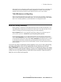
Unpack the Package
Before you begin the installation of Ether-FSH2400NS Fast Ethernet Switch, make sure that you
have all the necessary accessories that come with your package. Follow the steps below to unpack
your package contents:
1.
2.
3.
Clear out an adequate space to unpack the package carton.
Open the package carton and take out the contents carefully.
Put back all the shipping materials such as plastic bag, paddings and linings into the package
carton and save them for future transport need.
After unpacking and taking out the entire package contents, you should check whether you have got
the following items:
⌧
⌧
⌧
⌧
Ether-FSH2400NS Fast Ethernet Switch
One AC power cord
Rack-mounting kit (screws and mounting brackets)
Support CD-ROM (The PDF version of this User’s Manual can be found within)
If any of these above items is missing or damaged, please contact your local dealer for replacement.
Fig. 2-1 Package Contents
4
Ether-FSH2400NS Fast Ethernet Switch
User’s Manual V1.0
2 Preparation before Installation
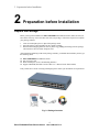
The Front Panel
The front panel is where you can find the twenty-four 10/100Mbps station ports and the LED
indicators. For the technical specifications of the ports, please refer to Appendix A, Product
Specifications for detailed information. For information concerning LED indicators, please refer to
Chapter 4, LED Indicators.
Power LED
Station Ports
Station Port LEDs
DIAG LED
Fig. 2-2 Front Panel
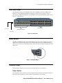
Reset Button
The Ether-FSH2400NS Features a reset button that can restore the switch settings back to factory’s
default value. Please press this button if your management software have problem detecting the
switch or if the switch is not functioning correctly. The reset button is located on the right side of the
front panel
Fig 2-3 The Reset Button
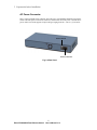
The Rear Panel
The rear panel is where you can locate the power switch and AC power connector.
Power Switch
You can turn the power switch on /off to activate/deactivate the Switch. To turn on the Switch, press
the switch to the ON position. To turn off, press the switch to the OFF position.
5
Ether-FSH2400NS Fast Ethernet Switch
User’s Manual V1.0
2 Preparation before Installation
AC Power Connector
This is a three-pronged power connector where the power cord should be attached. Just plug the
female end of the power cord into the connector, and the male end of the power cord into an AC
power outlet. The switch supports an input voltages ranging from 100 ~ 240 VAC @ 50~60 Hz .
Power Switch
Power Connector
Fig. 2-4 Rear Panel
6
Ether-FSH2400NS Fast Ethernet Switch
User’s Manual V1.0
3 Installation of the Switch
3
Installation of the Switch
Quick Installation
Ether-FSH2400NS Fast Ethernet Switch is fully compliant with 10/100BASE-TX Fast Ethernet
standards.
5 Steps to Quick Installation
Step 1. Power on the Switch.
Step 2. Connect network devices to the Switch: connect either workstation, server, switch, bridge
or router to the station port (10/100BASE-TX), using 100 ohm unshielded twisted pair (category 5
UTP) or shielded twisted-pair (STP) cable.
Step 3. Install the Management software: Please refer to chapter 5 for detail instruction on how to
install and configure the management software.
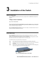
Rack Mounting
Ether-FSH2400NS Fast Ethernet Switch can also be mounted on a standard size 19-inch rack,
which can in turn be placed in a wiring closet with other equipments.
Before you can mount the switch on the rack, first you must attach the mounting brackets on both
sides of the switch with screws, and then mount it as a unit on the rack.
To mount the unit on a rack, please follow the steps below:
Step 1.
Step 2.
Step 3.
Step 4.
First, align the holes on the bracket with the holes on both side of the switch.
Insert screws into the holes and then fasten the bracket on one side of the switch with a
screwdriver.
Repeat Step 1 and 2 to fasten the bracket on the other side of the switch.
Mount the unit on the rack and align the notches on both brackets with mounting holes
on the rack, and then secure the unit with suitable screws.
Fig. 3-1 Fastening the brackets on the switch
7
Ether-FSH2400NS Fast Ethernet Switch
User’s Manual V1.0
2 Preparation before Installation
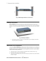
Fig. 3-2 Attaching the Switch to a 19-inch rack
Desktop Installation
Ether-FSH2400NS Fast Ethernet Switch has four rubber pads attached on each corner of its
underside. These pads serve as cushionings against vibration and prevent the switch from sliding off
its position. They also allow adequate ventilation space when you place the switch on top of another
device.
Fig. 3-3 Desktop installation
•
The location you choose to install your switch and the way you configure your network
may greatly affect its performance.
Installation Site Preparation
You can mount Ether-FSH2400NS Fast Ethernet Switch either on desktop or on a 19-inch rack. If
you plan to mount the switch on desktop, please choose a steady, level surface in a well-ventilated
area that is free from excessive dust. In any case, the installation site chosen for your switch has to
comply with the following requirements:
•
•
•
The surface where you want to mount the switch must be able to sustain at least 2.7 kg.
Do not place heavy objects on top of the switch.
The location must preferably be free from excessive dust, away from heat vent, hot-air exhaust
and direct sunlight.
8
Ether-FSH2400NS Fast Ethernet Switch
User’s Manual V1.0
3 Installation of the Switch
•
•
•
•
•
The switch should not be placed near large electric motors or other strong electromagnetic
sources. As a reference, the strength of the electromagnetic field on site should not exceed the
(RFC) standards for IEC 801-3, Level 2(3V/M) field strength.
The air temperature in the location should be within a range of 32 to 122 °F (0 to 55°C).
The relative humidity in the location should not exceed 95% non-condensing humidity.
The distance between the RJ-45 port and the standard network interface should not exceed 100
meters.
Adequate space should be allowed in front of all the ports, so that each port is easily accessible
for cable connections.
Cabling Guide
For 10/100BASE-TX ports
The 24 RJ-45 station ports require Cat. 5 twisted-pair UTP/STP cable for connection. When
configuring within the 10/100BASE-TX cabling architecture, the cable distance should be within
100m.
The following table summarizes the cable requirement for 10/100BASE-TX connection:
10BASE-T
100BASE-TX
100 ohm Category 3, 4, 5 UTP/STP cable
100 ohm Category 5 UTP/STP cable
Auto MDI/MDI-X function
The SNMP-FSH2400NS is equipped with Auto-MDI/MDI-X function, which allows you to use
straight-thru cable even when connecting to another switch/hub. Simply use the straight-through
cable for all types of 10/100BASE-TX connections, either to a PC or to a networking device such as
other hub or switch.
Connection
10 /100Base-TX
Ports
Specification
Interface
Cable to Use
To an end station
To a hub/switch
Maximum Distance
RJ-45
Straight-through twisted-pair cable
Straight-through twisted-pair cable
100 meters
Table 2-2 Cabling type for 10/100BASE-TX
Making your own UTP/STP cable
9
Ether-FSH2400NS Fast Ethernet Switch
User’s Manual V1.0
2 Preparation before Installation
The twisted-pair cable provided an eight-pin plug at each end that mate with the twisted-pair port on
the adapter and with a RJ-45 wall jack. If you are marking your own interface cables to use as
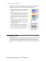
dedicated network wiring or as extension cables, please follow the guideline below:
Each UTP/STP cable contains eight wires in either 568A or
568B color scheme (please see Fig 2-7). The wires are
twisted in pairs to reduce cross talk and various signal
noises.
Each pairs composed of one positive wire and one negative
wire. The positive are marked by stripe color while the
negative are marked by solid color. A pair of wires is
composed of one stripe and one solid wire of the same color.
There are four pairs of wires, they are in group of {1 and 2},
{3 and 6},{4 and 5},{7 and 8}. Please see Fig 2-8 for
diagram.
When making a cable, make sure the correct pairs of wire are
twisted together before inserting into the jack. Incorrect
twisted pair will cause the cable to malfunction or signal
degradation over short distance.
A straight-thru cable have jacks on both end following
the same color scheme.
A cross-over cable have jacks on both end following the
opposite color scheme (one 568A and one 568B)
While 10/100Base-TX only use the first 2 pairs of wires
(1+2, 3+6). However, please still make sure all 4 pairs
are twisted and insert into the jack in correct order.
Fig 2-3 Twisted Pair
Color Scheme
Fig 2-4 Pair Wires
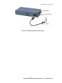
Connecting to Power
Ether-FSH2400NS Fast Ethernet Switch features a universal auto-select power supply unit, which
allows a power connection to a wide range of input voltages from 90 to 240VAC @ 50 ~ 60Hz.
To establish its power connection, simply plug the female end of the power cord into the power
connector on the rear of the switch and the male end of the power cord into a suitable power outlet.
Once you have correctly plugged in the power, you can then turn on the Power Switch to activate the
switch.
10
Ether-FSH2400NS Fast Ethernet Switch
User’s Manual V1.0
3 Installation of the Switch
Power Switch
Power Connector
Power Outlet
Fig 3-13 Connecting the Switch to power outlet
11
Ether-FSH2400NS Fast Ethernet Switch
User’s Manual V1.0
4 LED Indicators
4
LED Indicators
Before connecting any network device to Ether-FSH2400NS Fast Ethernet Switch, you should take
a few minutes to look over this chapter and get familiar with the front panel LED indicators of your
Switch.
System LEDs
-
Power (green) to indicate power on/off status
-
Loop (yellow) to indicate network loop has formed inside the network. You can use
the management program’s diagnostic function to find out which port the loop occurs.
This function will work only after you enabled the Loop Detection using the
Management Utility.
-
Trunk (RED) indicate when the Trunking function is enabled using the management
utilty
Station Port LEDs
For port 1 ~ port 24
- Link/Act (green) to indicate linking status and activity
- FDX/Col (yellow) to indicate Full Duplex transmission mode and collision status
- 100 M LED (red) to indicate 100 Mbps speed
12
Ether-FSH2400NS Fast Ethernet Switch
User’s Manual V1.0
4 LED Indicators
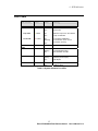
LED Table
LED indicator
Color
Status
Meaning
System LEDs
Power LED
● Green
ON
OFF
Power ON
Power OFF
Loop LED
● Yellow
ON
OFF
Detect a loop even in the network
Loop not detected
Trunk LED
● Yellow
ON
Flashing
Trunk link is established
Trunk function is turn on but
connection is wrong
OFF
Station Port
LEDs
Link/Rx
● Green
ON
Blinking
OFF
Connection is made
Transmitting/Receiving
No connection is made
FDX/Col
● Yellow
ON
Blinking
OFF
Full Duplex
Collision (in half duplex)
Half Duplex
100M
● Red
ON
OFF
100Mbps speed
10Mbps speed
Table 4-1 System & Station Port LEDs
13
Ether-FSH2400NS Fast Ethernet Switch
User’s Manual V1.0
5 Management Software Guide
5
Management Software Guide
Introduction
The Airlive Windows remote management software allows user to configure the management
function though the LAN port. It uses a specialized RRCP protocol and does not use the IP protocol.
It operates inside the Ethernet network. Comparing to the Ether-FSH2400R, the Ether-FSH2400NS
includes a memory management unit (MPU) to allow switch settings be stored inside the flash
memory and enable the authentication key function.
Important Information
WinPCap 3.1 (included in the CD) must be installed before using the management software
Most of the setting options show up when you right click on the screen using your mouse.
Please make sure to press the “Apply” button after changes
Please make sure to “write to the switch” after change settings
The Ether-FSH2400NS has a factory reset button on the right side of the front panel. This
button will restore switch’s setting to factory’s default values.
If your management program can’t find the switch, please press the reset button.
Minimum system requirements
To use Remote Management Application, it is necessary that your system include the following
components:
Hardware
Pentium class processor
128 MB RAM
Software
Windows® 98 SE, Win2000, or WinXP
WinPCap 3.1 (included in the CD)
14
Ether-FSH2400NS Fast Ethernet Switch
User’s Manual V1.0
5 Management Software Guide
Installing the Software
Please follow the procedures below to install the management program into your Windows
1.
Insert the Airlive CD into your computer, the Product CD menu should show up automatically.
If not, on the File Explorer, please click on “setup.exe” to begin.
2.
Click on “ETHER/SNMP Series” and select the “Ether-FSH2400NS”
3.
Follow the instruction on screen to install the “WinPCap”. You only have to install it once. If
you installed WinPCAP 3.0 before, please remove it. Then install the one that is included on
the CD.
4.
After this you can click on the “Management Utility” on the CD to start the management
software.
15
Ether-FSH2400NS Fast Ethernet Switch
User’s Manual V1.0
5 Management Software Guide
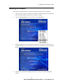
Starting the Software
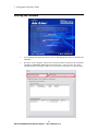
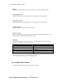
1.
To start Management Application, please click on “Run Management Software” button on the
CD-ROM
2.
The follow screen will appear. Please select a network interface card (choose the one that has
a IP address) and select a switch from the pull down menu. After you select, the switch
configuration menu will appear. Make sure your switch is turned on before using the utility.
16
Ether-FSH2400NS Fast Ethernet Switch
User’s Manual V1.0
5 Management Software Guide
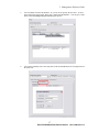
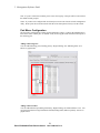
3.
You can add the switch to the database. So you can access quickly the next time. To do so,
please right click on the switch. Then select “Add to Switch Database”. You can give a name
to the switch and change the password during the process.
4.
You can also manually enter a switch by click on the Switch Database tab. Then right click on
the white area.
17
Ether-FSH2400NS Fast Ethernet Switch
User’s Manual V1.0
5 Management Software Guide
There are 4 major functions on the management screen “Network”, “Switch Status”, “Switch
Configuration”, and “Switch Internals”. We will discuss them in the following sections. Please
make sure to save to the hardware after changes.
Switch Status Functions
Click on the Switch Status Tab of the management screen will bring you the overview, port status,
and MIB counter sub menus.
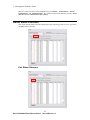
Port Status Submenu
18
Ether-FSH2400NS Fast Ethernet Switch
User’s Manual V1.0
5 Management Software Guide
The port status includes port type, enabled status, link status, speed duplex, flow control, loop
detection, and the “Router Port” for the IGMP function.
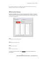
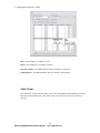
MIB Information Submenu
The function of the MIB counter is to let users see the ongoing traffic of each port. Users can set to
monitor the Transmitting (TX), Receiving (RX), and diagnostic packets separately. Furthermore,
you can even choose to monitor all packets or just collision/error packets. Please remember to right
click each port to change units.
Start
Press this button to start counting packets
Stop
Press this button to stop Byte count
Clear
To clear the current content
Pause
Pause to see the current result.
To Change the Unit or Packet Type. Please right click on any of the ports and make your
selection below:
19
Ether-FSH2400NS Fast Ethernet Switch
User’s Manual V1.0
5 Management Software Guide
Byte: The unit display is in number of bytes
Packet: The unit display is in number of packets
CRC Error Packet: The MIB information show the number of CRC Error
Collision Packet: The MIB information show the number Collision Packet.
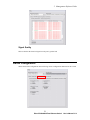
Cable Tester
The “cable tester” function tests the quality of the cable and whether the cable length has exceed the
limit that can be handled by the switch. Please make sure at least one of the port is connected
correctly.
20
Ether-FSH2400NS Fast Ethernet Switch
User’s Manual V1.0
5 Management Software Guide
Signal Quality
This test whether the electrical signal on each port is good or bad.
Switch Configuration
Choose the Switch Configuration menu will bring various configuration submenus for the switch.
21
Ether-FSH2400NS Fast Ethernet Switch
User’s Manual V1.0
5 Management Software Guide
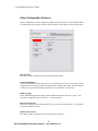
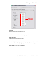
Global Configuration Submenu
Global Configuration is used to configure the global port control registers. Press the Refresh button
to read the status of the registers. Press the Update button to set the registers as shown in this frame.
Broadcast Flow
This define whether to enable flow control for the broadcast packet
Loop Port Detection
You must enable this option first before the “Loop” LED function will work. If you want to use the
loop detection function, please enable this option and save settings to the switch. Once this function
is enabled, the Loop LED will light up when there is a loop formed in your network.
IGMP Snooping
Setting IGMP Snooping Control register and IP Multicast Router Port Discovery register. The
router port is displayed in the Switch Status -> Port Status menu.
Broadcast Storm Filter
The Switch will filter out the broadcast packets once it exceeds 5% of total traffic. You can choose
to enable or disable this option
Multicast Flow Control
This define whether to enable flow control for the multi-cast packet
22
Ether-FSH2400NS Fast Ethernet Switch
User’s Manual V1.0
5 Management Software Guide
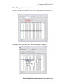
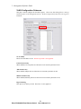
Port Configuration Submenu
Press the “Port Configuration” submenu, and you will see a dialog like follows. Put the check in the
item you want to configure.
To Configure, please right click on a port. Then the following menu will appear!
23
Ether-FSH2400NS Fast Ethernet Switch
User’s Manual V1.0
5 Management Software Guide
Enable:
The default is to enable the port. Check the “Disable” if you want to disconnect the port
Tx Bandwidth Control
Enable this function will restrict the given port’s sending speed to the selected value.
Rx Bandwidth Control
Enable this function will restrict the give port’s receiving speed to the selected value
Advertised Speed
Changing the speed and duplex mode of a given port.
Pause Flow Control
Enable or Disable the pause frame from control. The default is enabled for both RX/TX. This
option needs to be enabled for the Rate Control to work.
Trunking
Enable the Trunking group for this particular port. Trunking combines multiple ports into one
single port. The Trunk group table is as followed:
Group
Trunk 0
Trunk 1
Trunk 2
Trunk 3
Trunk 4
Trunk 5
Ports
1, 2, 13, 14
3, 4, 15, 15
5, 6, 17, 18
7, 8, 19, 20
9, 10, 21, 22
11, 12, 23, 24
*Please make sure to press “Apply” after making changes.
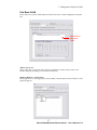
Qos Configuration Submenu
Qos Configuration is used to configure the Qos control registers.
24
Ether-FSH2400NS Fast Ethernet Switch
User’s Manual V1.0
5 Management Software Guide
Right Click on
a port to make
changes
Port Priority
Please right click on a port to change the priority Level
Diffserv Priority
This define whether to use IP Diffserv as the basis for priority contrl
Adapter Flow Control
To disable or enable using the adapter flow control
High/Low Piority Ratio
The number of high priority packet passed, before letting a low priority packet go. For example, if
the ratio is 4:1. That means for every 4 high priority traffic, 1 low priority is allowed to pass.
*Please remember to press “Apply” to make changes.
25
Ether-FSH2400NS Fast Ethernet Switch
User’s Manual V1.0
5 Management Software Guide
VLAN Configuration Submenu
This page is used to configure the vlan table registers. *Please note that although there is 802.1Q
VLAN tag option on the management software. We do not support this feature due to the register’s
limitation.
VLAN Ability
Please select Port-Base VLAN. The 802.1Q VLAN is not supported.
Unicast Packet Leaky
When enabled, Uni-Cast packets are allowed to travel outside a particular VLAN
ARP Packet Leaky
When enabled, ARP packets are allowed to travel outside a particular VLAN
Multicast Packet Leaky
When enabled, Multicast packets are allowed to travel outside a particular VLAN
Ingress Filtering
This option is for 802.1Q VLAN. Therefore, it is not supported.
26
Ether-FSH2400NS Fast Ethernet Switch
User’s Manual V1.0
5 Management Software Guide
Port Base VLAN
Please make sure you have enabled the port based VLAN in the “VLAN configuration” submenu
first.
Right Click to
add a new
VLAN
ADD A New VLAN
Please “right click” your mouse on the white area to add a new VLAN. Once you do, a new
windows will pop-out asking you to select the VLAN ports.
Modify or Remove a VLAN Group
Please right click on a VLAN group you want to modify. Then the option to edit or delete a VLAN
group will pop out.
27
Ether-FSH2400NS Fast Ethernet Switch
User’s Manual V1.0
5 Management Software Guide
Note: If a port is selected as a member port in a new VLAN group. This port will be removed from
the default VLAN group 01.
Note2: If you have mis-configured the VLAN and you can not enter into the switch’s management
utility. Please press the reset button on the left side of the front panel to factory reset the switch.
Port Mirror Configuration
The port mirror configuration is mainly used for diagnostic purpose. It allows the administrator to
listen to the traffic of other ports. In another words, it will copy the traffic from the mirrored port to
the mirroring port.
Adding a Mirroring Port
You can add a Mirroring port (Listening port) by “Right Clicking” the “Mirroring Ports” area.
Please see graph below
Adding a Mirrored Port
You can add a Mirrored port (Being listened) by “Right Clicking” the “Mirrored Ports” area. You
can choose the RX(receiving traff) Mirror and TX(sending traffic) Mirror separately. Please see
graphic below.
28
Ether-FSH2400NS Fast Ethernet Switch
User’s Manual V1.0
5 Management Software Guide
*Please remember to press Apply after making changes.
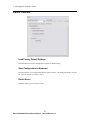
Security Configuration
This page allow administrators to control which port can do the management function. If you want
to change the administration password for the switch, please see page 17 Network ->Add Switch
menu for more details.
Please right
click a port to
disable/enable a
port from
management
29
Ether-FSH2400NS Fast Ethernet Switch
User’s Manual V1.0
5 Management Software Guide
Switch Internals
Load Factory Default Settings
Press this button to reset the configurations to factory’s default settings
Save Configuration to Hardware
Press this setting to save configurations into the switch’s memory. The management utility will also
ask you to do so when you want to close it.
Device Reset
Press this setting to power reset the switch.
30
Ether-FSH2400NS Fast Ethernet Switch
User’s Manual V1.0
Appendix A Product Specifications
Ether-FSH2400NS Fast Ethernet Switch
Appendix A Product Specifications
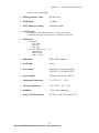
•
Standard Compliance
IEEE 802.3 10BASE-T Ethernet
IEEE 802.3u 100BASE-TX Fast Ethernet
IEEE 802.1q VLAN standard
IEEE 802.1p Class of Service
IEEE 802.1ad Link Aggregation
ANSI/IEEE Std 802.3 NWay auto-negotiation
•
Topology
•
Port Configuration
Star
24 × 10/100 BASE-TX Port
Auto MDI/MDI-X
•
Data Rate
10BASE-T Ethernet
10 Megabits/sec (half-duplex)
20 Megabits/sec (full-duplex)
100BASE-TX Fast Ethernet
100 Megabits/sec (half-duplex)
200 Megabits/sec (full-duplex)
•
Trunking: up to 7 trunk groups in 2, 4, or 8 port group
•
VLAN
Port Based
VLAN filtering rules
•
Priority (QoS) Types
VLAN based
TCP/IP TOS
Per Port
•
Priority Level
2-level: High/Low
•
Transmission method
Store and Forward
•
Full Duplex
Auto-negotiation
•
Active Flow Control
IEEE 802.3x compliant flow control for full duplex
31
Ether-FSH2400NS Fast Ethernet Switch
User’s Manual V1.0
Appendix A Production Specifications
Back Pressure for half duplex
•
Filtering Address Table
8 K per device
•
RAM Buffer
2.5 Mbits
•
MAC Address Learning
Automatic update
•
Cabling Type
10BASE-T: 4-pair 100 ohm Category 3,4,5 UTP (100 m) cable
100BASE-TX: 4-pair 100 ohm Category 5 UTP/STP (100 m) cable
•
LED layout
System LEDs
Power LED
Loop LED
Trunk LED
Station port LEDs for port 1 ~ 24
Link/Act LEDs
FDX/Col LEDs
100M
LEDs
•
Dimensions
330 × 162 × 44 mm.
•
Net Weight
1.6 kg
•
Power Input
Internal universal power supply,
100~240 VAC, 50~60 Hz, 0.4A
•
Power Output
10 Watts max, @ 100 ~ 240 VAC
•
Operating Temperature
32 ~ 122 °F / 0 ~ 50 °C
•
Storage Temperature
- 40 ~ 149°F / -40 ~ 65 °C
•
Humidity
< 95% (non-condensing)
•
Safety / EMI Certificates
UL, TUV, VDE, FCC Class A, CE
32
Ether-FSH2400NS Fast Ethernet Switch
User’s Manual V1.0
Appendix B Troubleshooting
Appendix B Troubleshooting
This appendix contains specific information to help you identify and solve problems.
If your switch does not function properly, please make sure it is set up according to
the instructions on the manual.
If you suspect your switch is not connected correctly to your network, check the
following points before you contact your local dealer for support.
•
•
•
•
•
•
•
•
•
Make sure the Power is ON (Check the Power LED).
Make sure the cable is connected properly on both ends.
Make sure that the maximum cable length between switch and end node
does not exceed 100 meters (for 10/100BASE-TX connection).
Make sure that the maximum switch-to-hub/switch cable distance does not
exceed 100 meters (for 10/100BASE-TX connection).
Verify that the cabling type used is correct.
Check the corresponding Link/Act, FDX/Col, 100M for signs of faulty
connection. Check the status of the cable attachment. If the problem
persists, try a different cable.
Try another port on the Switch.
Turn off power supply to the Switch. After a while, turn it on again to see if
it resumes to its normal function.
If you find out where the problem is but cannot solve it by yourself, or you
simply cannot locate what is at fault, please contact your local dealer for
technical support.
33
Ether-FSH2400NS Fast Ethernet Switch
User’s Manual V1.0