1
NetBlazer LS
Installation and
Setup Utility Guide
Part Number 90362-01
Revision A0
TELEBIT CORPORATION SOFTWARE LICENSE AGREEMENT
License. This software (the "Software") and related documentation are licensed to you by
Telebit Corporation (“Telebit”). Both the Software and the documentation are protected
under applicable copyright laws, international treaty provisions and trade secret statutes of
various states. This License Agreement grants you a non-exclusive and non-transferable
license to use the Software for your internal purposes solely in conjunction with the replacements, accessories, spare parts and upgrades listed on Telebit's current product price
list ("Equipment"). This is not an agreement for the sale of the Software or the documentation or any copy of the Software or the documentation and you have not acquired title or
ownership in the Software or the documentation or any copies or part thereof. Your right
to use the software and the documentation is subject to the following further terms and conditions: i) Any Software, including any subsequent updates as provided herein, is licensed
solely in object code form for internal use only in connection with the associated Equipment purchased by you pursuant to this Agreement. You shall pay Telebit's prevailing license fee (less any applicable discount) for each copy of any Software package licensed by
you; ii) You may obtain updates to such Software which Telebit makes generally available
for licensing on the associated Equipment, provided you obtain a license for each such updates from Telebit at Telebit's then prevailing fee; iii) You shall not provide, disclose or
otherwise make available the Software in any form to any person other than your employees without Telebit's prior written consent, except when any such person is on your premises and under your direction and control for purposes specifically related to your
permitted use of the Software.
You may make one (1) copy of any Software licensed from Telebit solely for back up or
archival purposes, provided you reproduce and include Telebit's copyright and other proprietary rights notices on and in any such copy. Any copy which you make of the Software,
in whole or in part, is the property of Telebit.
Restrictions. Telebit reserves all rights not expressly granted to you by this License
Agreement. The Software contains copyrighted materials, trade secrets, and other proprietary information and in order to protect them you may not copy, reproduce, modify, reverse assemble, reverse compile or otherwise reverse engineer or create derivative works
of the Software in whole or in part. For information regarding interoperability, write:
Telebit Corporation, One Executive Drive, Chelmsford, MA 01824, Attn: Technical Support Department. You agree to take appropriate action by instruction, agreement or otherwise with your employees or other persons allowed access to the Software to satisfy its
obligations under this Agreement with respect to the use, copying, modification, disclosure,
protection and security of the Software. You must have a reasonable mechanism or process
to ensure that the number of users at any one time does not exceed the number of licenses
you have paid for and to prevent access to the Software to any person not authorized under
the above license to use the Software. Your license to use the Software and documentation
will automatically terminate if you fail to comply with the terms of this License Agreement.
If this license is terminated you agree to destroy all copies of the Software and documentation in your possession.
90362-01
i
TELEBIT CORPORATION LIMITED WARRANTY
Limited Warranty on Media. Telebit warrants to the original licensee that the media on
which the Software is recorded will be free from defects in materials and workmanship under normal use for a period of ninety (90) days from the date of delivery. Telebit's entire
liability and your exclusive remedy pursuant to this limited warranty shall be limited to replacement of the defective media. If failure of the media has resulted from accident, abuse
or misapplication of the product, Telebit shall have no responsibility to replace the media
under this limited warranty.
Disclaimer of Warranty on Software. The Software and related documentation are provided "AS IS" and without warranty of any kind. TO THE EXTENT PERMITTED BY
LAW, TELEBIT EXPRESSLY DISCLAIMS ALL WARRANTIES, EXPRESS OR IMPLIED, INCLUDING BUT NOT LIMITED TO THE IMPLIED WARRANTIES OF
MERCHANTABILITY AND FITNESS FOR A PARTICULAR PURPOSE. TELEBIT
DOES NOT WARRANT THAT THE FUNCTIONS CONTAINED IN THE SOFTWARE
WILL MEET YOUR REQUIREMENTS, OR THAT THE OPERATION OF THE SOFTWARE WILL BE UNINTERRUPTED OR ERROR-FREE, OR THAT DEFECTS IN
THE SOFTWARE WILL BE CORRECTED. FURTHERMORE, TELEBIT DOES NOT
WARRANT OR MAKE ANY REPRESENTATIONS REGARDING THE USE OR THE
RESULTS OF THE USE OF THE SOFTWARE OR RELATED DOCUMENTATION IN
TERMS OF THEIR CORRECTNESS, ACCURACY, RELIABILITY, OR OTHERWISE.
NO ORAL OR WRITTEN INFORMATION OR ADVICE GIVEN BY TELEBIT OR A
TELEBIT AUTHORIZED REPRESENTATIVE SHALL CREATE A WARRANTY OR
IN ANY WAY INCREASE THE SCOPE OF THIS WARRANTY.
TELEBIT SHALL IN NO EVENT BE LIABLE FOR ANY SPECIAL, COLLATERAL,
INCIDENTAL OR CONSEQUENTIAL DAMAGES INCLUDING WITHOUT LIMITATION ANY CLAIM FOR LOST OR DAMAGED DATA, NETWORK DOWN TIME OR
DEGRADED PERFORMANCE, LOST PROFITS OR LOSS OF GOODWILL. In no
event shall Telebit's total liability to you for all damages, losses and causes of action
whether in contract, tort (including negligence) or otherwise exceed the amount paid by
you for the Software.
U.S. GOVERNMENT RESTRICTED RIGHTS
The Software and documentation are provided with RESTRICTED RIGHTS. Use, duplication, or disclosure of the Software by the U.S. Government is subject to restrictions as set
forth in subdivision (c) (1) of the Rights in Technical Data and Computer Software clause
at 252.227-7013. Use, duplication, or disclosure of the Technical Data by the U.S. Government is subject to restrictions as set forth in subdivision (b) (3) of the Rights in Technical
Data and Computer Software clause at 252.227-7013. Use, duplication, and disclosure by
the governments of any other countries is subject to restrictions to similar applicable laws.
The parties hereto agree that the United Nations Convention on the International Sale of
Goods shall not apply to this License agreement.
ii
90362-01
General. This License shall be governed by and construed in accordance with the laws of
the Commonwealth of Massachusetts, excluding its conflict of law rules, and shall inure to
the benefit of Telebit, its successors, representatives and assigns. The license granted hereunder may not be assigned, sublicensed or otherwise transferred by you. If any provisions
of this Agreement shall be held to be invalid, illegal or unenforceable, the validity, legality
and enforceability of the remaining provisions shall in no way be affected or impaired
thereby.
For more information about Telebit’s licensing policies, write: Telebit Corporation, One
Executive Drive, Chelmsford, MA 01824, Attn: Contract Administrator.
Trademarks
Telebit, NetBlazer, and TrailBlazer are trademarks of Telebit Corporation.
Telebit gratefully acknowledges the following additional copyrights:
•
Apple, AppleTalk, and LocalTalk are registered trademarks of Apple Computer,
Inc.
•
Novell and NetWare are registered trademarks of Novell, Inc.
•
UNIX is a registered trademark of AT&T Bell Laboratories.
•
TCL is copyrighted by the University of California, Berkeley (unrestricted
redistribution).
Other brands or product names are trademarks of or registered trademarks of their
respective holders.
Installation Safety Guidelines
Follow these guidelines when installing your NetBlazer:
90362-01
•
Never install telephone wiring during a lightning storm.
•
Never install telephone jacks in wet locations unless the jack is specifically
designed for wet locations.
•
Never touch non-insulated telephone wires or terminals unless the telephone
line has been disconnected at the network interface.
•
Use caution when installing or modifying telephone lines.
•
Avoid using a telephone (other than a cordless type) during an electrical storm.
There may be a remote risk of electric shock from lightning.
•
Do not use the telephone to report a gas leak in the vicinity of the leak.
iii
Power Cord
The NetBlazer LS I-1BS and NetBlazer LS 2S/A can be used only with a power cord that
meets the rating of the unit, that is, 1.5A/250V. THE POWER CORD MUST BE APPROVED ACCORDING TO THE STANDARDS OF THE COUNTRY IN WHICH THE
UNIT IS USED. Telebit is not responsible for damages or losses caused by the use of the
unit with an underrated, nonstandard, and unapproved power cord.
Bitte, verwenden Sie nur ein zugelassenes Netzanschlußkabel.
FCC Warning
This equipment generates and uses radio frequency energy, and if not installed and used in
strict accordance with the instructions in this manual, may cause interference to radio and
television reception. It has been tested and found to comply with the limits for a Class A
computing device under Part 15 of FCC Rules, which are designed to provide reasonable
protection against such interference in a commercial installation. However, there is no
guarantee that interference will not occur in a particular installation. If this equipment does
cause interference to radio or television reception, which can be determined by turning the
system on and off, the user is encouraged to try to correct the interference by one or more
of the following measures:
•
Reorient the receiving antenna.
•
Relocate the system with respect to the receiver.
•
Move the system away from the receiver.
•
Plug the system into a different outlet so that the system and receiver are on different branch circuits.
If necessary, consult your dealer or any experienced radio/television technician for
additional suggestions. You may find a booklet prepared by the FCC entitled How to Identify and Resolve Radio-TV Interference Problems helpful in resolving any problems. This
booklet is available from the U.S. Government Printing Office, Washington DC 20402,
Stock Number 004-000-00345-4.
Emissions Statement
This equipment has been tested and found to comply with the limits of CISPR22 Class B,
EN55022 Class B, and FCC Part 15 Class B.
Canadian Emissions Standards
Le présent appareil numérique n’émet pas de bruits radioélectriques dépassant les limites
applicables aux appareils numériques de la class B prescrites dans le Règlement sur le
brouillage radioélectrique édicté par le ministére des Communications du Canada.
iv
90362-01
Table of Contents
1. Getting Started ................................................................................ 1-1
NetBlazer Applications................................................................................. 1-1
Configuration Flowchart............................................................................... 1-4
2. NetBlazer LS Installation................................................................ 2-1
Dual DTE Installation................................................................................... 2-1
ISDN Installation .......................................................................................... 2-2
NetBlazer Front Views ................................................................................. 2-3
LED Activity............................................................................................ 2-4
Dual-DTE LEDs ................................................................................ 2-4
ISDN LEDs........................................................................................ 2-5
Equipment Requirements.............................................................................. 2-5
Terminal to NetBlazer LS Connection .................................................... 2-6
Computer (25 pin) to NetBlazer LS Connection ..................................... 2-6
Computer (9 pin) to NetBlazer LS Connection ....................................... 2-7
Modem to NetBlazer LS Connection....................................................... 2-7
DSU or TA RS-232 Connection to NetBlazer LS (ISDN or Dual DTE) 2-7
DSU or TA RS-449 Connection to NetBlazer LS (Dual DTE only)....... 2-8
DSU or TA V.35 Connection to NetBlazer LS (Dual DTE only) ........... 2-8
DSU or TA X.21 Connection to NetBlazer LS (Dual DTE only) ........... 2-8
NT1 Connection to NetBlazer LS (ISDN only)....................................... 2-9
Power Requirements..................................................................................... 2-9
ISDN Requirements...................................................................................... 2-9
3. Using the Setup Utility.................................................................... 3-1
Establishing a Terminal Connection............................................................. 3-3
Direct Null-modem Connection............................................................... 3-4
Telnet to NetBlazer’s Default Address .................................................... 3-5
AppleTalk Data Stream Protocol (ADSP) Connection............................ 3-6
Dial-in Connection to Remote NetBlazer ................................................ 3-7
Starting the Setup Utility .............................................................................. 3-7
Working on the Main Menu Screen............................................................ 3-10
90362-01
v
Moving Around and Entering Data ............................................................ 3-12
Moving Around...................................................................................... 3-12
Entering and Editing Data...................................................................... 3-12
Text Fields ....................................................................................... 3-13
List Fields......................................................................................... 3-15
Choice Fields ................................................................................... 3-16
Working on the Save/Exit Screen............................................................... 3-16
Getting Online Help.................................................................................... 3-18
First-time User Help .............................................................................. 3-18
On-screen Help Messages...................................................................... 3-19
Context Sensitive Help .......................................................................... 3-19
Full Screen Help .................................................................................... 3-19
4. NetBlazer and LAN Setup ............................................................... 4-1
NetBlazer Setup ............................................................................................ 4-1
NetBlazer LAN Configuration ..................................................................... 4-3
Configuring IP Routing............................................................................ 4-4
Configuring IPX Routing......................................................................... 4-6
Configuring AppleTalk Routing .............................................................. 4-8
Seed Router Configuration .............................................................. 4-10
5. Line Setup ........................................................................................ 5-1
Configuring a Line........................................................................................ 5-1
6. ISDN Connections ........................................................................... 6-1
Configuring an ISDN Connection ................................................................ 6-2
7. Dial-up Connections ....................................................................... 7-1
Configuring a Dial-up Connection ............................................................... 7-2
Setting Balanced Interfaces...................................................................... 7-7
Setting Protocol Details ........................................................................... 7-9
IP Routing Choices ................................................................................ 7-12
8. Dedicated Connections .................................................................. 8-1
Configuring Dedicated LAN-to-LAN Interfaces.......................................... 8-1
Setting Frame Relay Connections............................................................ 8-5
vi
90362-01
9. Dial-In Users .................................................................................... 9-1
Configuring a Dial-in User ........................................................................... 9-2
Configuring Character Mode Users ......................................................... 9-4
Configuring Remote IP Users.................................................................. 9-6
Configuring Remote IPX Users ............................................................... 9-8
Configuring ARA Users .......................................................................... 9-9
10. Modem Pools................................................................................. 10-1
Configuring a Modem Pool ........................................................................ 10-1
11. Registering and Updating ............................................................ 11-1
Registering Your NetBlazer ....................................................................... 11-1
Updating Your Software............................................................................. 11-4
Appendix A.
Configuring for Multiple Protocols............................A-1
Appendix B. NetBlazer LS Configuration Worksheets..................B-1
NetBlazer Name and Password ....................................................................B-4
LAN Setup for IP..........................................................................................B-5
LAN Setup for IPX.......................................................................................B-6
LAN Setup for AppleTalk ............................................................................B-7
Lines .............................................................................................................B-8
ISDN .............................................................................................................B-9
Dial-up LAN-to-LAN Interface..................................................................B-10
Dial-up IP Protocol .....................................................................................B-11
Dial-up IPX Protocol ..................................................................................B-12
Dial-up AppleTalk Protocol .......................................................................B-13
Dedicated LAN-to-LAN Interface..............................................................B-14
Dedicated IP Protocol .................................................................................B-15
Dedicated IPX Protocol ..............................................................................B-16
Dedicated AppleTalk Protocol ...................................................................B-17
Frame Relay Connections...........................................................................B-18
Dial-in IP User............................................................................................B-19
Dial-in IPX User .........................................................................................B-20
Dial-in ARA User .......................................................................................B-21
Dial-in Character Mode User......................................................................B-22
IP Modem Pool ...........................................................................................B-23
NetBlazer Registration................................................................................B-24
90362-01
vii
Appendix C. IP Addressing ............................................................. C-1
Assigning IP Addresses ................................................................................C-2
Setting the Subnet Mask ..........................................................................C-3
Appendix D. IPX Addressing........................................................... D-1
IPX Network Number.................................................................................. D-1
IPX Node Number ....................................................................................... D-1
IPX Internal Network Number .................................................................... D-2
IPX Port Number ......................................................................................... D-2
Appendix E.
AppleTalk Routing...................................................... E-1
AppleTalk LAN Routing ..............................................................................E-1
AppleTalk Zones and NetWork Numbers ....................................................E-1
Network Numbers and Ranges ................................................................E-2
Zones........................................................................................................E-2
Learning and Forgetting Routes ...................................................................E-3
Appendix F.
NetBlazer Backup........................................................F-1
Appendix G. Troubleshooting and Customer Support ................. G-1
General Troubleshooting ............................................................................. G-2
Microsoft Windows Troubleshooting.......................................................... G-3
Setup Utility Troubleshooting ..................................................................... G-3
NetBlazer LS ISDN Troubleshooting.......................................................... G-4
Obtaining Customer Support ....................................................................... G-5
Pre-Call Checklist ................................................................................... G-7
Ordering Additional Documentation ........................................................... G-8
Appendix H. Joining the Global Internet........................................ H-1
Internet Overview ........................................................................................ H-1
Do You Need Your Own Internet Connection? .......................................... H-1
Obtaining an IP Network Number............................................................... H-2
About the InterNIC ................................................................................. H-2
InterNIC Registration Services ............................................................... H-3
Telephone Access ............................................................................. H-3
Email Access..................................................................................... H-3
U.S. Mail Access............................................................................... H-4
Other InterNIC Services ................................................................... H-4
viii
90362-01
Registering a Domain .................................................................................. H-5
Getting a Physical Connection..................................................................... H-5
Choosing a Service Provider ....................................................................... H-6
Tying It All Together................................................................................... H-7
Appendix I.
Key Summary ............................................................... I-1
Appendix J.
ISDN Service Providers
and ManufacturersJ-1
Selecting Your ISDN Service........................................................................J-1
SPIDs and DNs .........................................................................................J-1
DNs and Switches ...............................................................................J-2
Ordering ISDN Service.............................................................................J-2
Long Distance Service Requirements.................................................J-4
ISDN Manufacturers......................................................................................J-4
Appendix K. Telebit Cables and Adapter Pinouts .........................K-1
Standard 25-pin RS-232 Cable (Part No. 14158-01)................................... K-2
DB-9 to DB-25 RS-232 Cable (Part No. 14339-01).................................... K-3
Synchronous RS-232 Cable (Part No. 14358-01)........................................ K-4
Null-Modem Adapter (Part No. 14375-01) ................................................. K-5
Null-Modem Adapter (Part No. 14674-01) ................................................. K-5
RS-449 Cable (Part No. 14385-01) ............................................................. K-6
V.35 Cable (Part No. 14384-01).................................................................. K-7
X.21 Cable (Part No. 14386-01).................................................................. K-8
Appendix L.
Glossary....................................................................... L-1
Index
90362-01
ix
x
90362-01
Getting Started
1
Use this manual together with the Worksheets in Appendix B,
“NetBlazer LS Configuration Worksheets” to install and configure your
NetBlazer for the type of system and applications you have. You should fill
out the Worksheets before you begin the configuration process.
NetBlazer Applications
In order to know which worksheets to fill out (or that your system administrator or service provider should fill out for you), you need to know which
protocols and which related applications you want to configure. Your
choices for configuring your local network and for setting up your applications are interconnected. The following diagrams describe some of the most
common NetBlazer configurations. See Appendix A, “Configuring for Multiple Protocols,” for information on configuring to route multiple protocols.
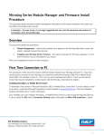
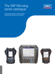
•
LAN-to-LAN routing involves
routing information from one local
area network (LAN) to another local network.
First
Local
Network
NetBlazer LS
Second
Local
Network
Figure 1-1. LAN-to-LAN Routing
A NetBlazer can work with more than one LAN interface to route
packets between Ethernet, AppleTalk, or Token Ring networks.
90362-01
Getting Started
1-1
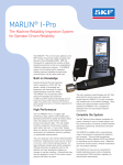
•
Dial-up LAN-to-LAN routing is used to route information between the
local network and a dial-up remote network.
NetBlazer
NetBlazer LS
Your
Local
Network
Modem
The
Remote
Network
Telephone
Network
Modem
Figure 1-2. Dial-up LAN-to-LAN Routing
This application routes packets between NetBlazers on a dial-up
connection over a Public Switched Telephone Network (PSTN) or
an ISDN connection.
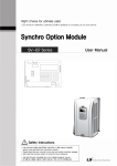
•
Dedicated LAN-to-LAN routing is used to route information between
the local network and a remote network over a dedicated or leased
telephone line.
Your
Local
Network
Dedicated or
leased line
CSU/DSU
The
Remote
Network
CSU/DSU
Figure 1-3. Dedicated LAN-to-LAN Routing
You can set up the NetBlazer as a leased-line router with the unique
ability to automatically establish a dial-up backup connection if the
leased-line connection fails.
1-2
Getting Started
90362-01
•
Dial-up Client-to-LAN routing is used to route information to and
from your local area network and a dial-in user.
Remote User
Your
Local
Network
Modem
Telephone
Network
Modem
Figure 1-4. Client-to-LAN Routing
This application allows remote users to access servers on your local
LAN through a dial-in connection to your NetBlazer.
For example, remote users could login to the NetBlazer and access
files or print servers on the local network, or they could use the
NetBlazer as a terminal server for telnet or dial-out connections.
•
Your
Local
Network
Modem pooling uses
a network modem pool to communicate
between your local network and a remote site, such as a bulletin
board.
The modem
pool address
Figure 1-5. Modem Pooling
This application allows IP LAN users to use the first available
modem without having to check to see which one is available. By
associating an IP address with a pool of modems, a user can telnet to
the address of the pool to have the NetBlazer use the first available
modem.
90362-01
Getting Started
1-3
Configuration Flowchart
The following flowchart shows the major steps you might take to configure
your NetBlazer using the Setup Utility.
1. Fill out any necessary or required worksheets in Appendix B,
“NetBlazer LS Configuration Worksheets.”
2. Turn on the NetBlazer and log on as setup.
3. Set your NetBlazer’s name and password.
4. Set up the “port” configurations:
•
Configure the protocols (IP, IPX, and/or AppleTalk) you want
your Netblazer to use to route information on the LANs attached
to the NetBlazer.
•
If necessary, change the defaults for your lines. You can change a
line from async to sync, for example.
•
If your NetBlazer includes ISDN hardware, configure the
NetBlazer to route over ISDN lines.
5. Configure your NetBlazer to route information using one or more
of the following applications:
•
•
•
•
Dial-up LAN-to-LAN communications
Dedicated LAN-to-LAN communications
Dial-in remote users
Dial-out modem pooling
6. Register your NetBlazer with Telebit.
7. Save your settings and exit the Setup Utility, then back up your
saved configuration.
1-4
Getting Started
90362-01
NetBlazer LS Installation
2
The NetBlazer LS is currently shipped in two models, the LS ISDN (LS
I-1BS) and the LS 2-PT (LS 2S/A), known as Dual DTE. Illustrations of
these model’s back panels are shown in the following sections.
Both models have one LocalTalk port, and one Ethernet port which can use
either a BNC or UTP connection. Both models are shipped with one Ethernet and one LocalTalk adapter pre-installed. You can have a maximum of
two LANs connected to your NetBlazer LS (one Ethernet and one
LocalTalk).
Dual DTE Installation
1. Connect
a null modem cable
from your computer to the
NetBlazer.*
Sync/Async DTE Line 00
Ethernet
MAC Addr
4. Turn
2. Connect any LAN
cables to the LocalTalk or
Ethernet ports.
3. Plug in the
power cable.
Sync/Async DTE Line 01
LocalTalk BNC
UTP
Power
SN
on the power switch.
*Or, if your setup will be done remotely, connect the NetBlazer to a modem
so you can dial in to configure it.
Figure 2-1. Dual DTE Back Panel and Install Instructions
90362-01
NetBlazer LS Installation
2-1
ISDN Installation
1. Connect
a null modem cable
from your computer to the
NetBlazer.*
2. Connect
any LAN cables to the
LocalTalk or Ethernet ports.
3. Plug in the
power cable.
SYNC/ASYNC
ISDN
BRI
Ethernet
MAC Addr
DTE Line 00
LocalTalk BNC
UTP
Power
SN
the
NetBlazer to your
NT1.
5. Connect the NT1 to the
4. Connect
NT1
Telephone company wall
outlet for your ISDN line.
6. Turn
on the power switch.
*Or, if your setup will be done remotely, connect the NetBlazer to a modem
so you can dial in to configure it.
Figure 2-2. ISDN Back Panel and Install Instructions
2-2
NetBlazer LS Installation
90362-01
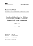
NetBlazer Front Views
Figure 2-3 shows the front panels for both the ISDN and Dual DTE models
of the NetBlazer LS. Both models feature a rocker-type power switch on the
left side of the front panel.
NetBlazer LS 2-PT
S
AN
POWER
PWR
CV
RE
TR
RDY
C
BN
L
CO
AN
P/
TR
UT
ETHERNET
CV
RE
CD
LOCALTALK
SD
RD
CD
DTE A
SD
RD
DTE B
Dual DTE
NetBlazer LS ISDN
S
AN
TR
POWER
PWR
RDY
CV
RE
C
BN
L
CO
P/
UT
ETHERNET
AN
TR
CV
RE
LOCALTALK
CD
SD
RD
DTE
D
B1
B2
BRI
ISDN
Figure 2-3. NetBlazer LS Front LED Panels
Note:
The pinhole to the right of the power switch is used to reset your NetBlazer
to the factory defaults by erasing all saved configuration files. To reset the
NetBlazer, turn the NetBlazer’s power off and insert one end of a straightened paper clip into the pinhole. Holding the paper clip firmly pushed in,
turn the NetBlazer back on and continue to press in on the paper clip for five
or more seconds. When you release the paper clip, the NetBlazer will boot
up using factory default settings.
Both NetBlazer models show PWR (Power) and RDY (Ready) status indicators by the power switch. The PWR LED is on when AC power is applied to
the NetBlazer. The RDY LED is on when the NetBlazer has completed booting up.
90362-01
NetBlazer LS Installation
2-3
The other status indicators light to show activity on the respective channels;
unused channels do not light. The Ethernet status indicators include TRAN
(Transmit), RECV (Receive), COL (Collision), and UTP/BNC (UTP and BNC
ports). The LocalTalk indicators are TRAN and RECV.
For the Dual DTE model, both DTE ports have status lights for CD (Carrier
Detect), SD (Send Data), and RD (Receive Data). The ISDN NetBlazer has
CD, SD, and RD lights for the DTE port, and for the BRI lines has LED lights
for D (D-channel), B1 (first B-channel), and B2 (second B-channel) status
indicators.
LED Activity
When the NetBlazer is first powered on, it performs an automatic Power-On
Self Test (POST). This test consists of a series of hardware exercises that
must be completed successfully before the NetBlazer can begin operation.
Passing the POST test indicates that the NetBlazer is functioning normally.
If an error is detected during POST, the LEDs on the right side of the front
panel turn on in a specific pattern that indicates the type of POST error that
occurred.
Note:
If there is a POST failure, make a note of which LEDs are on before calling
Telebit Technical Support at 1-408-734-5200. The LED information helps
your technical support representative determine the most appropriate
course of action.
When the POST sequence finishes, the NetBlazer loads the software. During loading, the RDY light blinks to indicate activity. Once the software is
loaded, the RDY light stays on continually.
While the NetBlazer is running, the COL light should only blink on rare
occasions. If you see the COL light on very often, there may problem with
data colliding when it is being transmitted. The COL light may also come on
if the Ethernet cables have been disconnected or are not properly
terminated.
Dual-DTE LEDs
The Dual DTE LEDs on the NetBlazer LS display the current status of the
dual port connections. The lights for both DTE A and DTE B indicate the
same information.
2-4
NetBlazer LS Installation
90362-01
If the CD light is on, the Netblazer has detected a telephone connection. If
the CD light goes off, the connection has been lost. If the SD light is on, your
NetBlazer is currently sending data. If the RD light is on, your NetBlazer is
currently receiving data.
ISDN LEDs
The ISDN LEDs on the NetBlazer LS display the current status of ISDN
connections.
If the D LED is steadily on (not blinking) once the NetBlazer has completed
both booting and loading the software, your cables are all connected and you
have an active ISDN connection. If the D light is blinking, the NetBlazer is
trying to connect but a cable may be loose. If the D light is off, you are not
connected for ISDN, either because a cable is unplugged or because the
ISDN line into your site is not active.
The two B lights indicate the status of the two BRI lines into the NetBlazer.
If these lights are off, there is no data being sent or received. If these lights
are blinking, the NetBlazer is setting up a call. If the lights are steadily on,
you have a connection and data is being exchanged.
Equipment Requirements
Each NetBlazer LS model has different equipment requirements. As you
read through the following sections, keep in mind which of the two models
you have.
For both models, you need the following components for the installation:
90362-01
•
NetBlazer LS, AC cord, and power supply
•
25-pin female-to-female null modem adapter (14674-01)
•
ISDN cable WT-MM1430-006 (used to connect the NT1 to the
NetBlazer ISDN BRI port), shipped with ISDN model only.
•
Any additional cables appropriate to the systems and devices that
you are installing. Depending on your setup, you may need to order
cables from Telebit (see Appendix K, “Telebit Cables and Adapter
Pinouts”).
NetBlazer LS Installation
2-5
The following sections show cabling information for all of the possible
NetBlazer LS connections. Look at the following illustrations and find the
ones that relate to your connections to see which cables are needed for those
connections.
Terminal to NetBlazer LS Connection
14375-01 Null Modem
14158-01 RS-232 Cable
DB-25 DB-25
F
M
Terminal
DB-25
DB-25
Null
F
M
NetBlazer LS
DTE
DTE
Computer (25 pin) to NetBlazer LS Connection
14674-01 Null Modem
14158-01 RS-232 Cable
PC (25 pin)
DB-25 DB-25
M
F
DTE
2-6
NetBlazer LS Installation
DB-25
DB-25
Null
M
M
NetBlazer LS
DTE
90362-01
Computer (9 pin) to NetBlazer LS Connection
14674-01 Null Modem
14339-01 RS-232 Cable
PC (9 pin)
DTE
DB-9
M
DB-9
F
DB-25 DB-25
M
F
DB-25
DB-25
Null
M
M
NetBlazer LS
DTE
14158-01 RS-232 Cable
Modem to NetBlazer LS Connection
14158-01 RS-232 Cable
Modem
DB-25 DB-25
F
M
DB-25 DB-25
F
M
DCE
NetBlazer LS
DTE
DSU or TA RS-232 Connection to NetBlazer LS (ISDN or Dual DTE)
14358-01 RS-232 Cable
DSU or TA
DCE
90362-01
DB-25 DB-25
F
M
DB-25 DB-25
F
M
NetBlazer LS
DTE
NetBlazer LS Installation
2-7
DSU or TA RS-449 Connection to NetBlazer LS (Dual DTE only)
14385-01 RS-449 Cable
DSU or TA
DB-37 DB-37
F
M
DB-25 DB-25
F
M
NetBlazer LS
DTE
DCE
DSU or TA V.35 Connection to NetBlazer LS (Dual DTE only)
14384-01 V.35 Cable
DSU or TA
V35
S
V35
P
DB-25 DB-25
F
M
NetBlazer LS
DTE
DCE
DSU or TA X.21 Connection to NetBlazer LS (Dual DTE only)
14386-01 X.21 Cable
DSU or TA
DB-15 DB-15
S
P
DCE
2-8
NetBlazer LS Installation
DB-25 DB-25
F
M
NetBlazer LS
DTE
90362-01
NT1 Connection to NetBlazer LS (ISDN only)
WT-MM1430-006 RJ45 - RJ45 Cable
NT1
RJ48
S
RJ45
P
RJ45
P
RJ48
S
NetBlazer LS
Power Requirements
Your NetBlazer LS is supplied with an autoranging, universal power supply
that automatically adapts itself to your line voltage. Your wall plug should
be a 110v (or 220v) connection. If for any reason you need to know the
power requirements, the NetBlazer LS ISDN (LS I-1BS) requires +5 Volts
DC; the NetBlazer LS 2-PT (LS 2S/A) or Dual DTE requires +5 Volts DC,
+12 Volts DC and -12 Volts DC.
Warning:
The NetBlazer LS is designed to allow connection to LAN and WAN interfaces with the power turned on. However, as a general safety precaution,
turn off the power before making any connections. If the unit is being serviced with the power applied, do not hold or wear any conductive or metallic
objects (for example, screwdrivers, watches, or rings) while making the
LAN and/or WAN connections.
ISDN Requirements
The NetBlazer LS ISDN model provides an integrated point to point Basic
Rate S/T interface.
To install the ISDN NetBlazer you need:
•
90362-01
ISDN phone lines installed at your location.
NetBlazer LS Installation
2-9
•
Note:
An NT1 (Network Terminator of Layer 1). See Appendix J, “ISDN
Service Providers and Manufacturers” for a list of manufacturers.
Only one NetBlazer can be connected to an NT1. Do not connect any additional NetBlazers or any TAs to the NT1 used for the NetBlazer.
Before you can configure ISDN in the NetBlazer LS you must obtain the
following information from your local telephone service provider:
•
The type of switch (5ESSB, DMS100B, or NI1B)
•
The SPID (Service Profile IDentifier) numbers
These items are also explained in detail in Appendix J, "ISDN Service Providers and Manufacturers." See Chapter 6, “ISDN Connections” for information on configuring the NetBlazer to use an ISDN connection.
2-10
NetBlazer LS Installation
90362-01
Using the Setup Utility
3
The Setup Utility simplifies NetBlazer configuration by allowing you to fill
in fields and make choices on a full-screen display. Here is the Main Menu
screen of the Setup Utility:
Main Menu
NetBlazer Setup Utility V3.0
Welcome to the NetBlazer Setup Utility. To learn how to use the
Setup Utility, press Enter on "First-time user help". To get Help
on individual items, Tab to that item and press the "?" key.
First-time user help
NetBlazer setup
NetBlazer port setup
Dial-up LAN-to-LAN
Dedicated LAN-to-LAN
Dial-in users
Dial-out modem pool
Register/Update
Save/Exit
Press Enter to get Help on using the Setup Utility
Figure 3-1. The Main Menu Screen
Note:
The details of what appears on each screen in the Setup Utility depends on
the hardware and software configuration of your NetBlazer. The screens
you see won’t necessarily appear exactly as they do in the manual.
Depending on your NetBlazer model, you have access to as many as 30 different screens. The following illustration shows the organization of the most
commonly used screens.
90362-01
Using the Setup Utility
3-1
Login
prompt
NetBlazer
Setup
IP
IPX
Main
Menu
Port
Setup
AppleTalk
Lines
Seed Router
Line Details
ISDN
Dial-up
Interface
Interface
Details
Frame
Relay
FR Interface
Details
Dedicated
Interface
Interface
Details
Dial-in
User
New User
Connection
Type
Protocol
Details
IP Routes
IP Route
Details
Character
IP
IPX
Modem
Pooling
ARA
Update
Register
Save/Exit
prompt
Figure 3-2. Map of Screens in Setup Utility
3-2
Using the Setup Utility
90362-01
Most screens allow you to return to the previous screen or to the Main Menu
screen when you are done working on that screen.
Each screen has a name in the upper-left-hand corner of the screen; this
guide uses those names to refer to the screens.
Online Help is included with the Setup Utility to help you determine what
information is required on each screen. See page 3-18 for more information
on Help.
Note:
Although the Setup Utility is the easiest way to configure your NetBlazer,
you have the option of using a command-line interface if you have a complex
setup that goes beyond the capabilities of the Setup Utility. To get more
information, exit the Setup Utility and log in as root, then type
man introduction for information on how to use the man pages. You can also
type man netblazer for information on the NetBlazer commands. In addition,
printed copies of the NetBlazer Command Reference Manual and the
NetBlazer Configuration Guide can be ordered by calling 1-800-TELEBIT
(1-800-835-3248) or by calling your Telebit distributor.
Establishing a Terminal Connection
There are four methods you can use to establish a connection with the
NetBlazer for software configuration:
90362-01
•
Direct null-modem connection
•
Telnet to the NetBlazer’s default IP address
•
AppleTalk Data Stream Protocol (ADSP) connection
•
Dial-in connection to remote NetBlazer
Using the Setup Utility
3-3
Direct Null-modem Connection
Local
Network
Null-modem connection
NetBlazer LS
To use the NetBlazer Setup Utility by way of a null-modem connection,
perform the following steps:
3-4
1.
Connect a null-modem cable assembly between your NetBlazer and
a PC or terminal.
2.
If you are using a PC with a terminal emulation program such as
Windows Terminal, start your communications program and make
sure that it is set to 9600 bps, 8 bits, 1 stop bit, no parity, and
XON/XOFF flow control.
3.
Turn on your NetBlazer. If your connection is set up properly, you
will see the NetBlazer’s login prompt after it has loaded its operating
software.
4.
Log in as setup to run the NetBlazer Setup Utility. Refer to “Starting
the Setup Utility” on page 3-7 for instructions on using the Setup
Utility.
Using the Setup Utility
90362-01
Telnet to NetBlazer’s Default Address
LAN Segment
Configure host to route IP
packets to NetBlazer’s default
address 192.0.2.1
TCP/IP Host
NetBlazer LS
Rest of the
Local Network
If you are able to add an IP route to a host on the same LAN segment as the
NetBlazer, you can use the following procedure to configure the NetBlazer
through a telnet session:
90362-01
1.
Choose a TCP/IP host that is on the same LAN segment as the
NetBlazer and add the NetBlazer’s default address (192.0.2.1) to
that host’s routing table. For example, on a Sun system you would
enter a route add 192.0.2.1 ‘hostname’ 0 command.
2.
Verify that you can communicate with the NetBlazer by issuing a
ping 192.0.2.1 command.
3.
If you received the proper response from the ping, enter a telnet
192.0.2.1 command to establish a connection with the NetBlazer.
Using the Setup Utility
3-5
4.
Note:
When the telnet connection is established, you should see the
NetBlazer’s login prompt. Log in as setup to run the NetBlazer
Setup Utility. Refer to “Starting the Setup Utility” on page 3-7 for
instructions on using the Setup Utility.
The NetBlazer’s default address is a temporary address defined by the IANA
(Internet Assigned Number Authority). This address cannot be used for
normal operation. You must assign the NetBlazer its own unique address.
After you have configured the NetBlazer for IP, you should remove the IANA
address from your host’s routing table and use the NetBlazer’s address for
subsequent connections with the NetBlazer.
AppleTalk Data Stream Protocol (ADSP) Connection
LAN Segment
Requires communication
program that supports ADSP
such as MacTerminal or
PacerTerm.
Macintosh
NetBlazer LS
Rest of the
Local Network
To configure the NetBlazer from a Macintosh using ADSP, perform the
following steps:
3-6
1.
Start a communication program that supports ADSP on Macintosh
that is on the same LAN segment as the NetBlazer.
2.
Select an ADSP connection from the communications program’s
Connections Settings dialog screen.
3.
Choose the NetBlazer for a ADSP connection.
Using the Setup Utility
90362-01
4.
When the ADSP connection is established, you should see the
NetBlazer’s login prompt. Log in as setup to run the NetBlazer
Setup Utility. Refer to “Starting the Setup Utility” on page 3-7 for
instructions on using the Setup Utility.
Dial-in Connection to Remote NetBlazer
NetBlazer LS
Modem
Modem
Remote
Network
You can use a dial-in connection to configure a NetBlazer at a remote site
by performing the following steps:
1.
Make sure that the remote NetBlazer is set up and ready to accept a
telephone call.
2.
Use a communications program on your computer to make a modem
connection with the remote NetBlazer.
3.
When the connection is established, you should see the NetBlazer’s
login prompt. Log in as setup to run the NetBlazer Setup Utility.
Refer to the following section, “Starting the Setup Utility,” for
instructions on using the Setup Utility.
Starting the Setup Utility
To use the Setup Utility to configure your NetBlazer, follow these steps:
1.
90362-01
Fill in the Worksheets in Appendix B. Ask your service provider or
System Administrator for the necessary information.
Using the Setup Utility
3-7
Note that if you’ll be configuring ISDN connections, you need to get
information from your local telephone service provider on the
switch type and SPID for your ISDN line. Also, if you’ll be using a
Frame Relay connection, you’ll need the DLCI for your connection.
2.
Make sure the NetBlazer is correctly connected to your LAN
according to the instructions in Chapter 2, “NetBlazer LS
Installation.” You should be set up to login to the NetBlazer using
one of the scenarios described in the previous section.
3.
If necessary, start your terminal emulation software. Make sure your
terminal emulation software is set to 9600 bps, 8 bits, 1 stop bit, no
parity, and XON/XOFF flow control.
4.
Turn on the NetBlazer.
After a couple of minutes, the NetBlazer’s login prompt appears on
your screen or in the window where your terminal emulation software is running.
Telebit's NetBlazer Version 3.0
Login as "setup" to configure the NetBlazer
NetBlazer login: setup
If the Setup Utility screens look garbled or you can't move
around on-screen using the Arrow keys, press Ctrl-x Ctrl-x
(hold down the Control key and press x twice) to exit the
Setup Utility.
reading code ... done
found ansi
Figure 3-3. The Login Prompt
5.
Note:
3-8
Type setup.
If your NetBlazer has already been configured, you may be prompted to type
a password at this point.
Using the Setup Utility
90362-01
The system displays a couple of informational messages while the
software is loaded, then you see the Main Menu screen:
Main Menu
NetBlazer Setup Utility V3.0
Welcome to the NetBlazer Setup Utility. To learn how to use the
Setup Utility, press Enter on "First-time user help". To get Help
on individual items, Tab to that item and press the "?" key.
First-time user help
NetBlazer setup
NetBlazer port setup
Dial-up LAN-to-LAN
Dedicated LAN-to-LAN
Dial-in users
Dial-out modem pool
Register/Update
Save/Exit
Press Enter to get Help on using the Setup Utility
Figure 3-4. The Main Menu Screen
Note:
If you have any problems displaying the Main Menu screen, press
Ctrl-x Ctrl-x to exit the Setup Utility. Your terminal or terminal emulation
software must be set to ANSI.
Only one session of the Setup Utility should be running at a time. Attempting
to run multiple sessions may result in memory problems in the NetBlazer LS.
If your screens get garbled, you can press Ctrl-l to refresh the current
screen.
If you are reconfiguring an already configured NetBlazer and would like to
return all settings to the factory defaults, turn the NetBlazer off and insert a
paperclip in the small hole to the right of the on/off power rocker. Keep the
paper clip inserted for five or more seconds while you turn on the power.
This will completely delete all saved configuration and password files.
90362-01
Using the Setup Utility
3-9
Working on the Main Menu Screen
The Main Menu screen displays the major tasks you need to perform to configure the NetBlazer. After completing each task you should return to the
Main Menu to select another task.
1.
Your cursor is initially on the First-time user help item; this item is
highlighted to show the location of the cursor. Press Enter to see a
menu of Help items relating to using the Setup Utility.
2.
Use the Tab key or the Down Arrow key to move the highlight to
any of the other menu items and press Enter to configure that
application.
Select:
To:
Using this
worksheet from
Appendix B:
NetBlazer setup
(Chapter 4)
Name the NetBlazer and set a password.
Worksheet 1
NetBlazer port setup
(Chapter 4, Chapter 5,
Chapter 6)
Set up the NetBlazer to route IP, IPX, and/or
AppleTalk packets to and from the local networks.
Worksheet 2
Worksheet 3
Worksheet 4
Modify the default settings for any lines connected
to the NetBlazer.
Dial-up LAN-to-LAN
(Chapter 7)
3-10
Worksheet 5
Configure the NetBlazer to use an ISDN connection. You must have ISDN hardware in your
NetBlazer in order to select this menu item.
Worksheet 6
Configure the NetBlazer for dial-up routing
between the local network and a remote network.
Worksheet 7
Worksheet 8
Worksheet 9
Worksheet 10
Using the Setup Utility
90362-01
Select:
Using this
worksheet from
Appendix B:
To:
Dedicated
LAN-to-LAN
(Chapter 8)
Configure the NetBlazer for any dedicated or
leased line routing between the local network and a
remote network. This includes Frame Relay connections.
Worksheet 11
Worksheet 12
Worksheet 13
Worksheet 14
Worksheet 15
Dial-in users
(Chapter 9)
Configure the NetBlazer for Client-to-LAN routing
as a terminal server or ARA server for dial-in users.
Worksheet 16
Worksheet 17
Worksheet 18
Worksheet 19
Dial-out modem pool
(Chapter 10)
Configure the NetBlazer so local IP users can use
the NetBlazer’s modem pool to dial out.
Worksheet 20
Warning:
90362-01
You may run into memory problems during configuration depending on the
number of interfaces, number of users, and size of routing tables for your
configuration. See the Release Notes that came with your NetBlazer for the
latest information on memory management. Appendix G, “Troubleshooting
and Customer Support” has information on contacting customer support if
you run into problems.
3.
When you are done configuring your applications, use the Tab key
or the Arrow keys to move to Register/Update and press Enter to
register your NetBlazer or to get software patches and updates. See
Chapter 11, “Registering and Updating,” for more information.
4.
Once you have registered your NetBlazer, move to the Save/Exit
menu item and press Enter to save your configuration and/or exit the
Setup Utility. For more information on the items on the Save/Exit
screen, see “Working on the Save/Exit Screen” on page 3-16.
5.
After you have saved your configuration and have exited the Setup
Utility, you should back up your configuration. For information on
backing up your configuration to the network, see Appendix F,
“NetBlazer Backup.”
Using the Setup Utility
3-11
Moving Around and Entering Data
To use the Setup Utility, you move around on-screen, select menu items,
type information in fields, change settings for fields, and save your work.
You may also want to access the online Help.
The following sections describe the keys you use to move around, perform
tasks, and enter data. For a one-page summary of the keys used in the Setup
Utility, see Appendix I, “Key Summary.”
Moving Around
As you move, the highlight on the screen moves to show the location of the
cursor.
To:
Use:
Move down one line through the
menus or fields on a screen.
Down Arrow key, the Tab key, or
Ctrl-d.
Move up one line.
Up Arrow key or Ctrl-u.
Select a menu item.
Enter, Return, or Ctrl-m. (Note that
any time the documentation or Help
says “press Enter” you can press
Return or Ctrl-m instead.)
Move back to the previous screen
Ctrl-p.
Go to the Main Menu screen.
Ctrl-t.
Go to the Save/Exit screen, or exit the
Save/Exit screen.
Ctrl-x.
Entering and Editing Data
The Setup Utility has three different types of fields where you can enter or
select data: text fields, list fields, and choice fields.
3-12
Using the Setup Utility
90362-01
Text Fields
Text fields are those fields in the Setup Utility where you can type in letters
or numbers. All text fields are shown in the Setup Utility with colons (:)
following the text so you have a visual way to tell fields from menu items.
NetBlazer name:
System password:
<<NOT SET>>
<<NOT SET>>
Date:
Time:
Jul 04 1995
12:07:24
Figure 3-5. Some Text Fields
When you move to a text field and press Delete you blank the field and go
into input mode; once you are in input mode, you can type your changes. (If
you want to change part of the current setting but don’t want to retype the
entire field, use the keys described below to edit the text in the field.)
When you are done typing information into a field, press Enter or Return to
have the NetBlazer accept the information, or use the Tab key or the Arrow
keys to move to another field. Once you move out of a text field, the information in that field is set. For example, once you move out of the NetBlazer
name field, the NetBlazer’s name is set.
Note:
Be aware that certain fields in the NetBlazer Setup Utility are case sensitive.
You need to be very careful with case when entering a NetBlazer name, any
passwords or crypto keys, any interface names, and user names.
Also, to avoid problems with remote password files, user names, passwords,
and hostnames should not include any of the following:
“@” (at sign)
“:” (colon)
“%” (percent sign)
“\” (slash)
“/” (backslash)
“{” and “}” (curly brackets)
any nonprinting characters
90362-01
Using the Setup Utility
3-13
Text Editing Keys
You can use the following keys to edit the text in text fields:
To:
Note:
3-14
Use:
Blank an entire field (if your cursor is on the
first character in a field) and go into input
mode.
Delete.
On some systems, delete the selected
(highlighted) character when in edit mode. On
other systems, deletes the last character in a
field if the cursor is to the left of that character.
Delete.
Delete the character to the left of the cursor.
Backspace or Ctrl-h.
Delete all contents in a text field, leaving the
field blank and placing the cursor at the
beginning of the field.
Ctrl-e.
Cancel all changes to a field and return the
field to the previous setting.
Ctrl-c.
Move the cursor one character to the left.
Left Arrow or Ctrl-a.
Move the cursor one character to the right.
Right Arrow or Ctrl-k.
The Macintosh extended keyboard does not have a backspace key so
Macintosh extended keyboard users must always use Ctrl-h.
Using the Setup Utility
90362-01
List Fields
List fields are those where you type information and what you typed is added
to the list below the field:
List field
Type here
New connection:
001 agate
002 opal
003 pearl
004 ruby
005 topaz
--MORE--
<<NAME>>
List items
Figure 3-6. A List Field and List Items
When you press Enter or move to another field, what you typed in the List
field is added to the list below the field. For most lists, you can move to an
item in the list and press Enter to see another screen where you can change
or delete the selected item. (However, for the list of zones for an AppleTalk
Seed Router, you delete zones by using Tab or the Arrow keys to move to
its name and then press Delete.)
For long lists, you may see <<MORE>> or --MORE-- at the bottom of the
list, indicating that there are more items in the list than are visible on the
screen. To scroll to the rest of the list, you can press the Down Arrow key
to move one item at a time down through the list. When you reach the
<<MORE>> the screen redisplays showing a second “page” of text. You
can then use the Up Arrow key to move back up through the list.
If you have a large number of list items, you can also search for items using
Ctrl-f. For example, to search for an interface named “india” in the screen
shown in the previous illustration, type Ctrl-f india and press Enter or Return
to have the cursor move to the interface named india. Or, if you want to go
to the 25th interface in the list, you type Ctrl-f 25 and press Enter or Return
to have the cursor move to the 25th interface in the list. Note that user
names, interface names, and NetBlazer names are case sensitive, so be sure
to use the correct case when searching lists of these items.
90362-01
Using the Setup Utility
3-15
Choice Fields
Choice fields are those where you can choose items by pressing the
Spacebar (or the Left or Right Arrow keys) to cycle through the choices.
Dial-out:
Telnet/rlogin:
Multi-login:
Configuration:
Status:
yes
yes
yes
no
no
Figure 3-7. Choice Fields
When the choice you want is displayed in the field, press Enter or use the
Tab key or the Arrow keys to move to another field to set that choice.
Working on the Save/Exit Screen
Once you have completed your NetBlazer setup, you need to save your configuration. Any time you modify your NetBlazer configuration, you should
save your configuration. If you don’t save your changes and the NetBlazer
is rebooted, all settings revert to the last saved configuration. For information on backing up your configuration files to a host on your network, see
Appendix F, “NetBlazer Backup.”
To use the Save/Exit screen items:
3-16
Using the Setup Utility
90362-01
1.
Press Ctrl-x (or select Save/Exit from the Main Menu screen). The
Save/Exit screen is displayed:
Save/Exit
NetBlazer Setup Utility V3.0
Save the current configuration and exit the Setup Utility.
Reboot resets the NetBlazer to the last saved configuration.
Previous
Save configuration
Reboot NetBlazer
Help
Return to Main Menu
Exit Setup Utility
Press Enter to return to the previous screen
Figure 3-8. The Save/Exit Screen
2.
90362-01
Select one or more of the items on the menu.
a.
To save your current settings, select Save configuration. The
NetBlazer will display various messages indicating what files
were saved. (For information on backing up those files to a
machine on the network, see Appendix F, “NetBlazer Backup.”)
b.
When you select Reboot NetBlazer, the NetBlazer reboots using
the last saved settings.
c.
When you select Exit Setup Utility on the Save/Exit screen, you
return to the login prompt. (If you used telnet or a dial-in connection, you may leave the NetBlazer entirely.)
Using the Setup Utility
3-17
Getting Online Help
There are several different ways for you to get Help in the Setup Utility.
First-time User Help
The Main Menu screen has a menu item named First-time user help. When
you select it, you see a menu of Help items that you may find useful:
First-time User Help
NetBlazer Setup Utility V3.0
Choose from this list of topics to find out more about the
NetBlazer Setup Utility. Refer to your Setup Guide for
step-by-step procedures and other useful information.
Moving around in the Setup Utility
Using the Setup Utility
How the screens are organized
Entering and editing data
Contacting Customer Support
Previous
Return to Main Menu
Press Enter to see Ctrl-key combinations you can use
Figure 3-9. The First Time User Help Screen
The first time you use the Setup Utility, you should go to the Help Menu
screen and read through the items shown there. Each of the four items on the
Help Menu screen displays one or more screens of information. Having this
information on-screen is very useful, since it is easy to go to the Help
screens as you are working in the Setup Utility.
3-18
Using the Setup Utility
90362-01
On-screen Help Messages
At the top of each screen is a one- to three-line explanation of the screen.
Use that explanation together with the one-line informational message
shown at the bottom of each screen. The informational message changes as
you move from item to item on each screen. These messages clue you in to
whether or not your cursor (highlight) is on a choice field, a menu item, or
a text field by using key words in each line:
•
Type indicates
a field where you can type information.
•
Press Spacebar indicates
•
Press Enter usually indicates a menu item or a list item where pressing Enter displays another screen. You can also press Enter on some
fields to delete the current interface or connection.
a choice field.
Context Sensitive Help
If you have a question at any time while you’re using the Setup Utility, press
the question mark key (?) to display a message about the current item. (For
some computers, you can press F1 or PF1.) The Setup Utility displays a
paragraph or two specifically about the field or area where your cursor is.
When you are done reading the Help, press any key to return to the Setup
Utility screen.
Full Screen Help
Each Setup Utility screen has a Help menu item that displays one or more
screens of explanation on how that specific screen works and discusses what
items on the screen are optional or only apply in certain situations. On any
screen, move to a Help menu item, then press Enter to see the Help screen.
Note:
90362-01
If you would like to find out more about working on the command line, exit
the Setup Utility and log in to the NetBlazer as root. Then type
man introduction for information on how to use the man pages. You can also
type man netblazer for information on the NetBlazer commands.
Using the Setup Utility
3-19
3-20
Using the Setup Utility
90362-01
NetBlazer and LAN Setup
4
NetBlazer Setup
You can use Worksheet 1, the “NetBlazer Name and Password” worksheet
on page B-4 to collect and organize the information you need to complete
the tasks in this section.
To set up your NetBlazer:
1.
Establish a connection to your NetBlazer as described on page 3-3.
2.
On the Main Menu screen, select NetBlazer setup.
The NetBlazer Setup screen appears.
NetBlazer Setup
NetBlazer Setup Utility V3.0
Assign a name and password to your NetBlazer. You only need
to change the date and time if they are incorrect.
Previous
NetBlazer name:
System password:
<<NOT SET>>
<<NOT SET>>
Date:
Time:
Jul 04 1995
12:07:24
Help
Return to Main Menu
Press Enter to return to the previous screen
Figure 4-1. The NetBlazer Setup Screen
90362-01
NetBlazer and LAN Setup
4-1
3.
Note:
In the NetBlazer name text field, type a hostname for your
NetBlazer. A NetBlazer name is required. Short, easy-to-remember
names are the best, especially if you want to set up LAN-to-LAN
applications where both sides have to be sure to enter the correct
NetBlazer hostname.
This field is case sensitive. You need to be very careful with case when
entering a NetBlazer name.
Be careful not to type any spaces in the hostname; the NetBlazer does not
recognize hostnames when they have spaces in them.
Also, to avoid problems with remote password files, your NetBlazer name
should not include any of the following characters: “@”,“:”, “%”, “\”, “/”,
“{”, “}”, or any nonprinting characters.
4.
In the System password field, type a password for the root and setup
accounts. Type the password a second time to confirm it. Assigning
a password keeps unauthorized users from reconfiguring your
NetBlazer.
The NetBlazer accepts a maximum of eight characters for a
password. If you chose a password larger than eight characters, the
NetBlazer ignores the remaining characters.
Note:
This field is case sensitive. You need to be very careful with case when
entering a NetBlazer password.
Also, to avoid problems with remote password files, your NetBlazer name
should not include any of the following characters: “@”,“:”, “%”, “\”, “/”,
“{”, “}”, or any nonprinting characters.
5.
In the Date text field, you can type a new date in the mmm dd yy
format.
For example, July 4, 1995 is entered as jul 04 95. You need only
assign a date if the displayed date is incorrect.
6.
4-2
In the Time text field, you can type a new time in the hh:mm:ss
format.
NetBlazer and LAN Setup
90362-01
For example, 1:30 in the afternoon can be entered as 01:30:00p, or
1:30 in the morning can be entered as 01:30:00a. Or, you can use the
military time convention and enter the p.m. time as 13:30:00. You
should assign a time only if the displayed time is incorrect.
NetBlazer LAN Configuration
When the NetBlazer is turned on, it automatically creates an interface for
every LAN interface card installed in your NetBlazer. In this manual, the
term interface is used for connections between devices or systems, specifically network connections.
To configure an interface, you tell the NetBlazer which of the physical
NetBlazer ports the LAN is attached to, and provide the NetBlazer with a
LAN address for that interface (in the case of IP and IPX).
You need to configure at least one interface for each protocol you’ll be
routing over the LANs attached to your NetBlazer. (See Appendix A,
“Configuring for Multiple Protocols” for information on setting up multiple
protocols.) Note, however, that if your NetBlazer will only be used as a
dial-up ARA server, the NetBlazer is preconfigured as an AppleTalk
nonrouter on both the en0 port and the lt0 port. This means that if you will
only be using ARA (and doing no other routing) your NetBlazer is completely configured once you have named it and set a password. For all other
routing, however, you need to set up the NetBlazer so it can route IP, IPX,
and/or AppleTalk on the LANs.
To configure your LAN protocols:
90362-01
1.
Complete the NetBlazer setup steps described on page 4-1 and
return to the Main Menu.
2.
Select NetBlazer port setup.
NetBlazer and LAN Setup
4-3
You see the NetBlazer Port Setup screen:
NetBlazer Port Setup
NetBlazer Setup Utility V3.0
To configure the LAN protocols, move to “IP LAN”, “IPX LAN” or
“AppleTalk LAN” and press Enter. Use “Line setup” to configure lines,
“ISDN setup” to set the switch type and SPIDs for ISDN connections.
Previous
IP LAN
IPX LAN
AppleTalk LAN
Line setup
ISDN setup
Help
Return to Main Menu
Press Enter to return to the previous screen
Figure 4-2. The NetBlazer Port Setup Screen
3.
Move to IP LAN, IPX LAN, or AppleTalk LAN and press Enter.
The following section describes how to configure the NetBlazer to
route IP packets to the local network. Configuring the NetBlazer to
route IPX is described on page 4-6; configuring the NetBlazer to
route AppleTalk is described on page 4-8. When you are done configuring the protocols, remember to save your configuration.
Selecting Line setup is described in Chapter 5, “Line Setup.” Selecting ISDN setup is described in Chapter 6, “ISDN Connections.”
Configuring IP Routing
You can use Worksheet 2, the “LAN Setup for IP” worksheet on page B-5
to record and organize the information you need to complete the tasks in this
section.
To configure the NetBlazer to route IP packets, follow these steps:
4-4
NetBlazer and LAN Setup
90362-01
1.
On the NetBlazer Port Setup screen, select IP LAN. The IP LAN
Setup screen appears.
IP LAN Setup
NetBlazer Setup Utility V3.0
Use this screen to set up the NetBlazer for a local IP network.
You must assign an IP address/bits to the NetBlazer and each of
its interfaces.
Previous
Global address/bits: 192.0.2.1/24
Domain name suffix:
Domain name server:
en0 address/bits:
192.0.2.1/24
Help
Return to Main Menu
Press Enter to return to the previous screen
Figure 4-3. The IP LAN Setup Screen
2.
In the Global address/bits text field, specify the IP Address for the
NetBlazer; for example, 143.191.11.5/24. If the NetBlazer has not
previously been configured for IP, this address is temporarily set to
192.0.2.1, a default IP address suggested by the IANA (Internet
Assigned Number Authority).
For the /bits part of the address, for example, you might specify /24
for a netmask of 255.255.255.0. See Appendix C, “IP Addressing,”
for more information on IP addresses and subnet bitmasks.
3.
90362-01
For Domain name suffix, type the suffix the domain name server uses
instead of the numeric routing addresses. For example, one of
Telebit’s domain name servers uses the suffix sunnyvale.telebit.com
for its routing. If you do not have a domain name server on the local
network, leave this field unchanged and skip step 4.
NetBlazer and LAN Setup
4-5
4.
For Domain name server, type the IP address of the domain name
server on your local network.
5.
The NetBlazer fills in the first address/bits field listed with the
Global IP address; leave this field set as prompted.
You may see interfaces named en0 or lt0 in this list. Interface names
beginning with en are Ethernet interfaces. Interfaces names beginning with lt are LocalTalk interfaces.
6.
If additional interfaces appear on this screen, type a different IP
address for each interface you plan to route IP packets over. Only
one of the NetBlazer interfaces can have the same address as the
Global IP address, so you need to make sure any additional
interfaces have a different address.
7.
Once you have finished IP configuration, you can configure other
protocols or return to the Main Menu.
Configuring IPX Routing
You can use Worksheet 3, the “LAN Setup for IPX” worksheet on page B-6
to record and organize the information you need to complete the tasks in this
section.
To configure the NetBlazer to route IPX packets, follow these steps:
4-6
NetBlazer and LAN Setup
90362-01
1.
On the NetBlazer Port Setup screen, select IPX LAN. The IPX LAN
Setup screen appears.
IPX LAN Setup
NetBlazer Setup Utility V3.0
Use this screen to set up the NetBlazer for a local IPX network.
You must set the Global address and assign a network address to
any interface that has not learned its address from the LAN.
Previous
Global address:
0
en0
0
address:
Help
Return to Main Menu
Press Enter to return to the previous screen
Figure 4-4. The IPX LAN Setup Screen
2.
In the Global address text field, specify the global IPX address for
the NetBlazer. The global address has two parts: the IPX network
number and the IPX node number. For example, you might enter
bac.1 for your global address. You must enter the network number
part of the address; however, if you don’t enter a node number (the
part after the period), the NetBlazer automatically generates a node
number for you. See Appendix D, “IPX Addressing,” for more
information on IPX addresses.
3.
In most cases, the NetBlazer automatically determines the interface
address, but if it cannot determine this address, you need to set the
address field yourself. If any interfaces on this screen are set to 0,
the NetBlazer was unable to determine the address for that interface.
You may see interfaces named en0 or lt0 in the address field. Interface names beginning with en are Ethernet interfaces. Interface
names beginning with lt are LocalTalk interfaces.
90362-01
NetBlazer and LAN Setup
4-7
4.
If any other interfaces appear on this screen, type a different IPX
address for any interface you plan to route IPX packets over. These
addresses must be different from the global address.
5.
Once you have finished IPX configuration, you can configure other
protocols or return to the Main Menu screen.
Configuring AppleTalk Routing
If you want to use the NetBlazer as an AppleTalk router, you need to set the
NetBlazer up as either a node or router on the LocalTalk LAN. If you want
the NetBlazer to be a router, you must decide whether it is a seed router or
a non-seed router. (See Appendix E, “AppleTalk Routing,” for more information on routers and nodes.)
Note that seed routers are the primary routers for AppleTalk. Seed routers
maintain a static list of the routes on an AppleTalk network; this list is
shared with nonseed routers. If you set up the NetBlazer as a nonseed router,
there must be at least one seed router somewhere on the same LAN segment
as the interface for the nonseed NetBlazer to get information from.
Note:
If you plan to use the NetBlazer only as an ARA server (in other words, so
someone on a remote Macintosh can call in to the NetBlazer to access a modem or the LocalTalk LAN), you do not need to configure the NetBlazer for
AppleTalk. The NetBlazer is shipped with both en0 and lt0 preconfigured
with all necessary settings.
You can use Worksheet 4, the “LAN Setup for AppleTalk” worksheet on
page B-7 to record and organize the information you need to complete the
tasks in this section.
To configure the AppleTalk protocol, follow these steps:
4-8
NetBlazer and LAN Setup
90362-01
On the NetBlazer Port Setup screen, select AppleTalk LAN. The
AppleTalk LAN Setup screen appears.
1.
AppleTalk LAN Setup
NetBlazer Setup Utility V3.0
Select AppleTalk router type for each interface. If you set an
interface as a seed router, you will be taken to another screen
to configure the router.
Previous
en0 router type:
lt0 router type:
nonroute
none
Help
Return to Main Menu
Press Enter to return to the previous screen
Figure 4-5. The AppleTalk LAN Setup Screen
2.
For the first router type field shown, press the Spacebar to select
seed, nonseed, nonroute, or none.
You may see interfaces named en or lt for router type. Interface
names beginning with en are Ethernet interfaces. Interface names
beginning with lt are LocalTalk interfaces.
Note:
If you are running the Setup Utility through ADSP, and en0 is the default
port (that is, the first port configured), you can only change the en0 port
from nonroute to nonseed or from nonroute to seed. Any other selections result in an error message. (The default setting for en0 is nonroute.)
Select nonroute if you want the NetBlazer to appear only as a node
on a network. Select nonseed if you want to acquire route information from another router on the LAN. (Selecting nonseed only works
if there is an AppleTalk seed router on the network.)
90362-01
NetBlazer and LAN Setup
4-9
Select seed if you want the NetBlazer to perform as the primary
router for AppleTalk. Seed routers maintain a static list of the routes
on an AppleTalk network; this list is shared with nonseed routers. If
seed is selected, when you press Enter you see the AppleTalk Seed
Router screen described in step 1 of the following section, “Seed
Router Configuration.”
Note:
3.
Move to any additional interfaces shown and set a router type for
each interface listed. If seed is selected, when you press Enter you
see the AppleTalk Seed Router screen described in step 1 of the
following section, “Seed Router Configuration.”
4.
Once you have finished AppleTalk configuration, you can configure
other protocols or return to the Main Menu.
The default port for any NetBlazer is the first added or enabled LAN interface. The NetBlazer is shipped with en0 enabled as nonroute. To change the
default port, change all interfaces to none, then select the port you want as
the default port and change its setting to seed, nonseed, or nonroute.
Seed Router Configuration
In some cases, the NetBlazer needs to be set up as an AppleTalk Seed router.
(See Appendix E, “AppleTalk Routing,” for more information on routers.)
To set up a seed router:
4-10
NetBlazer and LAN Setup
90362-01
1.
Select seed for an interface and press Enter to see the AppleTalk
Seed Router screen:
AppleTalk Seed Router
NetBlazer Setup Utility V3.0
Configure AppleTalk Seed router for lt0. Changes to this screen
do not take effect until you return to the previous screen.
Previous
Cancel
Help
Network number:
New zone:
0
<<ZONE>>
ZONES DEFINED
Type a new zone name, then press Enter
Figure 4-6. The AppleTalk Seed Router Screen
90362-01
2.
If you are configuring an en interface, you see a Begin range field;
type a network number from 1 to 65,279 for the beginning of the
range. For information on ranges, see Appendix E, “AppleTalk
Routing,” or Apple Computer’s Inside Macintosh.
3.
If you see an End range field, type a network number from 1 to
65,279 for the end of the range. This number must be the same or a
higher number than what you typed for Begin range.
4.
If you are configuring an lt interface, you see a Network number
field, and you should type a single network number between 1 and
65,279 for the entire range.
NetBlazer and LAN Setup
4-11
5.
For New zone, type a new zone name and press Enter. The new zone
appears in the Zones Defined list. For lt interfaces you can have only
one zone per interface.If you are configuring an en interface, you
can have a multiple zones. To add any additional zones, type names
one at a time, pressing Enter after each name. Note that you need to
set at least one zone before you can leave this screen.
To delete a zone, move to the zone name in the Zones Defined list
and press Delete to delete that zone.
For more information on zones, see Appendix E, “AppleTalk
Routing,” or Apple Computer’s Inside Macintosh.
6.
Note:
4-12
When you are done, you can configure another interface as a seed
router, configure another protocol, or return to the Main Menu
screen.
The items on this screen are not set until you exit the screen by moving to
the Previous screen. This means that if you change a field after you have
moved the cursor to a new field, the settings currently in effect for the
NetBlazer do not change. Also, if you return to the Main Menu instead of
selecting Previous, your changes are not set.
NetBlazer and LAN Setup
90362-01
Line Setup
5
For some NetBlazer applications, you need to modify the default settings on
one or more lines. For example, to use Frame Relay you need a sync line,
but NetBlazer lines default to async. You can use the Line screens to make
these types of changes.
Configuring a Line
You can use Worksheet 5, the “Lines” worksheet on page B-8 to collect and
organize the information you need to complete the tasks in this section.
To set up your lines, follow these steps:
1.
Establish a connection to your NetBlazer as described on page 3-3.
2.
Select NetBlazer port setup.
3.
Select Line setup. You see the Line Selection screen.
Line Selection
NetBlazer Setup Utility V3.0
Move to the line you want to configure and press Enter.
Previous
Help
Return to Main Menu
#
001
002
Line
line00
line01
Modem/TA
Press Enter to return to the previous screen
Figure 5-1. The Line Selection Screen
90362-01
Line Setup
5-1
4.
Note:
Move to the line you want to configure and press Enter.
You may be disconnected if you attempt to configure a line while connected
to it.
You see the Line Details screen for that line:
Line Details
NetBlazer Setup Utility V3.0
Make any changes to the configuration details for Line line01,
then move to Reset line and press Enter to set the changes.
Previous
Help
Return to Main Menu
Modem or TA:
Type:
Speed:
Autoconfigure:
Login:
Note:
Reset line
<<None>>
async
9600
off
on
<<None>>
no
Press Enter to return to the previous screen
Figure 5-2. The Line Details Screen
5.
Note:
5-2
For the Modem or TA field, if the NetBlazer detects a modem or TA
on the line and fills in a name for this field, leave this field set as
prompted.
If your modem or TA is not automatically identified by the NetBlazer, you
need to set Autoconfigure to config, type the modem name in the Modem or
TA field, and then change Reset to yes.
Line Setup
6.
For the Type field, you can set the line to be either a sync line or an
async line. The default is async. You might set the current line to
sync, for example, if you want to set up a Frame Relay interface on
this line.
7.
Leave the Speed field set to the automatically detected speed. The
speed of the line and the speed of the connecting device should
match. If the two speeds do not match, it causes communications
problems.
90362-01
If you need to change the speed, press the Spacebar to select a speed.
Async lines can be set to one of the following speeds: 300, 1200,
2400, 4800, 9600, 19700, 38400, 57600, 115200. Sync lines can be set
to either 56000 or 64000.
Note:
8.
For Autoconfigure, you can select on, off, or config. If you select on,
the NetBlazer automatically identifies the modem or TA type and
sets the line up accordingly. Selecting off turns off the automatic detection and configuration. Selecting config tells the NetBlazer to
take whatever modem or TA you type in the Modem or TA field as
the modem to use. The NetBlazer then sets the line up for that modem and uses that modem’s modemcap settings in configuring the
line.
9.
The Login field tells the NetBlazer whether or not a connection on
this line should see a login prompt. Select on to have the NetBlazer
display a login prompt on this line, or off to have the NetBlazer not
show a prompt.
When you set up a dedicated connection, the NetBlazer automatically turns
off the login prompt. If you later decide to use that line for something other
than dedicated point-to-point communications, you need to use this field to
manually turn the login prompt back on.
10.
In the Note field you can type a comment or description about the
configuration. For example, you might type the phone number of the
modem on the line.
11.
Set the Reset line field to yes to reset the line once you make a
change. For example, if you had set up a line to be a sync line to run
Frame Relay and later want to use the line for asynchronous communications, you need to set Reset line to yes after you change the
setting for Type.
Once you are done configuring the line, you can configure the applications
you want for the line (such as Frame Relay or ISDN).
90362-01
Line Setup
5-3
5-4
Line Setup
90362-01
ISDN Connections
6
You can only configure for ISDN (Integrated Services Digital Network) on
NetBlazers that have the appropriate hardware. If your NetBlazer does not
have the appropriate integrated ISDN hardware, you will not be able to
access the ISDN configuration screen.
The NetBlazer LS ISDN model provides an integrated point to point Basic
Rate S/T interface. The BRI (Basic Rate Interface) is defined as two 64Kbps
Bearer (B) channels and one 16Kbps Data (D) channel that carries call setup
and user packet data across the network. This standard BRI connection links
your site directly to an ISDN-ready switch in your local telephone
company’s central office (C.O.). For the LS, the recommended line speed in
the U.S. is 56Kbps for the B-channels (the default).
The ISDN interface supports two independent 56 or 64Kbps calls. You can
create a set of balanced interfaces for a dial-up connection for ISDN to yield
a throughput of up to 128Kbps; see “Setting Balanced Interfaces” on
page 7-7 for more information.
The NetBlazer supports the Internet Draft of Compression Control Protocol
(CCP) for PPP. To use ISDN, the NetBlazer needs to be configured to use
PPP framing when you configure your applications.
The NetBlazer functions as an S/T interface and serves as a NT2 (Network
Termination type 2). You need to purchase an NT1 device to provide the U
interface (see Appendix J, “ISDN Service Providers and Manufacturers” for
more information on purchasing an NT1). If you need more information on
the acronyms and terminology used for ISDN, see Appendix L, "Glossary."
Note:
The NetBlazer does not support Bonding (a mechanism to use both
B-channels for one 128Kbps call). You can use interface balancing instead;
see “Setting Balanced Interfaces” on page 7-7 for more information.
As a point-to-point interface, the passive bus is not supported.
90362-01
ISDN Connections
6-1
Configuring an ISDN Connection
You can use Worksheet 6, the “ISDN” worksheet on page B-9 to collect and
organize the information you need to complete the tasks in this section. (If
you need information on ISDN service providers, see Appendix J, "ISDN
Service Providers and Manufacturers.")
To set up ISDN, follow these steps:
1.
Establish a connection to your NetBlazer as described on page 3-3.
2.
Select NetBlazer port setup.
3.
Move to ISDN setup and press Enter.
The NetBlazer checks to see if your NetBlazer includes ISDN
capabilities. If it does, you see the ISDN Configuration screen;
otherwise, you get an error message.
ISDN Configuration
NetBlazer Setup Utility V3.0
Enter the SPID values provided by your ISDN service
provider, then set the ISDN switch type.
Previous
SPID/DN bri011:
SPID/DN bri012:
<<NOT SET>>
<<NOT SET>>
Switch type:
none
Help
Return to Main Menu
Press Enter to return to the previous screen
Figure 6-1. The ISDN Configuration Screen
6-2
ISDN Connections
90362-01
4.
For each ISDN connection to the NetBlazer, you see two B-channels
listed on the screen (just below the Switch type field). In the ISDN
NetBlazer LS, the channels are bri011 and bri012.
SPID/DN bri011
SPID/DN bri012
/
/
Figure 6-2. BRI Lines
You need to type the assigned SPID (Service Profile IDentification)
number and DN (Directory Number) for each bri (basic rate interface) channel listed. The SPID and DN are used in pairs, and should
be entered by typing the SPID number, followed by a slash, followed
by the DN. For example, you might type 1555121205/5551212 for
bri011 and 1555121210/5551212 for bri012.
If you only have one SPID/DN pair, you can type it on either channel
for a port. If you have two sets of SPID/DN pairs, you can type either
set of numbers on either channel.
SPID/DN numbers are assigned by the local phone company when
you subscribe to an ISDN service. For the NetBlazer, the DN will
usually only be a seven-digit number (the phone number without the
area code), but make sure that what you type for the SPID number
exactly matches the number your Service provider gives you. At the
current time, SPID/DN numbers are not required if you have a
5ESSB switch type (see step 5). For the other switch types, you can
not make any ISDN calls until one or more SPID numbers have been
set on this screen.
Note:
If you move your NetBlazer from one area code to another, you may have to
reset the SPIDs and/or DNs to avoid dialing errors. Check your SPID/DN
to see if it includes a three-digit area code to see if this is necessary.
5.
90362-01
Move to the Switch type field and press the Spacebar to select the
type of ISDN service you ordered through your local telephone company. You can select 5ESSB, DMS100B, or NI1B (National ISDN 1).
ISDN Connections
6-3
The default setting is 5ESSB; currently, you do not need to set SPID
numbers if you are using 5ESSB. Contact your service provider if
you are unsure which setting to choose. All ISDN lines on a
NetBlazer must use the same switch type.
When you are done configuring your ISDN connection, you need to set up
any applications (Dial-up LAN-to-LAN, Dedicated LAN-to-LAN, and
Dial-in users) that you want to use on the ISDN connection. See the following chapters for information on setting up NetBlazer applications.
Note:
In the US, most telephone lines only support 56Kbps connections. Before
using ISDN within the US, be sure that the remote site is set up for 56K
transmission (not the 64K transmission speed traditionally used by Europe
and the Pacific Rim). The NetBlazer’s default call speed for ISDN is
56Kbps.
PPP is the only framing type that is directly supported on ISDN. When you
configure your applications, be sure to select PPP for the framing type.
6-4
ISDN Connections
90362-01
ISDN Connections
6
You can only configure for ISDN (Integrated Services Digital Network) on
NetBlazers that have the appropriate hardware. If your NetBlazer does not
have the appropriate integrated ISDN hardware, you will not be able to
access the ISDN configuration screen.
The NetBlazer LS ISDN model provides an integrated point to point Basic
Rate S/T interface. The BRI (Basic Rate Interface) is defined as two 64Kbps
Bearer (B) channels and one 16Kbps Data (D) channel that carries call setup
and user packet data across the network. This standard BRI connection links
your site directly to an ISDN-ready switch in your local telephone
company’s central office (C.O.). For the LS, the recommended line speed in
the U.S. is 56Kbps for the B-channels (the default).
The ISDN interface supports two independent 56 or 64Kbps calls. You can
create a set of balanced interfaces for a dial-up connection for ISDN to yield
a throughput of up to 128Kbps; see “Setting Balanced Interfaces” on
page 7-7 for more information.
The NetBlazer supports the Internet Draft of Compression Control Protocol
(CCP) for PPP. To use ISDN, the NetBlazer needs to be configured to use
PPP framing when you configure your applications.
The NetBlazer functions as an S/T interface and serves as a NT2 (Network
Termination type 2). You need to purchase an NT1 device to provide the U
interface (see Appendix J, “ISDN Service Providers and Manufacturers” for
more information on purchasing an NT1). If you need more information on
the acronyms and terminology used for ISDN, see Appendix L, "Glossary."
Note:
The NetBlazer does not support Bonding (a mechanism to use both
B-channels for one 128Kbps call). You can use interface balancing instead;
see “Setting Balanced Interfaces” on page 7-7 for more information.
As a point-to-point interface, the passive bus is not supported.
90362-01
ISDN Connections
6-1
Configuring an ISDN Connection
You can use Worksheet 6, the “ISDN” worksheet on page B-9 to collect and
organize the information you need to complete the tasks in this section. (If
you need information on ISDN service providers, see Appendix J, "ISDN
Service Providers and Manufacturers.")
To set up ISDN, follow these steps:
1.
Establish a connection to your NetBlazer as described on page 3-3.
2.
Select NetBlazer port setup.
3.
Move to ISDN setup and press Enter.
The NetBlazer checks to see if your NetBlazer includes ISDN
capabilities. If it does, you see the ISDN Configuration screen;
otherwise, you get an error message.
ISDN Configuration
NetBlazer Setup Utility V3.0
Enter the SPID values provided by your ISDN service
provider, then set the ISDN switch type.
Previous
SPID/DN bri011:
SPID/DN bri012:
<<NOT SET>>
<<NOT SET>>
Switch type:
none
Help
Return to Main Menu
Press Enter to return to the previous screen
Figure 6-1. The ISDN Configuration Screen
6-2
ISDN Connections
90362-01
4.
For each ISDN connection to the NetBlazer, you see two B-channels
listed on the screen (just below the Switch type field). In the ISDN
NetBlazer LS, the channels are bri011 and bri012.
SPID/DN bri011
SPID/DN bri012
/
/
Figure 6-2. BRI Lines
You need to type the assigned SPID (Service Profile IDentification)
number and DN (Directory Number) for each bri (basic rate interface) channel listed. The SPID and DN are used in pairs, and should
be entered by typing the SPID number, followed by a slash, followed
by the DN. For example, you might type 1555121205/5551212 for
bri011 and 1555121210/5551212 for bri012.
If you only have one SPID/DN pair, you can type it on either channel
for a port. If you have two sets of SPID/DN pairs, you can type either
set of numbers on either channel.
SPID/DN numbers are assigned by the local phone company when
you subscribe to an ISDN service. For the NetBlazer, the DN will
usually only be a seven-digit number (the phone number without the
area code), but make sure that what you type for the SPID number
exactly matches the number your Service provider gives you. At the
current time, SPID/DN numbers are not required if you have a
5ESSB switch type (see step 5). For the other switch types, you can
not make any ISDN calls until one or more SPID numbers have been
set on this screen.
Note:
If you move your NetBlazer from one area code to another, you may have to
reset the SPIDs and/or DNs to avoid dialing errors. Check your SPID/DN
to see if it includes a three-digit area code to see if this is necessary.
5.
90362-01
Move to the Switch type field and press the Spacebar to select the
type of ISDN service you ordered through your local telephone company. You can select 5ESSB, DMS100B, or NI1B (National ISDN 1).
ISDN Connections
6-3
The default setting is 5ESSB; currently, you do not need to set SPID
numbers if you are using 5ESSB. Contact your service provider if
you are unsure which setting to choose. All ISDN lines on a
NetBlazer must use the same switch type.
When you are done configuring your ISDN connection, you need to set up
any applications (Dial-up LAN-to-LAN, Dedicated LAN-to-LAN, and
Dial-in users) that you want to use on the ISDN connection. See the following chapters for information on setting up NetBlazer applications.
Note:
In the US, most telephone lines only support 56Kbps connections. Before
using ISDN within the US, be sure that the remote site is set up for 56K
transmission (not the 64K transmission speed traditionally used by Europe
and the Pacific Rim). The NetBlazer’s default call speed for ISDN is
56Kbps.
PPP is the only framing type that is directly supported on ISDN. When you
configure your applications, be sure to select PPP for the framing type.
6-4
ISDN Connections
90362-01
Dial-up Connections
7
To create a dynamic dial-up connection between two NetBlazers you need
to configure the same things at both ends of the connection. If a dial-up
connection named for your NetBlazer is not set up on the NetBlazer at the
opposite end of the connection, your dial-up connection will fail.
Your
Local
Network
NetBlazer
NetBlazer LS
Modem
The
Remote
Network
Telephone
Network
Modem
Figure 7-1. A Dial-up LAN-to-LAN Connection
Dial-up interfaces are used for both inbound and outbound connections.
For outbound connections, when your NetBlazer receives a packet with an
address that is on a remote network, your NetBlazer checks for an existing
connection with that remote site. If a connection does not currently exist,
your NetBlazer selects a modem, ISDN line, or Frame Relay connection and
calls the remote NetBlazer.
When a connection is established, the answering NetBlazer tries to authenticate the connection. In order to be authenticated, the calling NetBlazer’s
name and password have to be in the answering NetBlazer’s dial-up configuration files. Once the connection is validated, the two NetBlazers can send
packets to each other through the dial-up connection.
90362-01
Dial-up Connections
7-1
Configuring a Dial-up Connection
Note:
The following steps are also used to set up a backup dial-up connection for
a dedicated line, an ISDN connection, or a frame relay connection.
You can use Worksheet 7, the “Dial-up LAN-to-LAN Interface” worksheet
on page B-10 to record the information necessary to complete the tasks in
this section.
To configure your NetBlazer to use a dial-up LAN-to-LAN connection,
follow these steps:
1.
Establish a connection to your NetBlazer as described on page 3-3.
2.
On the Main Menu screen, select Dial-up LAN-to-LAN.
The Dial-up LAN-to-LAN screen appears.
Dial-up LAN-to-LAN
NetBlazer Setup Utility V3.0
Set up dial-up LAN-to-LAN connections. Type a new connection name
or use the Arrow keys to move to an existing name and press Enter
to change its settings.
Previous
Help
Return to Main Menu
New connection:
<<NAME>>
001 ruby
Press Enter to return to the previous screen
Figure 7-2. The Dial-up LAN-to-LAN Screen
In the New connection field, type the hostname of the remote
NetBlazer for which you want to create a new connection.
Note:
7-2
This field is case sensitive, so be sure to type the remote NetBlazer’s name
correctly. The name of the connection must exactly match the name of the
remote NetBlazer.
Dial-up Connections
90362-01
Be careful not to type any spaces in the remote hostname; the NetBlazer
does not recognize hostnames when they have spaces in them.
To set up balanced interfaces type hostname.n-n, where n-n are two
numbers between 0 and 9 indicating the number of balanced interfaces you want to create. For example, if you type chicago.1-3 the
NetBlazer creates three balanced interfaces: chicago.1, chicago.2,
and chicago.3. If you want to create balanced interfaces, skip the rest
of the steps in this section and go to “Setting Balanced Interfaces”
on page 7-7.
To change the configuration information on an existing connection,
move to the applicable name in the list below the New connection
field and press Enter.
When you press Enter, the Dial-up Connection screen appears:
Dial-up Connection: ruby
NetBlazer Setup Utility V3.0
Add or change information for the current dial-up LAN-to-LAN
interface. You must set either a crypto key or a password on this
screen. When you are done, select Protocol details.
Previous
DELETE ruby
Framing type:
Password:
Crypto key:
Dial-In:
Phone number:
Characteristics:
PPP
<<NOT SET>>
<<NOT SET>>
Yes
dialout
Protocol details
Help
Return to Main Menu
Press Enter to return to the previous screen
Figure 7-3. The Dial-up Connection Screen
90362-01
Dial-up Connections
7-3
3.
If you want to delete the currently selected interface, move to the Delete field and press Enter. You are asked if you really want to delete
the interface. If you type y, the interface is deleted and you return to
the Dial-up LAN-to-LAN screen, where you can create or choose
another interface.
4.
In the Framing type field, select either SLIP or PPP for the framing
type you want to use for the connection. The remote connection must
use the same framing type.
SLIP and PPP are both ways of encapsulating packets of information
so the packets can be sent over a serial line. Note that if you select
SLIP, you can route only IP packets over this connection, so if you
want to route AppleTalk or IPX packets, you need to select PPP.
Also, if you want to use this interface only for a dial backup or for
ISDN, you can only use PPP framing.
5.
In the Password field, type the password used by the remote site to
authenticate your dial-up connection to that NetBlazer. You must
confirm your password by typing it a second time.
If you are using PAP authentication (which is on by default for
inbound calls), this password needs to correspond to the PAP
“peer-passwd” sent from the remote end of the connection.
Note that if you change a password for an already created interface,
you need to make a corresponding change to the password at the
other end of the connection. Note also that adding or changing the
password for a dial-up connection also changes the password in the
dial-in user record of the same name.
Note:
Setting either a password or a Crypto key is required. If you try to exit this
screen without setting one of these two fields, you get an error message and
are returned to this screen.
This field is case sensitive. You need to be very careful with case when
entering a password.
Also, to avoid problems with remote password files, your password should
not include any of the following characters: “@”,“:”, “%”, “\”, “/”, “{”,
“}”, or any nonprinting characters.
6.
7-4
In the Crypto key field, type the crypto key used by the remote site
to authenticate a dial-up connection to the NetBlazer.
Dial-up Connections
90362-01
If you are using CHAP authentication (which is on by default for
inbound connections), this crypto key needs to correspond to the
CHAP “secret” sent from the remote end of the connection.
Note that adding or changing the crypto key for a dial-up connection
also changes the crypto key in the dial-in user record of the same
name.
Note:
This field is case sensitive. You need to be very careful with case when entering a password.
Also, to avoid problems with remote password files, your crypto key should
not include any of the following characters: “@”,“:”, “%”, “\”, “/”, “{”,
“}”, or any nonprinting characters.
7.
In the Dial-in field, select whether or not you want to create a dial-in
user record to authenticate any inbound connections from the remote
NetBlazer. Select yes to have the dial-in record created, no if you do
not want a record created. If you do not create a dial-in record, then
calls from the remote NetBlazer will be rejected because your
NetBlazer does not have the user record necessary to authenticate
the connection. If you do create a dial-in record, it will use the same
password and/or crypto key as you enter on this screen.
8.
In the Phone number field, type the phone number of the remote
NetBlazer. You can format the number using spaces, dashes, and
parentheses; for example, 9,1 (408) 555-1234. If your modem needs
to dial a prefix, such as 9, to reach an outside line, be sure to include
that number as the first number in this field.
9.
For most configurations, you should leave the Characteristics field
set to the default setting of dialout. However, if you are using ISDN,
you should select isdndialout, which configures a line for use with
either an ISDN terminal adapter or with a built-in Basic Rate ISDN
(BRI) adapter.
All of the other settings are used only in very specific instances.
pep-dialout is used to override standard modem settings when you
are using pep-compatible modems at both ends of a connection.
v25dialout configures a synchronous line for use with a TA.
bridial-out is used for BRI-only ISDN connections. v32dialout
configures a modem for v.32 operations.
90362-01
Dial-up Connections
7-5
Note that these are default characteristics tags, and your system
administrator could have created new ones or removed some of the
ones in this list.
10.
When you move to Protocol Details and press Enter, the Setup
Utility displays one of two screens:
a.
If you selected SLIP for Framing type, you see the IP Routes
screen. Skip to step 1 of “IP Routing Choices” on page 7-12.
b.
If you selected PPP for Framing type, you see the Protocol
Details screen, which is described in “Setting Protocol Details”
on page 7-9.
After setting up the interface on this NetBlazer, you need to follow the same
steps on the remote NetBlazer.
7-6
Dial-up Connections
90362-01
Setting Balanced Interfaces
When you type the name for a set of balanced interfaces (for example,
chicago.1-3) on the Dial-up LAN-to-LAN screen and press Enter, you see
the Dial-up Connection screen for the primary interface. The primary interface is the first interface of the group you created, so in the case of
chicago.1-3, the primary interface is chicago.1.
Dial-Up Connection: chicago.1
NetBlazer Setup Utility V3.0
Add or change information for the current dial-up LAN-to-LAN
interface. You must set either a crypto key or a password on this
screen.
Previous
DELETE chicago.1
Framing type:
Password:
Crypto key:
Dial-In:
Phone number:
Characteristics:
PPP
<<NOT SET>>
<<NOT SET>>
Yes
dialout
Protocol details
Help
Return to Main Menu
Press Enter to return to the previous screen
Figure 7-4. The Dial-up Connection Screen for a Primary Interface
Note:
Any changes or selections made on this screen the first time you see it for a
newly-created primary interface are duplicated on all of the secondary
interfaces as well. For example, if you set a telephone number for the
primary interface, and then view this screen for one of the secondary
interfaces, you see the same phone number. However, any changes made to
the primary interface at any time after leaving this screen are not duplicated
for the secondary interfaces.
You can create up to 10 balanced interfaces per line, from name.0 to name.9.
Balanced interfaces can only have a one-digit number following their name.
90362-01
Dial-up Connections
7-7
Follow these steps to configure balanced interfaces using the fields and
items on the Dial-up Connection screen:
1.
If you want to delete the primary interface, move to the Delete field
and press Enter. You are asked if you really want to delete the interface. If you type y, the interface is deleted and you return to the
Dial-up LAN-to-LAN screen, where you can create or choose
another interface.
Note that if you decide to delete the primary interface, the next
incremented interface becomes the primary interface; this means
that chicago.2 becomes the primary interface if chicago.1 is deleted.
However, if you delete all except one of a set of balanced interfaces,
the remaining interface is treated as a normal interface, not a
balanced interface. You must leave at least two interfaces in existence for them to remain balanced.
2.
Note:
In the Framing type field, select the framing type you want to use for
the connection. The remote connection must use the same framing
type.
The framing type, password, and crypto key need to be the same at both ends
of the dial-up connection. To simplify things, you should keep these three
fields the same for all interfaces in a set of balanced interfaces. Otherwise,
there is a greater possibility that the two ends of the connection might get
set to different settings.
3.
In the Password field, type the password used by the remote site to
authenticate your dial-up connection to that NetBlazer. You must
confirm your password by typing it a second time.
Note that if you are using PAP authentication (which is on by default
for inbound connections), this password needs to correspond to the
PAP “peer-passwd” sent from the remote end of the connection.
4.
In the Crypto key field, type the crypto key used by the remote site
to authenticate a dial-up connection to the NetBlazer.
Note that if you are using CHAP authentication (which is on by
default for inbound connections), this crypto key needs to
correspond to the CHAP “secret” sent from the remote end of the
connection.
7-8
Dial-up Connections
90362-01
5.
In the Dial-in field, select whether or not you want to create a dial-in
user record to authenticate any inbound connections from the remote
NetBlazer. Select yes to have the dial-in record created, no if you do
not want a record created. If you do not create a dial-in record, then
calls from the remote NetBlazer will be rejected because your
NetBlazer does not have the user record necessary to authenticate
the connection.
6.
In the Phone number field, type the phone number of the remote
NetBlazer. Check your modem manual for a description of
acceptable dial strings.
7.
For most configurations, you should leave the Characteristics field
set to dialout. However, if you are using ISDN, you should select
isdndialout.
8.
When you move to Protocol Details and press Enter, the Setup
Utility displays one of two screens:
a.
If you selected SLIP for Framing type, you see the IP Routes
screen. Skip to step 1 of “IP Routing Choices” on page 7-12.
b.
If you selected PPP for Routing type, you see the Protocol
Details screen, which is described in the following section.
After setting up the balanced interfaces on this NetBlazer, you need to follow the same steps on the remote NetBlazer.
Setting Protocol Details
You can set up the current interface to route one, two, or all three protocols.
For dial-up connections, you can use the following worksheets to record the
information necessary to complete the tasks in the following sections:
90362-01
•
Worksheet 8, the “Dial-up IP Protocol” worksheet on page B-11.
•
Worksheet 9, the “Dial-up IPX Protocol” worksheet on page B-12.
•
Worksheet 10, the “Dial-up AppleTalk Protocol” worksheet on
page B-13.
Dial-up Connections
7-9
Note:
If you are creating a dial backup connection, you do not want to set the
Protocol details since the backup interface inherits all routes from the
interface it is backing up.
Also, you only need to set the protocol details for the primary interface of a
set of balanced interfaces.
The worksheets to use for dedicated interfaces are listed on page 8-4.
To set the Protocol details for your interface, follow these steps.
1.
Display the Protocol Details screen:
Protocol Details: ruby
NetBlazer Setup Utility V3.0
For IPX or AppleTalk, first make sure that the remote NetBlazer is
configured to allow a connection through this interface. Then, enable
the protocol and select its Learn function. For IP select IP routes.
Previous
IP routes
Enable IPX
Learn IPX routes
Forget IPX routes
no
Enable AppleTalk
no
Learn AppleTalk routes
Forget AppleTalk routes
Help
Return to Main Menu
Press Enter to return to the previous screen
Figure 7-5. The Protocol Details Screen
2.
7-10
Check to see if the remote network has configured a connection for
your NetBlazer. Until the remote network has been set up for your
connection, the settings on this screen and the IP screens cannot take
effect.
Dial-up Connections
90362-01
Note:
3.
To set up IP routes for the remote network, select IP routes. Skip to
step 1 of “IP Routing Choices” on page 7-12.
4.
To set up IPX routing:
a.
To enable your network to use the IPX routes for the remote
LAN, set Enable IPX to Yes. See Appendix D, “IPX Addressing”
for more information on IPX routing.
b.
To have your network learn the IPX routes for the remote LAN
from routers on that network, move to Learn IPX routes and press
Enter. You should not do this until you are positive that the
remote network has configured a connection for your NetBlazer.
Your NetBlazer dials the remote NetBlazer and listens for the
routes. Note that it may take a few minutes for this process to
complete.
Learning is only required for dial-up connections. Dedicated connections
learn routes automatically.
c.
5.
Note:
90362-01
If you are reconfiguring a NetBlazer that already has an IPX
routing table and you wish to remove all learned routes from the
routing table, move to Forget IPX routes and press Enter. (Once
the routes are removed, you can select Learn IPX routes to have
the NetBlazer learn the new routes.)
To set up AppleTalk routing:
a.
To enable your network to use the AppleTalk routes for the remote LAN, set Enable AppleTalk to Yes. See Appendix E,
“AppleTalk Routing” for more information on AppleTalk
routing.
b.
To have your network learn the AppleTalk routes for the remote
LAN from routers on that network, move to Learn AppleTalk
routes and press Enter. You should not do this until you are
positive that the remote network has configured a connection for
your NetBlazer. Your NetBlazer dials the remote NetBlazer and
listens for the routes. Note that it may take a few minutes for this
process to complete.
Learning is only required for dial-up connections. Dedicated connections
learn routes automatically.
Dial-up Connections
7-11
c.
6.
If you are reconfiguring a NetBlazer that already has an
AppleTalk routing table and you wish to remove all learned
routes from the routing table, move to Forget AppleTalk routes
and press Enter. (Once the routes are removed, you can select
Learn AppleTalk routes to have the NetBlazer learn the new
routes.)
When you are done, you can select Previous to move back to the
previous screen, Help to access the online Help for this screen, or
Return to Main Menu to go to Main Menu screen.
IP Routing Choices
1.
To configure your NetBlazer to route IP packets to the remote
NetBlazer, display the IP Routes screen:
IP Routes
NetBlazer Setup Utility V3.0
Set up IP routes for ruby. Use the Arrow keys to move to an
existing route and press Enter to change it, or type a new
address/bits at New IP route.
Previous
Help
Return to Main Menu
New IP route:
<<ADDRESS/BITS>>
Press Enter to return to the previous screen
Figure 7-6. The IP Routes Screen
2.
7-12
Check to see if the remote network has configured a connection for
your NetBlazer. Until the remote network has been set up for your
connection, changes to the IP screens cannot take effect.
Dial-up Connections
90362-01
3.
If you are configuring a new IP route, type the address and subnet
bitmask in the New IP route text field. The subnet bitmask (the
numbers after the /) sets the number of bits included in the network
portion of the route’s IP destination address. See Appendix C,
“IP Addressing,” for information on what IP addresses are and how
to find out what your NetBlazer’s IP address is.
Note that you can also type default to set up a default IP route. This
is useful if all traffic from your network to the remote network is
going through a single dial-up connection, with the result that you
only need one default route. However, you only want a single
“default” route to be advertised to the net, so only do this once. You
may also want to make the default address private once you have
created it.
To delete or change any of the static routes currently available
through this interface, use the Arrow keys to move to a name in the
list and press Enter to select that route.
When you press Enter, the IP Route Details screen appears:
IP Route Details
NetBlazer Setup Utility V3.0
Configure IP route: 143.199.65.0/24 for ruby
If you want this route advertised by RIP, set Public to yes.
Metric is the number of hops to the destination network.
Previous
DELETE 143.199.64.0/24
Public
no
Metric
1
Help
Return to Main Menu
Type the number of hops to the destination network
Figure 7-7. IP Route Details Screen.
90362-01
Dial-up Connections
7-13
4.
If you want to delete the currently selected route, move to the Delete
field press Enter. You are asked if you really want to delete the route.
If you type y, the route is deleted and you return to the IP Routes
screen, where you can choose another route.
5.
In the Public field, select Yes to have this route be broadcast on the
LAN so that all routers on this LAN know of that route’s existence.
Select No to have the route be a private route whose existence is not
broadcast. This field is initially set to No, so new routes are not
broadcast to the network until you change this setting to Yes.
6.
In the Metric field, type a number between 1 and 16 to indicate how
far away this new route is by the number of “hops” (other routers)
needed to reach it. For example, if the route you are adding is on a
LAN that is directly connected to the NetBlazer at the other end of
the phone line, type a 1 for this field.
7.
When you are done, you can select Previous to move back to the
previous screen, Help to access the online Help for this screen, or
Return to Main Menu to go to the Main Menu screen.
When you have completed all necessary steps, you can save the current
configuration. Return to the Main Menu screen and select Save/Exit, then
select Save configuration.
7-14
Dial-up Connections
90362-01
Dedicated Connections
8
A NetBlazer can be set up as a leased-line router with the unique ability to
automatically establish a dial backup connection if the leased-line
connection fails.
Your
Local
Network
Dedicated or
leased line
CSU/DSU
The
Remote
Network
CSU/DSU
Figure 8-1. Dedicated Line Connection
Configuring Dedicated LAN-to-LAN Interfaces
You can use Worksheet 11, the “Dedicated LAN-to-LAN Interface” worksheet on page B-14 to record the information necessary to configure a dedicated connection. You can use the following worksheets to record the
information necessary to complete the Protocol Details steps:
Note:
90362-01
•
Worksheet 12, the “Dedicated IP Protocol” worksheet on
page B-15.
•
Worksheet 13, the “Dedicated IPX Protocol” worksheet on
page B-16.
•
Worksheet 14, the “Dedicated AppleTalk Protocol” worksheet on
page B-17.
When you set up a dedicated connection, the NetBlazer automatically turns
off the login prompt on that line. If you later decide to use that line for
something other than dedicated point-to-point communications, you need to
manually turn the login prompt back on. See page 5-3 for information on
setting a login prompt on a line.
Dedicated Connections
8-1
If your dedicated connection will need a dial backup, you should create a
dial-up interface to use as this backup before creating the dedicated interface; see Chapter 7, "Dial-up Connections" for more information. Note that
the dial backup must have the same name as the remote NetBlazer.
To configure the NetBlazer for dedicated LAN-to-LAN connections, follow
these steps on both sides of the link.
1.
Establish a connection to your NetBlazer as described on page 3-3.
2.
On the Main Menu screen, select Dedicated LAN-to-LAN.
The Dedicated LAN-to-LAN screen appears.
Dedicated LAN-to-LAN
NetBlazer Setup Utility V3.0
Set up dedicated LAN-to-LAN connections. Press Enter on an existing
interface to change it. Type a new name for any line to create a new
dedicated link. Type "frame" to set up a Frame Relay connection.
Previous
Help
Return to Main Menu
#
DEVICE
001 line00
002 line01
INTERFACE (modem etc.)
-console
-
Press Enter to return to the previous screen
Figure 8-2. The Dedicated LAN-to-LAN Screen
8-2
Dedicated Connections
90362-01
3.
Note:
Move to the first line you want to add or change and type an interface name for that line. If you are planning to have a dial backup
with this dedicated interface, you may want to give the dedicated
interface a similar name; for example if jade is the name of the
remote NetBlazer, then your dial backup should be named jade, so
you might name your dedicated interface jade-ded.
This field is case sensitive. You should be very careful with case when entering an interface name.
Be careful not to type any spaces in the interface name; the NetBlazer may
have problems with interface names that have spaces in them.
Also, to avoid problems with remote password files, your interface name
should not include any of the following characters: “@”,“:”, “%”, “\”, “/”,
“{”, “}”, or any nonprinting characters.
To create a frame relay interface, go to “Setting Frame Relay
Connections” on page 8-5.
When you type a name and press Enter, the Dedicated Interface
screen is displayed.
Dedicated Interface: chelmsford
NetBlazer Setup Utility V3.0
Configure the dedicated interface chelmsford on line01. Select
Protocol details to set up routes for the remote LAN.
Previous
DELETE chelmsford
Framing type:
Enable interface:
PPP
no
Protocol details
Dial backup:
Help
Return to Main Menu
Press Spacebar to select framing type: SLIP PPP
Figure 8-3. The Dedicated Interface Screen
90362-01
Dedicated Connections
8-3
4.
If you want to delete the currently selected interface, move to the
and press Enter. You are asked if you really want to
delete the interface. If you type y, the interface is deleted and you
return to the Dedicated LAN-to-LAN screen, where you can choose
another interface.
Delete field
5.
In the Framing type field, select the framing type you want to use for
the connection. The remote connection must use the same framing
type.
SLIP and PPP are both ways of encapsulating packets of information
so the packets can be sent over a serial line. Note that ISDN connections only support PPP framing. Also, if this interface will have a
dial-up backup, you must select PPP since SLIP cannot be used for
dedicated interfaces with dial-up backups. If your dedicated interface won’t have a dial-up backup, note that if you select SLIP, you
can only route IP packets over this connection, so if you want to
route AppleTalk or IPX packets, you need to select PPP.
6.
Move to Protocol details and press Enter. The Setup Utility displays
one of two screens:
a.
If you selected SLIP for Framing type, you see the IP Routes
screen. Go to step 1 of “IP Routing Choices” on page 7-12.
b.
If you selected PPP for Framing type, you see the Protocol
Details screen. Go to “Setting Protocol Details” on page 7-9.
The steps for setting the Protocol details are the same for both
dial-up and dedicated interfaces, so to save space those steps are
described on page 7-9 of Chapter 7, “Dial-up Connections” instead
of duplicating them here. You can use the following worksheets to
record the information necessary to complete the Protocol Details
steps:
•
•
•
7.
8-4
Worksheet 12, the “Dedicated IP Protocol” worksheet on
page B-15.
Worksheet 13, the “Dedicated IPX Protocol” worksheet on
page B-16.
Worksheet 14, the “Dedicated AppleTalk Protocol” worksheet
on page B-17.
When you are done setting the protocols, press Previous as many
times as necessary to return to the Dedicated Interface Screen.
Dedicated Connections
90362-01
8.
If you want to set up a dial backup for this line (to be used if the
dedicated line goes down), type the name of a previously configured
dial-up connection in Dial backup. If you type a name that does not
match the list of dial-up interfaces set for this NetBlazer, you get an
error message. Remember, you must select PPP for Framing type in
order to use a dial-up backup for a dedicated interface.
9.
Once you have configured the NetBlazer at the other end of the
dedicated connection up to this same point, the Enable interface field
should automatically change to Yes to enable the currently selected
interface. The NetBlazer only allows this setting to be changed if the
other end of the connection has also been configured. Change this
field to No if you do not want the currently selected interface to be
enabled.
Setting Frame Relay Connections
You can use Worksheet 15, the “Frame Relay Connections” worksheet on
page B-18 to record and organize the information necessary to complete the
tasks in this section.
To set up a dedicated frame relay LAN-to-LAN connection:
1.
90362-01
If necessary, change one of the asynchronous lines to a synchronous
line; see Chapter 5, “Line Setup” for information on changing the
line type.
Dedicated Connections
8-5
2.
On the Dedicated LAN-to-LAN screen, move to a sync line and type
frame and press Enter. You see the Frame Relay Connection screen:
Frame Relay Connection
NetBlazer Setup Utility V3.0
Set up dedicated Frame Relay connections. Use the Arrow keys to
move to an existing interface and press Enter to change it, or
type a new name at "New interface".
Previous
Help
Return to Main Menu
New interface
<<Name>>
#
DLCI INTERFACE
LINE
Press Enter to return to the previous screen
Figure 8-4. The Frame Relay Connection Screen
3.
In the New interface text field, type the name for your frame relay
interface. Frame relay interfaces are often named frXX where the XX
is the DLCI number. (See step 5 for more information on DLCI
numbers.) However, you do not need to name your frame relay
interface in this manner if you wish to use some other style of
naming. Check with your frame relay service provider to see if they
have any naming conventions they wish you to use.
To change the configuration information on an existing frame relay
connection, use the Arrow keys to move to that name in the list and
press Enter.
8-6
Dedicated Connections
90362-01
When you press Enter you are asked to enter a number for your
DLCI (Data Link Channel Identifiers). When you type a number and
press Enter, you see the Frame Relay Line screen:
Frame Relay Line: syn11
NetBlazer Setup Utility V3.0
Configure interface jones on syn11. Select Protocol details
to set up routes for the remote LAN. Type a dial-up connection
name at Dial backup.
Previous
DELETE jones
DLCI:
16
Protocol details
Dial backup:
Line management:
none
Help
Return to Main Menu
Type name of an existing dial-up LAN-to-LAN interface
Figure 8-5. The Frame Relay Line Screen
4.
If you want to delete the currently selected interface, move to the
and press Enter. You are asked if you really want to
delete the interface. If you type y, the interface is deleted and you
return to the Frame Relay Connection screen, where you can choose
another interface.
Delete field
90362-01
5.
The DLCI field displays the number you typed for your DLCI. If you
need to change that number, type a number from 16 to 9007. Data
Link Channel Identifiers are provided by your frame relay service
provider.
6.
If you want to have a dial backup for this frame relay connection (to
be used if the frame relay connection goes down), type the name of
a previously configured dial-up connection in the Dial backup text
field. If you type a name that doesn’t match the list of dial-up interfaces already set for this NetBlazer, you get an error message.
Dedicated Connections
8-7
7.
To select the type of line management, move to the Line management field and press the Spacebar to select LMI, ANSI, or none. LMI
is the local management interface Rev 1 as defined by the Frame
Relay Forum. ANSI is the ANSI-defined Annex D management
option. If you aren’t sure which type of management to select, ask
your Service Provider for assistance.
8.
The steps for setting the Protocol details for a Frame Relay interface
are the same as they are for both dial-up and dedicated interfaces, so
to save space those steps are described in Chapter 7,
“Dial-up Connections” instead of duplicating them here.
When you move to Protocol details and press Enter, the Setup Utility
displays the Protocol Details screen, which is described in “Setting
Protocol Details” on page 7-9.
You can use the following worksheets to record the information
necessary to complete the Protocol Details steps:
•
•
•
8-8
Worksheet 12, the “Dedicated IP Protocol” worksheet on
page B-15
Worksheet 13, the “Dedicated IPX Protocol” worksheet on
page B-16
Worksheet 14, the “Dedicated AppleTalk Protocol” worksheet
on page B-17.
Dedicated Connections
90362-01
Dial-In Users
9
Dialing in to the NetBlazer gives a remote user access to the network as if
their workstation is connected directly the network. For example, remote IP
users who are logged in to the NetBlazer can issue a telnet or rlogin command to reach a network host.
Remote User
Your
Local
Network
Modem
Telephone
Network
Modem
Figure 9-1. A Dial-in User Connecting to Your NetBlazer
The NetBlazer can work with four different types of dial-in users:
•
ARA users
•
IP users
•
IPX users
•
Character-mode (terminal) users
Once the user is set up as one of these four types of users, the user type can
not be changed; if you want to change the user from one type to another, you
need to delete the user and recreate the user as that other type.
The remote IP or IPX user’s workstation or terminal must be running
software that supports PPP or SLIP packet framing. Remote AppleTalk
users must use ARA software.
Remote users running on a terminal or running terminal emulation software
can establish a connection as a character-mode user. Only character-mode
users can have the possibility of seeing the status of the NetBlazer or
configuring the NetBlazer remotely. In addition, when a character-mode
90362-01
Dial-In Users
9-1
user logs on to the NetBlazer, the NetBlazer can be configured to automatically issue a command (such as telnet hostname) that is initiated the
moment the user connects to the NetBlazer; this shortcut is useful for those
who do the same process every time they log in.
Configuring a Dial-in User
To configure the NetBlazer so dial-in users can connect to the local network,
follow these steps:
1.
Establish a connection to your NetBlazer as described on page 3-3.
2.
On the Main Menu screen, select Dial-in users.
The Dial-in Users screen appears.
Dial-in Users
NetBlazer Setup Utility V3.0
Set up dial-in users. Type a new user name or use the Arrow keys
to move to an existing name and press Enter to change its settings.
Previous
Help
Return to Main Menu
New user:
001
002
003
004
root
ruby
setup
snmp
<<NAME>>
(character)
(ip)
(character)
(character)
Press Enter to return to the previous screen
Figure 9-2. The Dial-in Users Screen
9-2
Dial-In Users
90362-01
3.
Note:
In the New user field, type the name of the user you want to set up.
Also, to avoid problems with user names in remote password files, your user
name should not include any of the following characters: “@”,“:”, “%”,
“\”, “/”, “{”, “}”, or any nonprinting characters.
If you type the name of an existing user, the NetBlazer informs you
that a user already exists with that name. You can then delete the old
user and enter a new one of a different type.
To reconfigure an already configured user, use the Arrow keys to
move through the list on the bottom of the screen to the user’s name
and press Enter. Depending on the connection type shown in parentheses next to the user’s name (Character, IP, IPX, or ARA), you see
the correct configuration screen for that type. Skip ahead to step 4.
Note:
ACS users show up in this list if someone created them using the command
line interface. You cannot edit ACS users from within the Setup Utility. If
you select an ACS user, you see an error message when you press Enter.
When you press Enter on the Dial-in Users screen, you see the New
User screen.
New User: barney
NetBlazer Setup Utility V3.0
Choose conection type for the user. See the Help for descriptions
of Character, IP, IPX, and ARA users.
Previous
Character
IP
IPX (PPP Shell)
ARA
Help
Return to Main Menu
Press Enter to return to the previous screen
Figure 9-3. The New User Screen
90362-01
Dial-In Users
9-3
4.
Select a type for the user and press Enter:
a.
If you select Character, you see the Character Mode User screen.
See page 9-4.
b.
If you select IP, you see the Remote IP User screen. See page
9-6.
c.
If you select IPX (pppshell), you see the Remote IPX User screen.
See page 9-8.
d.
If you select ARA, you see the ARA User screen. See page 9-9.
Configuring Character Mode Users
You can use Worksheet 19, the “Dial-in Character Mode User” worksheet
on page B-22 to record and organize the information necessary to complete
the tasks in this section.
To set up users who are using terminal-based, non-packet-mode
connections, follow these steps:
9-4
Dial-In Users
90362-01
1.
When you select Character on the New User screen (or select the
name of a previously configured remote character-mode user), you
see the Character Mode User screen:
Character Mode User: barney
NetBlazer Setup Utility V3.0
Set up character mode users so that they can log in to the
NetBlazer. You must set the password; all other fields are
optional.
Previous
DELETE barney
Password:
<<NOT SET>>
Dial-out:
Telnet/rlogin:
Multi-login:
Configuration:
Status:
yes
yes
yes
no
no
Login command:
Help
Return to Main Menu
Press Enter to return to the previous screen
Figure 9-4. The Character Mode User Screen
90362-01
2.
If you want to delete the currently selected user, move to the Delete
field and press Enter. You are asked if you really want to delete the
interface. If you type y, the user is deleted and you return to the
Dial-in Users screen, where you can choose another user.
3.
In the Password field, type the user’s password on their remote
workstation. You must confirm the password by typing it a second
time.
4.
For Dial-out, select yes to allow the user to dial out from the
NetBlazer. If you select yes, the remote user can then use a second
modem connected to the NetBlazer to dial back out from the
NetBlazer’s local network.
Dial-In Users
9-5
5.
For Telnet/rlogin, select yes to allow the remote user to telnet or
rlogin to hosts on the local network once they have logged in to the
NetBlazer. Select no to not allow this function.
6.
For Multi-login, select yes to allow the remote user to log on to the
NetBlazer multiple times (for example, once via their dial-in
connection, and a second time in person from a local host). Select no
to not allow this function.
7.
For Configuration, select no to prevent the remote user from being
able to configure the NetBlazer. This field should only be set to yes
for System Administrators.
8.
For Status, select no to prevent the remote user from being able to
check the status of the NetBlazer. This field should only be set to yes
for System Administrators.
9.
For Login command, type a command you want executed when the
user logs on to the NetBlazer. For example, you might type rlogin
hostname to have the user connect to a host on the local network the
moment they logon to the NetBlazer. To have more than one
command executed (for example, to login to a host, then logout from
the NetBlazer when you exit the host), separate the commands with
a semicolon. For example, rlogin napa;logout.
10.
When you are done, you can select Previous to move back to the
previous screen, Help to access the online Help for this screen, or
Return to Main Menu to go to the Main Menu screen.
Configuring Remote IP Users
You can use Worksheet 16, the “Dial-in IP User” worksheet on page B-19
to record and organize the information necessary to complete the tasks in
this section.
To set up remote IP users, follow these steps:
9-6
1.
When you select IP on the New User screen (or select the name of a
previously configured remote IP user), you see the Remote IP User
screen:
Dial-In Users
90362-01
Remote IP User: ruby
NetBlazer Setup Utility V3.0
Set up user account to allow IP packet mode connection from a
remote node.
Previous
DELETE ruby
Password:
Crypto key:
<<NOT SET>>
<<NOT SET>>
Framing type:
IP address/bits:
PPP
Help
Return to Main Menu
Press Enter to return to the previous screen
Figure 9-5. The Remote IP User Screen
90362-01
2.
If you want to delete the currently selected user, move to the Delete
field and press Enter. You are asked if you really want to delete the
interface. If you type y, the user is deleted and you return to the
Dial-in Users screen, where you can choose another user.
3.
In the Password field, type the user’s password on their remote
workstation. In addition, if this user will be using PAP, you need to
set this password to correspond to the PAP “peer-passwd” on the
remote end.
4.
In the Crypto key field, type the user’s crypto key. In addition, if this
user will be using CHAP, then you need to set this field to
correspond to the CHAP “secret” at the remote end.
5.
In the Framing type field, select SLIP or PPP.
6.
In the IP address field, type the IP address of the remote user.
Dial-In Users
9-7
Configuring Remote IPX Users
You can use Worksheet 17, the “Dial-in IPX User” worksheet on page B-20
to record and organize the information necessary to complete the tasks in
this section.
To set up remote IPX users, follow these steps:
1.
When you select IPX on the New Dial-in User Connection Type
screen (or select the name of a previously configured IPX user), you
see the Remote IPX User screen:
Remote IPX User: stan
NetBlazer Setup Utility V3.0
Set up user account to allow IPX packet mode connection from a
remote node.
Previous
DELETE stan
Password:
Crypto key:
<<NOT SET>>
<<NOT SET>>
Help
Return to Main Menu
Press Enter to return to the previous screen
Figure 9-6. The Remote IPX User Screen
9-8
2.
If you want to delete the currently selected user, move to the Delete
field and press Enter. You are asked if you really want to delete the
interface. If you type y, the user is deleted and you return to the
Dial-in Users screen, where you can choose another user.
Dial-In Users
90362-01
3.
In the Password field, type the user’s password on their remote
workstation. In addition, if this user will be using PAP, you need to
set this password to correspond to the PAP “peer-passwd” on the
remote end.
4.
In the Crypto key field, type the user’s crypto key. In addition, if this
user will be using CHAP, then you need to set this field to correspond to the CHAP “secret” at the remote end.
Configuring ARA Users
You can use Worksheet 18, the “Dial-in ARA User” worksheet on
page B-21 to record the information necessary to complete the tasks in this
section.
To set up remote AppleTalk users, follow these steps:
When you select ARA on the New Dial-in User Connection Type
screen (or select the name of a previously configured ARA user),
you see the ARA User screen:
1.
ARA User: mac
NetBlazer Setup Utility V3.0
Set up ARA user account to allow remote user access to the local
AppleTalk network.
Previous
DELETE mac
Password:
<<NOT SET>>
Call back:
Home zone:
Time limit:
unlimited
Help
Return to Main Menu
Press Enter to return to the previous screen
Figure 9-7. The ARA User Screen
90362-01
Dial-In Users
9-9
9-10
2.
If you want to delete the currently selected user, move to the Delete
field and press Enter. You are asked if you really want to delete the
interface. If you type y, the user is deleted and you return to the
Dial-in Users screen, where you can choose another user.
3.
In the Password field, type the user’s password on their remote
workstation.
4.
In the Call back field, type the user’s telephone number as it needs to
be dialed from your NetBlazer; for example, 9,1 (408) 555-1234. If
you type a number in this field, when the user logs on to the
NetBlazer, the NetBlazer will disconnect and call the user back
using the number in this field.
5.
In the Home zone field, type the name of the user’s home zone. If
you indicate a zone in this field, the user automatically appears in
that home zone when calling in. If you do not indicate a zone for this
field, the user defaults to the NetBlazer’s home zone. See Apple
Computer’s Inside AppleTalk for more information on home zones.
6.
For Time limit, type the total number of minutes that the user can
remain connected to the NetBlazer before the NetBlazer automatically disconnects. To set an unlimited number of minutes, type
unlimited.
Dial-In Users
90362-01
Modem Pools
10
If your site has many users that need to dial out to many different sites, you
can configure the NetBlazer to allow IP users to telnet from a host on the
network to a pool of modems and then use the modem’s dial command to
call a remote system. Assigning an IP address to a pool of modems allows
IP users on the network to talk to the first available modem that meets their
requirements.
Your
Local
Network
The modem
pool address
Figure 10-1. The Dial-out Modem Pool
Configuring a Modem Pool
You can use Worksheet 20, the “IP Modem Pool” worksheet on page B-23
to record and organize the information necessary to complete the tasks in
this section.
Note:
The dialout modem pool is only available if you have set up your NetBlazer
to route IP on the LAN; if you don’t have IP protocol set up for the LAN, you
cannot access the modem pool.
To set up a modem pool:
90362-01
1.
Establish a connection to your NetBlazer as described on page 3-3.
2.
On the Main Menu screen, select Dial-out Modem Pool.
Modem Pools
10-1
The Dial-out Modem Pool screen appears.
Dial-out Modem Pool
NetBlazer Setup Utility V3.0
Set the IP address that can be used to access the modems attached
to the NetBlazer. If you telnet to this address, the NetBlazer
finds the first available modem for you to use.
Previous
Pool IP address:
0.0.0.0
Help
Return to Main Menu
Press Enter to return to the previous screen
Figure 10-2. The Dial-out Modem Pool Screen
3.
In the Pool IP address field, type an IP address. See Appendix C,
“IP Addressing,” for information on what IP addresses are and how
to find out what your modem pool’s IP address is.
Once the address is set, you can telnet to the address and the NetBlazer will
find the first available modem for you to use. You then issue a dial command to dial out from the modem. (For more information on the commands
to use when dialing a modem, see your modem manual.)
10-2
Modem Pools
90362-01
Registering and Updating
11
You need to register your NetBlazer with Telebit before you can update
your NetBlazer software with patches from the Telebit server.
Registering Your NetBlazer
You can use Worksheet 21, the “NetBlazer Registration” worksheet on
page B-24 to record and organize the information necessary to complete the
tasks in this section.
Use the NetBlazer registration screen to record information about your site
and a contact person. This information is then sent to Telebit.
90362-01
1.
Complete all your NetBlazer configuration tasks.
2.
On the Main Menu screen, select Register/Update. You see the
Update Software screen, which is described on page 11-4.
Registering and Updating
11-1
3.
Select Register NetBlazer; you see the NetBlazer Registration
screen:
NetBlazer Registration
NetBlazer Update V3.0
Fill in all appropriate fields on this two-screen form, then move to the
"Register NetBlazer" item on the second screen and press Enter. The
information is then sent to Telebit.
Help
Previous
Return to Main Menu
Company or site:
Contact person:
Address line 1:
Address line 2:
City or town:
State or province:
Zip/postal code:
Country:
Email address:
Phone number:
Fax number:
<<MORE>>
USA
Press Enter if you need more information on using this screen
Figure 11-1. The First Page of the Register NetBlazer Screen
The Register NetBlazer screen is a two-page screen. To see the
second screen, keep pressing the Down Arrow key to move down
past the <<More>> item.
11-2
Registering and Updating
90362-01
NetBlazer Registration
NetBlazer Update V3.0
Fill in all appropriate fields on this two-screen form, then move to the
"Register NetBlazer" item on the second screen and press Enter. The
information is then sent to Telebit.
<<MORE>>
Fax number:
Serial number:
Save information:
Register NetBlazer
no
Press Enter if you need more information on using this screen
Figure 11-2. Second Page of the Register NetBlazer Screen
To return to the first screen of information, press the Up Arrow key.
4.
5.
Fill in all relevant items on the first page of the screen, then move to
the second page and continue filling in relevant information.
If you want to save the information you entered, move to Save
press Enter to save your information. When the
NetBlazer is done saving the information, the setting changes to yes.
information and
6.
Note:
If there are any problems sending the registration information to Telebit,
please call Telebit Customer Support at 1-800-TELEBIT or 1-408-734-5200
7.
90362-01
When you are done, move to Register NetBlazer and press Enter. The
NetBlazer displays a screen of information on how it contacted
Telebit and delivered the information. (The method of contacting
Telebit is determined by the Connection type setting on the Update
Software screen; see the following section for information on how
to change the connection type.)
Once you are registered, you can select Previous to move back to the
Update Software screen.
Registering and Updating
11-3
Updating Your Software
To get software updates and patches for your NetBlazer:
1.
Complete all your NetBlazer configuration tasks.
2.
On the Main Menu screen, select Register/Update. You see the
Update Software screen.
Update Software
NetBlazer Update V3.0
Fill in the appropriate fields and then move to "Query updates" and
press Enter to download patches from Telebit. Move to a patch name
and press Enter to apply that patch. Press “?” on a patch name to see
the patch description.
Previous
Return to Main Menu
Help
Register NetBlazer
Connection type
Phone
Phone prefix
Kernel patch level
File patch level
Delete Kernel patch
Query updates
auto
1-408-745-3822
none
none
Press Enter to return to the previous screen
Figure 11-3. The Update Software Screen
3.
If you have not yet registered your NetBlazer, move to the Register
and press Enter. See page 11-1 for information on
filling out the items on the registration screens.
NetBlazer item
4.
Move to the Connection type field and select a connection type of
auto, isdn, internet, or dialup.
isdn uses an isdn connection (if you have one). internet assumes
an
internet connection that would allow information to be downloaded
from Telebit’s servers. dialup creates a dial-up connection to Telebit
based on the phone number you enter for the next field.
11-4
Registering and Updating
90362-01
If you leave the connection type set to auto, the NetBlazer uses the
connection type assumed to be the fastest for your situation (usually
internet, followed by isdn, with dialup assumed to be the slowest of
the three).
5.
For Phone number, you should only change the default telephone
number for the update server if Telebit has informed you of a telephone number change. Otherwise, leave the number set to the
default. If you accidentally delete the number, you can retype it in:
1-408-745-3105. You can use dashes and paraentheses to format the
telephone number, or you can type a string of numbers with no
formatting.
If you are using ISDN, you can use either of two numbers:
1-408-745-3768 or 1-408-745-3769. The first of those numbers automatically appears in this field if you select isdn for Connection type.
6.
For Phone prefix, type the number or symbol you need to dial from
your own telephone lines to reach an outside line. For example, in
some locations you need to dial a 9 to reach an outside line. If your
modem needs to dial a prefix number, type that number in this field.
7.
The next two fields are filled in automatically by the NetBlazer and
are not editable at this time. If you have not yet applied any updates,
you’ll notice that the Kernel patch level and the File patch level are
both set to none.
8.
Press Enter on Delete Kernel patch if you have previously applied a
Kernel patch that you now want to delete.
9.
When you are done filling in the other fields, move to Query updates
and press Enter.
The NetBlazer displays some brief messages that relate to the type
of connection being made.
Note:
If there is a problem with your connection, the NetBlazer displays a message
telling you to call customer support; call 1-800-TELEBIT (1-800-835-3248)
or 1-408-734-5200 for Customer Support.
If no patches are found, the Query updates field displays a message
stating that no patches were found.
90362-01
Registering and Updating
11-5
If one or more patches are found, the NetBlazer displays a message
in the Query updates field stating how many patches have been
found. The Update Software screen becomes a two-page screen,
with the second page showing the list of updates. To see the second
screen, keep pressing the Down Arrow key to move down past the
<<More>> item. To return to the first screen of information, press the
Up Arrow key.
Update Software
NetBlazer Update V3.0
Fill in the appropriate fields and then move to "Query updates" and
press Enter to download patches from Telebit. Move to a patch name
and press Enter to apply that patch. Press ? on a patch name to see
patch description.
<<MORE>>
001 Patch 1
002 Patch 2
fixes flash filesystem bug
fixes chat and modemcap bugs
Press Enter to return to the previous screen
Figure 11-4. The Update Software Screen with Patches
10.
Move to one of the patches and press the ? key to get information on
the patch:
NetBlazer Patch 1 for Version 3.0 contains the following fix:
Fixes a bug in the Flash Filesystem where if you had a file that
was exactly 124k bytes long and then appended to it, no error
indication would be returned and the file would be silently truncated.
--End-Figure 11-5. Example of Patch Information
11.
11-6
Move to the patch you want to apply and press Enter. The software
patch is saved on the NetBlazer.
Registering and Updating
90362-01
Configuring for Multiple Protocols
A
This appendix discusses how the different protocols work together.
For many NetBlazer users, configuring your NetBlazer will involve setting
up LAN (or WAN) protocols for only IP, only IPX, or only AppleTalk.
Unfortunately, most networks today involve a variety of computers using a
variety of protocols on the same networks. The NetBlazer can be configured
to route IP, IPX, and AppleTalk packets all at the same time. However, setting up the NetBlazer to route multiple protocols means you need to know
which steps (or Worksheets) need to be repeated, and which do not.
Imagine you have the following network setup:
The
Remote
Network
Your
Local
Network
NetBlazer LS
Mac
Modem
PC
Dedicated or
leased line
NetBlazer
Lots of
Macs, PCs,
Workstations
Modem
Telephone
Network
Modem
Bulletin Board
(Character-based)
Workstation
Figure A-1. Sample Network
As you fill out the Worksheets to set this up, you notice some duplication.
For example, the steps to set up a dedicated line’s “interface” is the same for
all three protocols.
This means you actually only need to set up the interface portion to the remote LAN once, no matter how many protocols you then configure the
NetBlazer to use over that interface.
90362-01
Configuring for Multiple Protocols
A-1
To set up the local LAN to use multiple protocols:
Set the NetBlazer name, password, date, and time (select NetBlazer
setup). Then select NetBlazer port setup and select the first protocol
to configure. When you finish that protocol, select Previous to move
back to the NetBlazer Port Setup screen so you can set the next
protocol.
To set up a dedicated line to send and receive packets using multiple
protocols:
Fill in the fields on the Dedicated Interface screen. Then select
Protocol details and make your choices for the first protocol. When
you are done, you can configure the next protocol (if you configured
IP, you may need to select Previous to return to the Protocol Details
screen). Remember that if you have more than one dedicated line,
each line can be set up differently.
Note:
If you select SLIP for your type of dedicated line, you can only set up IP
routing. If you want to have AppleTalk and IPX routing on your dedicated
line, you need to select PPP for Framing type on the Dedicated Interface
screen.
To set up a dial-up line to send and receive packets using multiple
protocols:
Fill in the fields on the Dial-up Connection screen. Then select
Protocol details and make your choices for the first protocol. When
you are done, you can configure the next protocol (if you configured
IP, you may need to select Previous to return to the Protocol Details
screen).
Note:
If you select SLIP for your type of dedicated line, you can only set up IP
routing. If you want to have AppleTalk and IPX routing on your dedicated
line, you need to select PPP for Framing type on the Dial-up Connection
screen.
Be aware that for dial-in users each user (or account name) is restricted to
having only having one connection type; this means that Josephine Jones
can only be IP or IPX, but not both IP and IPX. To work around this, you
can create separate “users” for Josephine Jones, such as “Josephine-IP” and
“Josephine-IPX.”
A-2
Configuring for Multiple Protocols
90362-01
Note also that a dialout modem pool is only available if you have set up your
NetBlazer to route IP on the LAN; if you don’t have IP protocol set up for
the LAN, you cannot access a modem pool.
90362-01
Configuring for Multiple Protocols
A-3
A-4
Configuring for Multiple Protocols
90362-01
NetBlazer LS Configuration Worksheets B
You (or your System Administrator or Service Provider) can use the worksheets shown on the
following pages to record and organize the information you need to configure your NetBlazer.
You should fill in the worksheets before beginning your configuration. You may want to
photocopy the worksheets first so you can reuse them if you need to.
There are 21 worksheets you can use:
For:
Use Worksheet:
On Page:
NetBlazer Setup
1. NetBlazer Name and Password
B-4
NetBlazer LAN Setup
2. LAN Setup for IP
B-5
3. LAN Setup for IPX
B-6
4. LAN Setup for AppleTalk
B-7
Line configuration
5. Lines
B-8
ISDN configuration
6. ISDN
B-9
Dial-up LAN-to-LAN
applications
7. Dial-up LAN-to-LAN Interface
B-10
8. Dial-up IP Protocol
B-11
9. Dial-up IPX Protocol
B-12
10. Dial-up AppleTalk Protocol
B-13
11. Dedicated LAN-to-LAN Interface
B-14
12. Dedicated IP Protocol
B-15
13. Dedicated IPX Protocol
B-16
14. Dedicated AppleTalk Protocol
B-17
15. Frame Relay Connections
B-18
Dedicated LAN-to-LAN
applications
Frame Relay applications
90362-01
NetBlazer LS Configuration Worksheets
B-1
For:
Use Worksheet:
On Page:
16. Dial-in IP User
B-19
17. Dial-in IPX User
B-20
18. Dial-in ARA User
B-21
19. Dial-in Character Mode User
B-22
Modem Pooling
20. IP Modem Pool
B-23
Registering your NetBlazer with
Technical Support
21. NetBlazer Registration
B-24
Dial-in Users
Note:
Be aware that certain fields in the NetBlazer Setup Utility are case sensitive.
You need to be very careful with case when entering a NetBlazer name, any
passwords or crypto keys, any interface names, and user names.
Also, to avoid problems with remote password files, your NetBlazer name
should not include any of the following characters: “@”, “:”, “%”, “\”,
“/”, “{“, “}”, or any nonprinting characters.
B-2
NetBlazer LS Configuration Worksheets
90362-01
To get you started filling in the worksheets, the following illustration shows a sample
worksheet as it has been filled out.
Figure B-1. Sample Worksheet
90362-01
NetBlazer LS Configuration Worksheets
B-3
Worksheet 1. NetBlazer Name and Password
Use this worksheet to record the name and password for your NetBlazer.
1. Select “NetBlazer setup” from the Main Menu screen and set the
following fields.
NetBlazer name
This field is case sensitive. The name you select for this field has relevance to
other NetBlazers that have LAN-to-LAN links to this NetBlazer.
System password
This field is case sensitive.
2. Verify that the “Date” and “Time” fields are correct; if not, make the
necessary changes.
When you finish, you need to configure the NetBlazer LAN protocols before you
configure any lines, ISDN usage, and/or your applications. Use Worksheet 2,
Worksheet 3, and B-5 to configure the LAN protocols.
B-4
NetBlazer LS Configuration Worksheets
90362-01
Worksheet 2. LAN Setup for IP
To configure your NetBlazer to route IP on the LAN:
1. Set your NetBlazer name and password (Worksheet 1).
2. Select “NetBlazer port setup” from the Main Menu screen.
3. Select “IP LAN” from the NetBlazer Port Setup screen, and work through the fields
below that apply to your network.
Global address/bits
______ . ______ .______ . ______ / ______
Bits (the number after the slash) are the number of bits in the network portion of the address.
The most common setting for bits is 24. For more information on IP addressing, see Appendix
C, "IP Addressing."
Domain name suffix
telebit.com. is one example of a domain name suffix.
Domain name server
______ . ______ .______ . ______
interface
address/bits
en0
______ . ______ .______ . ______ / ______
If you’ll also be routing IPX and/or AppleTalk, useWorksheet 3 and Worksheet 4as you
continue with the configuration. Or, you may want to save your configuration at this point;
return to the Main Menu and select “Save/Exit” to save.
90362-01
NetBlazer LS Configuration Worksheets
B-5
Worksheet 3. LAN Setup for IPX
To configure your NetBlazer to route IPX on the LAN:
1. Set your NetBlazer name and password (Worksheet 1).
2. Select “NetBlazer port setup” from the Main Menu screen.
3. Select “IPX LAN” from the NetBlazer Port Setup screen and work through the fields
below that apply to your network.
Global address
The Global address must be different from every other network device.
interface
address
en0
_________________________________
Interfaces with names beginning with en are for Ethernet.
NOTE: If an address already exists in an interface address field, do not change it. The
NetBlazer may automatically learn the current IPX address. If you need to enter an address in
this field, it should match the Global address.
If you’ll also be routing IP or AppleTalk, use Worksheet 2 and Worksheet 4 as you continue
with the configuration. Or, you may want to save your configuration at this point; return to
the Main Menu and select “Save/Exit” to save.
B-6
NetBlazer LS Configuration Worksheets
90362-01
Worksheet 4. LAN Setup for AppleTalk
To configure your NetBlazer to route AppleTalk on the LAN:
1. Set your NetBlazer name and password (Worksheet 1).
2. Select “NetBlazer port setup” from the Main Menu screen.
3. Select “AppleTalk LAN” from the NetBlazer Port Setup screen and work through the
fields below that apply to your network.
en0 router type:
lt0 router type:
❏ none
❏ none
❏ seed
❏ seed
❏ nonseed
❏ nonseed
❏ nonroute
❏ nonroute
Select one router type per interface. See “Configuring AppleTalk Routing” on page 4-8 for
information on the differences between seed, nonseed, and nonroute.
4. If you select “Seed” for en0, configure the NetBlazer as a Seed Router using the fields
below.
Begin range:
End range:
New zone:
If you have more than one new zone for a range, be sure to press Enter after each new zone name.
5. If you select “Seed” for lt0, configure the NetBlazer as a Seed Router using the fields
below.
Begin range:
New zone:
You can only have one range and one zone per range.
If you’ll also be routing IP and/or IPX, use Worksheet 2 and Worksheet 3 as you continue with the
configuration. Or, you may want to save your configuration at this point; return to the Main Menu
and select “Save/Exit” to save.
90362-01
NetBlazer LS Configuration Worksheets
B-7
Worksheet 5. Lines
To configure the lines attached to your NetBlazer:
1. Set your NetBlazer name and password (Worksheet 1).
2. Select “NetBlazer port setup” from the Main Menu screen.
3. Select “Line setup” from the NetBlazer Port Setup screen.
4. Select a line and work through the fields below that apply.
If you have more than one line you need to configure, copy this page and fill out the
fields shown below with the additional information.
Modem or TA
If the NetBlazer automatically detects a modem or TA, don’t change this setting.
Type
❏ sync
❏ async
❏ on
❏ on
❏ off
❏ off
Speed
Autoconfigure
Login
❏ config
Note
5. Move to “Reset line” and press the Spacebar to select “yes”. When you press
Return, the changes are applied to the line.
If you want to save your configuration at this point, return to the Main Menu and select
“Save/Exit” to save.
B-8
NetBlazer LS Configuration Worksheets
90362-01
Worksheet 6. ISDN
To configure your NetBlazer to route over an ISDN line:
1. Set your NetBlazer name and password (Worksheet 1).
2. Select “NetBlazer port setup” from the Main Menu screen.
3. Select “ISDN” from the NetBlazer Port Setup screen and work through the fields below
that apply to your ISDN line.
SPID values
bri011
__________________________________________
bri012
__________________________________________
Be sure to set the SPID numbers before selecting the switch type.
If you have a switch type of 5ESSB, you may not have SPID numbers. If you only get one SPID
number when you subscribe, you can set the SPID number on either bri line.
Switch type:
❏ 5ESSB
❏ DMS100B
❏ NI1B
If you want to save your configuration at this point, return to the Main Menu and select
“Save/Exit” to save.
90362-01
NetBlazer LS Configuration Worksheets
B-9
Worksheet 7. Dial-up LAN-to-LAN Interface
Your
Local
Network
NetBla
The
Remote
Network
Telephone
Network
To configure an interface for a dial-up LAN-to-LAN connection (or a dial backup):
1. Set NetBlazer name and password (Worksheet 1) and configure applicable
NetBlazer LAN protocols (Worksheet 2, Worksheet 3, or Worksheet 4).
2. Select “Dial-up LAN-to-LAN” from the Main Menu screen and work
through the fields below that apply to your connection.
New connection
This should be the remote NetBlazer’s name. This field is case sensitive.
Framing type
❏ SLIP
❏ PPP
Password
The password must be the same on the corresponding dial-up LAN-to-LAN interface
on the other NetBlazer. This field is case sensitive.
Crypto key
You must set either the password or the crypto key. This field is case sensitive.
Dial-in
❏ Yes
❏ No
❏ Dialout
❏ ISDNdialout
Phone number
Characteristics
It is advised you select dialout for most configurations, unless you are using ISDN.
The other settings for this field apply only in very limited circumstances.
3. Select “Protocol details” and continue configuring the current connection
for your protocols using Worksheet 8, Worksheet 9, and/or Worksheet 10.
B-10
NetBlazer LS Configuration Worksheets
90362-01
Worksheet 8. Dial-up IP Protocol
Your
Local
Network
NetBla
The
Remote
Network
Telephone
Network
To configure a dial-up connection so your local NetBlazer can route IP packets:
1. Set NetBlazer name and password (Worksheet 1) and configure NetBlazer LAN
protocols (Worksheet 2, Worksheet 3, or ).
2. Set up the Interface as shown in the Dial-up LAN-to-LAN Interface Worksheet
(Worksheet 7).
3. On the Dial-up Connection screen, select “Protocol details”; if you go to the
Protocol Details screen, select “IP routes”.
4. On the IP Routes screen, type the address of a new IP route, then set that route’s
Public and Metric settings on the IP Route Details screen. Return to the IP
Routes screen if you want to add another route.
Route Address/Bits
Public
❏ default
❏ Yes ❏ No
______ . ______ . ______ . ______ / ______
❏ Yes ❏ No
______ . ______ . ______ . ______ / ______
❏ Yes ❏ No
______ . ______ . ______ . ______ / ______
❏ Yes ❏ No
______ . ______ . ______ . ______ / ______
❏ Yes ❏ No
______ . ______ . ______ . ______ / ______
❏ Yes ❏ No
Metric (hops)
Type “default” in place of a route number if you only need to add a single default route
for all the traffic from your network to the remote network.
If you have additional routes, copy this page and fill out the fields shown above with the
additional information. If you need more information on routing IP, see “IP Routing
Choices” on page 7-12.
90362-01
NetBlazer LS Configuration Worksheets
B-11
Worksheet 9. Dial-up IPX Protocol
Your
Local
Network
NetBla
The
Remote
Network
Telephone
Network
To configure a dial-up connection so your NetBlazer can route IPX:
1. Set NetBlazer name and password (Worksheet 1) and configure NetBlazer
LAN protocols (Worksheet 2, Worksheet 3, or Worksheet 4).
2. Set up the Interface as shown in the Dial-up LAN-to-LAN Interface
Worksheet (Worksheet 7).
3. On the Dial-up Connection screen, select “Protocol details”.
4. Select “Enable IPX”.
5. Once you know that the other end of the connection has been configured,
select “Learn IPX routes”.
When you select “Learn IPX routes” the NetBlazer dials the NetBlazer at the other
end of the link to learn its routing information. Allow up to three minutes for this to
be completed. You cannot proceed until this operation is complete.
B-12
NetBlazer LS Configuration Worksheets
90362-01
Worksheet 10. Dial-up AppleTalk Protocol
Your
Local
Network
NetBla
The
Remote
Network
Telephone
Network
To configure a dial-up connection so your local NetBlazer can route AppleTalk:
1. Set NetBlazer name and password (Worksheet 1) and configure NetBlazer
LAN protocols (Worksheet 2, Worksheet 3, or Worksheet 4).
2. Set up the Interface as shown in the Dial-up LAN-to-LAN Interface
Worksheet (Worksheet 7).
3. On the Dial-up Connection screen, select “Protocol details”.
4. Select “Enable AppleTalk”.
5. Once you know that the other end of the connection has been configured,
select “Learn AppleTalk routes”.
When you select “Learn AppleTalk routes” the NetBlazer dials the NetBlazer at
the other end of the link to learn its routing information. Allow up to three minutes
for this to be completed. You cannot proceed until this operation is complete.
90362-01
NetBlazer LS Configuration Worksheets
B-13
Worksheet 11. Dedicated LAN-to-LAN Interface
Your
Local
Network
Dedicated or
leased line
The
Remote
Network
NetBla
To configure an interface for a dedicated LAN-to-LAN connection:
1. Set NetBlazer name and password (Worksheet 1) and configure NetBlazer LAN
protocols (Worksheet 2, Worksheet 3, or Worksheet 4).
2. Select “Dedicated LAN-to-LAN” from the Main Menu screen.
3. Select a line and work through the fields below that apply.
If you have more than one line you need to configure, copy this page and fill out the fields
shown below with the additional information.
DEVICE
INTERFACE
Framing type
Enable interface
❏ SLIP ❏ PPP
❏ Yes
❏ No
Devices on this screen may be named lineXX (where XX is the line number).
4. If you want to backup this dedicated line with a dial-up connection in case the
dedicated line goes down, move to “Dial backup” and type the name of an
existing dial-up interface.
Dial backup
If you need to create a new dial-up LAN-to-LAN interface to use as a dial backup for this
interface, use Worksheet 7, Worksheet 8, Worksheet 9, and Worksheet 10 to organize the
information you need to configure the new dial-up LAN-to-LAN connection.
5. Select “Protocol details” and continue configuring the current connection for
your protocols using Worksheet 12, Worksheet 13, and Worksheet 14.
B-14
NetBlazer LS Configuration Worksheets
90362-01
Worksheet 12. Dedicated IP Protocol
Your
Local
Network
Dedicated or
leased line
NetBla
The
Remote
Network
To configure your NetBlazer so it can use a dedicated line to route IP packets:
1. Set NetBlazer name and password (Worksheet 1) and configure NetBlazer LAN
protocols (Worksheet 2, Worksheet 3, or Worksheet 4).
2. Set up the interface as shown in the Dedicated LAN-to-LAN Interface Worksheet
(Worksheet 11).
3. On the Dedicated Interface screen, select “Protocol details”; if you go to the
Protocol Details screen, select “IP routes”.
4. On the IP Routes screen, type the address of a new IP route, then set that route’s
Public and Metric settings on the IP Route Details screen.
Route Address/Bits
Public
❏ default
❏ Yes ❏ No
______ . ______ . ______ . ______ / ______
❏ Yes ❏ No
______ . ______ . ______ . ______ / ______
❏ Yes ❏ No
______ . ______ . ______ . ______ / ______
❏ Yes ❏ No
______ . ______ . ______ . ______ / ______
❏ Yes ❏ No
______ . ______ . ______ . ______ / ______
❏ Yes ❏ No
Metric (hops)
Type “default” in place of a route number if you only need to add a single default route
for all the traffic from your network to the remote network.
If you have additional routes, copy this page and fill out the fields shown above with the
additional information.
90362-01
NetBlazer LS Configuration Worksheets
B-15
Worksheet 13. Dedicated IPX Protocol
Your
Local
Network
Dedicated or
leased line
NetBla
The
Remote
Network
To configure a dedicated connection so your NetBlazer can use a dedicated line to route IPX
packets:
1. Set NetBlazer name and password (Worksheet 1) and configure NetBlazer
LAN protocols (Worksheet 2, Worksheet 3, or Worksheet 4).
2. Set up the interface as shown in the Dedicated LAN-to-LAN Interface
Worksheet (Worksheet 11).
3. On the Dedicated Interface screen, select “Protocol details”.
4. Select “Enable IPX”.
5. Once you know that the other end of the connection has been configured,
select “Learn IPX routes”.
When you select “Learn IPX routes” the NetBlazer dials the NetBlazer at the other
end of the link to learn its routing information. Allow up to three minutes for this to
be completed. You cannot proceed until this operation is complete.
B-16
NetBlazer LS Configuration Worksheets
90362-01
Worksheet 14. Dedicated AppleTalk Protocol
Your
Local
Network
Dedicated or
leased line
NetBla
The
Remote
Network
To configure a dedicated connection so your local NetBlazer can route AppleTalk packets:
1. Set NetBlazer name and password (Worksheet 1) and configure NetBlazer
LAN protocols (Worksheet 2, Worksheet 3, or Worksheet 4).
2. Set up the interface as shown in the Dedicated LAN-to-LAN Interface
Worksheet (Worksheet 11).
3. On the Protocol Details screen, select “Routing details”.
4. Select “Enable AppleTalk”.
5. Once you know that the other end of the connection has been configured,
select “Learn AppleTalk routes”.
When you select “Learn AppleTalk routes” the NetBlazer dials the NetBlazer at
the other end of the link to learn its routing information. Allow up to three minutes
for this to be completed. You cannot proceed until this operation is complete.
90362-01
NetBlazer LS Configuration Worksheets
B-17
Worksheet 15. Frame Relay Connections
Your
Local
Network
The
Remote
Network
Frame
Relay
Cloud
To configure your NetBlazer to use a Frame Relay connection:
1. Set NetBlazer name and password (Worksheet 1) and configure NetBlazer LAN protocols
(Worksheet 2, Worksheet 3, or Worksheet 4).
2. If necessary, set the line you want to use for Frame Relay to be a sync line (Worksheet 5).
3. Select “Dedicated LAN-to-LAN” from the Main Menu screen.
4. Move to a sync line (or a line you’ve set to be sync) and type “frame” in the INTERFACE
column to see the Frame Relay screens.
5. In the Frame Relay Connection screen enter a name for the frame relay interface, then set the
DLCI.
If you have additional connections you need to configure, copy this page and fill out the fields shown
below with the additional information.
Interface name
DLCI
6. Type the name of an existing dial-up LAN-to-LAN connection in the “Dial backup” field.
Dial backup
If you need to create a new dial-up LAN-to-LAN interface to use as a dial backup for this interface, use
Worksheet 7, Worksheet 8, Worksheet 9, and Worksheet 10 to organize the information you need to
configure the new dial-up LAN-to-LAN connection.
7. Move to “Line management” and press the Spacebar to select a line management type.
Line management
❏ LMI
❏ ANSI
❏ none
8. Select “Protocol details” and continue configuring the current connection for your protocols
using Worksheet 12, Worksheet 13, and Worksheet 14.
B-18
NetBlazer LS Configuration Worksheets
90362-01
Worksheet 16. Dial-in IP User
Remote User
Your
Local
Network
Telephone
Network
To configure your NetBlazer so remote users can dial in and route IP packets:
1. Set NetBlazer name and password (Worksheet 1) and configure NetBlazer LAN protocols
(Worksheet 2, Worksheet 3, or Worksheet 4).
2. Select “Dial-in users” from the Main Menu screen and type a name for your user.
If you have more than one user, copy this page and fill out the fields shown with the additional
information for each dial-in IP user.
User name
This field is case sensitive.
3. Select “IP” for the connection type and fill in the appropriate fields on the Remote IP User
screen.
Password
This field is case sensitive. If this user will be using PAP, you need to set this field. This password needs
to correspond to the PAP “peer-passwd” on the remote end.
Crypto key
This field is case sensitive. If this user will be using CHAP, you need to set this field. This crypto key
needs to correspond to the CHAP “secret” at the remote end.
Framing type
❏ SLIP
❏ PPP
IP Address/bits
______ . ______ .______ . ______ / ______
See Appendix C, “IP Addressing” for more information on IP addressing. Normally, remote node users
are host routes and use 32 bits.
90362-01
NetBlazer LS Configuration Worksheets
B-19
Worksheet 17. Dial-in IPX User
Remote User
Your
Local
Network
Telephone
Network
To configure your local NetBlazer so remote users can dial in and route IPX packets:
1. Set NetBlazer name and password (Worksheet 1) and configure NetBlazer LAN protocols (Worksheet 2, Worksheet 3, or Worksheet 4).
2. Select “Dial-in users” from the Main Menu screen and type a name for your user.
If you have more than one user, copy this page and fill out the fields shown with the additional
information for each dial-in IPX user.
User name
This field is case sensitive.
3. Select “IPX (PPP Shell)” for the connection type and fill in the appropriate fields on
the Remote IPX User screen.
Password
This field is case sensitive. If this user will be using PAP, you need to set this field. This
password needs to correspond to the PAP “peer-passwd” on the remote end.
Crypto Key
This field is case sensitive. If this user will be using CHAP, you need to set this field. This
crypto key needs to correspond to the CHAP “secret” at the remote end.
B-20
NetBlazer LS Configuration Worksheets
90362-01
Worksheet 18. Dial-in ARA User
An Apple
Remote User
Your
Local
Network
Telephone
Network
To configure your NetBlazer so ARA (Apple Remote Access) users can dial in and route
AppleTalk packets:
1. Set NetBlazer name and password (Worksheet 1) and configure NetBlazer
LAN protocols (Worksheet 2, Worksheet 3, or Worksheet 4).
2. Select “Dial-in users” from the Main Menu screen and type a name for
your user.
If you have more than one user, copy this page and fill out the fields shown with the
additional information for each dial-in ARA user.
User name
This field is case sensitive.
3. Select “ARA” for the connection type and fill in the appropriate fields on
the ARA User screen.
Password
This field is case sensitive.
Call back
Home zone
Time limit
90362-01
NetBlazer LS Configuration Worksheets
B-21
Worksheet 19. Dial-in Character Mode User
Remote User
Your
Local
Network
Telephone
Network
To configure your local NetBlazer so remote character-mode users can dial in:
1. Set NetBlazer name and password (Worksheet 1).
2. Select “Dial-in users” from the Main Menu screen and type a name for your user.
If you have more than one user, copy this page and fill out the fields shown with the
additional information for each dial-in character-mode user.
User name
This field is case sensitive.
3. Select “Character” for the connection type and fill in the appropriate fields on the
Character Mode User screen.
Password
This field is case sensitive.
Dial-out
❏ Yes
❏ No
Telnet/rlogin
❏ Yes
❏ No
Multi-login
❏ Yes
❏ No
Configuration
❏ Yes
❏ No
Status
❏ Yes
❏ No
Login command
This field is case sensitive. Use the semi-colon (;) to separate commands. For example, rlogin
napa; logout.
B-22
NetBlazer LS Configuration Worksheets
90362-01
Worksheet 20. IP Modem Pool
Your
Local
Network
The modem
pool address
To configure your local NetBlazer so any IP user can take control of a modem to dial out to a
character-based information service (such as a Bulletin Board or CompuServe):
1. Set NetBlazer name and password (Worksheet 1) and configure
NetBlazer LAN for IP protocol (Worksheet 2).
2. Select “Dial-out modem pool” from the Main Menu screen and type
an IP address to use to access any modem attached to the NetBlazer.
Pool IP address
______ . ______ . ______. ______
90362-01
NetBlazer LS Configuration Worksheets
B-23
Worksheet 21. NetBlazer Registration
Use this worksheet to organize the information you need to fill in the fields on the Registration screen.
1. Set NetBlazer name and password (Worksheet 1) and configure NetBlazer LAN
protocols (Worksheet 2, Worksheet 3, or Worksheet 4).
2. Select “Register/Update” from the Main Menu screen, then select “Register
NetBlazer” from the Update Software screen. Fill out the fields on this screen
with the information that pertains to your site.
Company or site
Contact person
Address line 1
Address line 2
City or town
State or province
Zip/postal code
Country
Email address
Phone number
Fax number
3. Move to “Save information” and press Enter to save the information.
4. Move to “Register NetBlazer” and press Enter to send the information you
entered to Telebit.
5. Move to Previous and press Enter to return to the Update Software screen.
If you want, you can now check the Telebit server for any software updates. Move to
“Query updates” and press Enter to check which updates are available. For more
information, see “Updating Your Software” on page 11-4.
B-24
NetBlazer LS Configuration Worksheets
90362-01
IP Addressing
C
All the computers on the world-wide Internet have unique Internet
addresses called IP addresses. The essential point to understand about IP
addresses is that each gateway on an IP network knows of or can determine
the existence of all others. This means that they can route packets of information to their destination through the quickest routes, which makes for an
extremely flexible network. If your computer can get a properly addressed
packet of information from your LAN to a remote NetBlazer’s LAN (or to
the Internet), that gateway will worry about how to deliver the packet.
IP addresses are numbers, similar to a ZIP code or telephone number, which
uniquely identify a location on the network. To simplify routing, IP
addresses are in two sections, a network ID and a host ID. The network ID
identifies the network to which a host is attached, and the host ID uniquely
identifies the host on that network. Thus, the IP addresses of all hosts on a
given network share a common network ID.
An IP address is a 32-bit number, broken down into two sections: the host
ID section and the network ID section. The length of the section depends on
the class of the address. Figure B-1 shows the primary classes of IP
addresses used on the Internet.
90362-01
IP Addressing
C-1
High order bits
8
Class A
0
Class B
1 0
Class C
1 1 0
Class D
1 1 1 0
Class E
1 1 1 1 0
16
Net ID
24
Low order bits
32
Host ID
Net ID
Host ID
Net ID
Host ID
Multicast Address
Reserved for future use
Figure B-1. Primary Internet Protocol (IP) Address Classes
Most Internet sites are assigned Class B or Class C addresses. Class B
addresses are for intermediate size networks that have between 256 and
65,536 hosts. Class C addresses are for networks with fewer than 256 hosts.
Hosts with multiple LAN connections must have an IP address assigned to
each LAN connection. Therefore, if your NetBlazer includes more than one
LAN interface connection, you must assign a unique IP address to each
LAN interface.
Assigning IP Addresses
IP addresses are 32-bit numbers most commonly represented as four
numbers joined by periods, for example 128.30.10.2. These addresses are
divided into four octets or 8-bit groupings (the 128, 30, 10, and 2 in the
previous example). For example, the 32–bit address 10000000 00011110
00001010 00000010 is written as 128.30.10.2 in the common “dotted
decimal” notation.
C-2
IP Addressing
90362-01
As figure B-1 shows, the A, B, and C addresses all include a section for the
network ID. This section is called the subnet. If the NetBlazer is interconnected to an existing network, assign each LAN interface an unassigned IP
address that uses the same network ID as other hosts on the LAN. Use the
same IP address assigned to one of the LAN interfaces for the NetBlazer’s
global IP address.
If you are setting up a new network that will be attached to the Internet, you
must obtain IP network addresses from the Network Information Center
(NIC). The NIC only assigns the network portion of the address and
delegates responsibility for assigning host addresses to the requesting
organization. For more information on connecting to the Internet, see
Appendix H, “Joining the Global Internet.”
Setting the Subnet Mask
The subnet bitmask tells the NetBlazer how many high-order bits are
assigned to the network ID part of the IP address. You will need to set the
subnet mask based on the class of the IP address you enter. Class B
addresses are usually assigned a 16-bit subnet mask while Class C addresses
are usually assigned a 24-bit subnet mask.
Class A and Class B addresses have a surplus of Host ID bits. Turning some
of those excess Host ID bits into a Subnet ID can:
•
help reduce the number of routing table entries
•
allow decentralized management of host addressing
•
help localize traffic to a subnetwork
The subnet bits are specified by a bit mask called the subnet mask. The
subnet mask can have up to 32 bits and is typically represented like an IP
address such as 255.255.255.0. The NetBlazer uses a different style of
representation to simplify things, so the above bitmask is represented as /24
following the network address. The most common subnet bitmask is /24.
As illustrated in Figure B-2, many sites with Class B networks use a 24-bit
subnet mask that allows them to use the third octet of the address to identify
specific physical LANs. The fourth octet identifies a host on the LAN.
90362-01
IP Addressing
C-3
24-bit Subnet Address
Internet ID
LAN ID
Host ID
Figure B-2. Example of a Class B Subnet Address
You can set the subnet mask to any number of bits equal to or greater than
the number of bits required by the Internet network address. However,
Telebit recommends aligning the subnet addresses on octet boundaries (that
is, 8, 16, or 24 bits). This simplifies the network design and avoids possible
routing problems, especially when Routing Information Protocol (RIP) is
used to propagate routing information throughout the network.
Once a subnet partition has been selected, all machines on the network must
use it; otherwise, routing problems may occur.
C-4
IP Addressing
90362-01
IPX Addressing
D
An IPX address is the unique identifier for an IPX network and a particular
node on the network. Work with your network administrator to assign
addresses.
To configure the NetBlazer, you need to enter an IPX address, which is a
combination of the IPX network number and the IPX node number. In the
Setup Utility, this address is entered in the format
networknumber.nodenumber. Two other address numbers often associated
with IPX are the internal network number and the port number.
To improve readability, this appendix shows hexadecimal numbers this
way: 500hex or simply 500h with “hex” or the letter “h” indicating
hexadecimal. However, do not enter hex or h when entering an IPX network
number to the NetBlazer.
IPX Network Number
An IPX network number is an address that uniquely identifies a network.
The network administrator assigns an 8-digit hexadecimal number in the 1
to FFFFFFFE range. You need to know this number to configure IPX
routing in the Setup Utility. Note that you should omit any leading zeros
when entering the number.
IPX Node Number
An IPX node number uniquely identifies an individual station on a network.
A node number is a 12-digit hexadecimal in the 1 to FFFFFFFFFFFE
range), such as CEE2h, CO703420h, or simply 1h. (Note that you should
omit any leading zeros when entering the number.) A station on a network
can be a workstation, a file server, or a router such as a NetBlazer.
A node number follows a network number. Together, the network number
and the node number make up the IPX address of a station, such as a
NetBlazer, on a network.
90362-01
IPX Addressing
D-1
When you assign an IPX network number to a NetBlazer, the NetBlazer
assigns a random node number. For example, you can assign the network
number 331hex to the NetBlazer. The NetBlazer assigns the node number
of CEE2hex. Its full IPX address is 331.CEE2 in hexadecimal.
When you assign an IPX network number to an interface such as “en0” (an
Ethernet card), the NetBlazer finds the Media-Access Control protocol
(MAC) address of the device and uses the MAC number as the IPX node
number. The NetBlazer finds the MAC address of en0, that is,
C0703420hex, and sets that as en0’s IPX node number. The full IPX address
of en0 is then 333.C0703420 in hexadecimal.
IPX Internal Network Number
An IPX internal network number uniquely identifies a logical network that
may or may not be the same as a physical network. An internal network
number is an 8-digit hexadecimal similar to an IPX network number. The
NetBlazer internal network numbers are mainly used for ACS and IPX
SNMP.
IPX Port Number
An IPX address can have a third part: the port or socket number. A port
number is a 4-digit hexadecimal number in the 1 to FFFE range (omit
leading zeros). Not every IPX address has a port number; for example, an
interface address has only two parts.
Stations such as file servers have port or socket numbers. For example, a file
server can have the address 321.1.451 in hexadecimal. Port numbers are
used by IPX servers and devices to communicate with each other.
D-2
IPX Addressing
90362-01
AppleTalk Routing
E
For in-depth information on AppleTalk network design, refer to:
•
Apple Computer’s Inside Macintosh, second edition, published by
Addison Wesley and dated 1990.
•
Apple Computer’s Inside AppleTalk, second edition, published by
Addison Wesley and dated 1990.
AppleTalk LAN Routing
You can set up one or more NetBlazer LAN interfaces as:
•
AppleTalk seed routers
•
AppleTalk nonseed routers
•
nodes on the LAN (nonroute)
You can have each interface function as a seed router, a nonseed router, a
nonrouting node, or you can select not to run AppleTalk over that specific
interface.
Set the interface up as "nonroute" if you want the NetBlazer to appear only
as a node on a network. Set the interface up as "nonseed" if you want to
acquire route information from another router on the LAN. (Selecting
nonseed only works if there is an AppleTalk seed router on the network.)
Set the interface up as "seed" if you want the NetBlazer to perform as the
primary router for AppleTalk. Seed routers maintain a static list of the routes
on an AppleTalk network; this list is shared with nonseed routers.
AppleTalk Zones and NetWork Numbers
To set up a NetBlazer as a AppleTalk Seed Router, you need to know what
network numbers and zones to enter.
90362-01
AppleTalk Routing
E-1
Network Numbers and Ranges
With AppleTalk, large networks (called internetworks) are subdivided into
smaller networks by network numbers. All AppleTalk routers use
AppleTalk network numbers to differentiate their ports. These network
numbers work similarly to ZIP codes by helping the NetBlazer identify
which network connection a packet needs to be routed to.
Generally, when you are setting up a network you will pick one number for
the network, as opposed to a range of numbers. However, if you have more
than 64 AppleTalk nodes on an Ethernet network, you should use a range of
network numbers. The numbers from 1 to 65,279 are legal numbers. (Apple
has reserved the range from 65,280 to 65,534.)
If you are setting up a very large network, pick a range of one number for
about every 64 nodes. For example, if you have 256 nodes, pick four network numbers such as 1000 to 1003. Because of AppleTalk’s dynamic
addressing, you always want to have more node addresses available on a
network than you have devices. The ratio of 1:64 assumes you have many
more workstations than servers. If your ratio of servers to workstations is
about even, however, you don’t need to use as large of a range.
Zones
To help users find network services, Apple devised a way to associate
names with networks. These names are called zones. AppleTalk zone names
are stored in the router along with the network numbers.
Unlike AppleTalk network numbers which have to be unique, AppleTalk
zone names can be duplicated throughout the network. Zone names are
typically selected on the basis of physical location or function. A small site
may have a single zone name such as Chicago Office. A larger site may have
several logical zones; for example, Accounting, Engineering, Marketing,
and Customer Support.
For the NetBlazer, you need to be aware that a LocalTalk LAN connection
can only have one zone name (and one range number), but other LAN
connections (such as Ethernet) can have multiple zone names associated
with them. For information on setting zones, see “Configuring AppleTalk
Routing” on page 4-8.
E-2
AppleTalk Routing
90362-01
TokenRing and Ethernet are considered “extended networks” while
LocalTalk is considered a “non-extended network”. Extended networks
may have a range of one or more network numbers. Associated with this
range may be one or more zone names. Non-extended networks may have
only a single network number, and one zone name.
Here are some sample ranges and zones for various interfaces.
Interface
Network Range
Zones
en0
40000 to 40000
Marketing, Finance, Administration
en1
30000 to 33333
Engineering
tr0
20 to 30
lt0
5
tr1
300 to 301
Sales
Shipping
Shipping, Sales, Finance
Note that it is legal and possible to have the same zone name associated with
multiple network ranges. the relationship between network numbers and
zone names is very flexible.
Learning and Forgetting Routes
The NetBlazer uses AppleTalk learning and forgetting of routes to make
building and updating of routing tables a little easier. Instead of manually
entering all the information about a route on a remote LAN, Learning adds
the routing information to your AppleTalk routing table for you.
When you tell your NetBlazer to learn routes on a remote LAN connection,
the NetBlazer “listens” on the line to information distributed by AppleTalk
Seed Routers and adds that information to its routing tables.
When the remote network’s topology changes, you can tell the NetBlazer to
forget all of the routes learned on for that remote LAN connection.
Removing the learned entries removes any bad routes in your routing table.
You then tell the NetBlazer to learn the routes on that connection again, to
update the routing table with the most recent (and most correct) information.
90362-01
AppleTalk Routing
E-3
A learn command doesn’t delete any routes that are bad or inactive. The
learn command can be used repeatedly to keep adding routes to the
NetBlazer’s routing table, but using the learn command without ever using
the forget command may result in a routing table full of inactive remote
routes.
E-4
AppleTalk Routing
90362-01
NetBlazer Backup
F
To make a backup copy of your NetBlazer configuration and password files,
perform the following steps:
1.
Save your current configuration and exit out of the Setup Utility.
2.
Log back in to the NetBlazer as root.
Telebit's NetBlazer Version 3.0
Login as "setup" to configure the NetBlazer
NB login: root
Password:
NB:Top>
3.
Start an FTP session with the host where you want your backup files
to reside.
NB:Top> ftp napa
Type ^] (decimal 29) <CR> to return to NetBlazer
Trying 143.191.10.100:21...
FTP session 0 connected to napa
220 napa FTP server (SunOS 4.1) ready.
Enter user name: root
331 Password required for root.
Password:
230 User root logged in.
4.
Go to the directory where you want to put the backup files.
ftp> cd netblazer
250 CWD command successful.
90362-01
NetBlazer Backup
F-1
5.
Enter a put startup.cnf command to save a copy of the NetBlazer
startup configuration file.
ftp> put startup.cnf
200 PORT command successful.
150 ASCII data connection for startup.cnf (143.191.63.1,1030).
Put complete: 4201 bytes in 0 sec (40009/sec)
226 ASCII Transfer complete.
6.
Enter a put passwd command to save a copy of the NetBlazer
password file.
ftp> put passwd
200 PORT command successful.
150 ASCII data connection for passwd (143.191.63.1,1031).
Put complete: 120 bytes in 0 sec (0/sec)
226 ASCII Transfer complete.
7.
Enter a quit command to exit the FTP session.
ftp> quit
221 Goodbye.
FTP session 0 closed: EOF
8.
Now you should be back at the NetBlazer command prompt. Enter
logout to exit the NetBlazer.
NB:Top> logout
F-2
NetBlazer Backup
90362-01
Troubleshooting and Customer Support G
Telebit Corporation has made every effort to ensure that the product you
have purchased is of excellent quality in all respects. Telebit products are
rigorously tested and subjected to strict quality control procedures.
However, if you experience difficulty in the use of this product, this
appendix contains tips for troubleshooting some common installation and
configuration problems. It also contains instructions for contacting
customer support and information on how to order additional manuals.
90362-01
Troubleshooting and Customer Support
G-1
General Troubleshooting
NetBlazer’s power light
does not come on.
Make sure the AC power adapter is plugged into an active wall outlet.
Then make sure the power adapter is securely connected to the
NetBlazer and turn on the NetBlazer. See Chapter 2, “NetBlazer LS
Installation” for illustrated instructions.
If the power light still doesn’t turn on, you may have a defective power
cable. See “Obtaining Customer Support” on page G-5.
The COL light on the
front panel is often on.
Your Ethernet cables have been disconnected or are not properly
terminated.
Or, multiple devices on the line are all attempting to use the line. You
might want to think about segmenting the line so there aren’t so many
hosts on it competing for time.
You get garbage
characters on your
screen when you try to
run the Setup Utility.
Type Ctrl-x Ctrl-x to exit the Setup Utility.
If you are running from a non-ANSI terminal, you’ll need to change to a
different terminal. The Setup Utility only works with ANSI-compatible
terminals.
If you are running from an ANSI-compatible terminal, check your
terminal settings. They should be set to 9600 bps, 8 bits, 1 stop bit, no
parity, and XON/XOFF flow control. If your settings are correct, try
starting the Setup Utility again. If you still get garbage characters,
contact Telebit customer support (see page G-5).
You saved your
configuration, and now
need to reset the
NetBlazer to the default
(factory) settings.
G-2
The pinhole to the right of the power switch is used to reset your
NetBlazer LS to the factory defaults by erasing all saved configuration
files. To reset the NetBlazer, turn the NetBlazer’s power off and insert a
paper clip into the pinhole. Holding the paper clip firmly pushed in, turn
the NetBlazer back on and continue to press in on the paper clip for
five or more seconds. When you release the paper clip, the NetBlazer
will boot up using factory default settings. This procedure erases any
saved configuration and/or password files.
Troubleshooting and Customer Support
90362-01
Microsoft Windows Troubleshooting
You only see part of the
screens or the message
line at the bottom is
missing.
The automatic window size in your terminal emulator is too small. You
need to maximize the terminal emulator window, then you can
manually size the window so the Setup Utility screens are completely
visible.
Note that the Setup Utility’s default window size is 24 lines by 80
characters.
Setup Utility Troubleshooting
You set a password for a
connection or user that
shouldn’t have a
password
You can reset any password field back to <<NOT SET>> by moving to
that field, typing one letter, pressing Ctrl-h to delete the letter, and then
typing Ctrl-e and pressing Enter twice.
Messages appear
onscreen but they
disappear before you
can read them.
These are informative messages from the NetBlazer, stating that
something has been set (such as an IP address), created, or changed.
If the message required an action or contained information about an
error, it would stay on the screen long enough for you to read and (if
necessary) respond to it.
Ctrl-C doesn’t seem to be
working to restore text
fields to their original text.
If you are using telnet to connect to the NetBlazer, check to see if the
telnet product you are using overrides control characters. In some
systems, Ctrl-c is used to interrupt a process or suspend the output of
a process. If this is happening, you need to remove Ctrl-c from the
setup or preferences settings for the telnet session so it can work
correctly in the Setup Utility.
90362-01
Troubleshooting and Customer Support
G-3
NetBlazer LS ISDN Troubleshooting
The D-channel light is off.
Something is wrong with your ISDN connection. Either the cables are
not connected to the NT1, or the NT1 is not connected to an active
ISDN line. If you suspect that your ISDN line is not active, call your
Service Provider.
The D-channel light is
flashing.
There is a partial connection, but one of the cables may be loose, or
you’ve attached more than one NetBlazer to the same NT1. You
should only have one NetBlazer attached to each NT1. Also, make
sure that no other ISDN devices (such as ISDN monitoring devices) are
attached to the NetBlazer or the NT1; if any attached monitoring
devices are left in emulation mode it may cause connection problems.
The B-channel light is
flashing.
The NetBlazer is attempting to initiate or receive an ISDN connection.
The light should blink briefly, then stay on once the connection is
made. If the light continues to blink, the NetBlazer is unable to create
the connection. Check to make sure the phone number to the remote
NetBlazer is correct, and that the remote NetBlazer is up. Also, check
to see if the B-channels on the remote NetBlazer are all in use. The
B-channel lights may also flash if the SPIDs or DNs are incorrect (for
example, in some cases the DNs should not include an area code), or
if you’ve selected the wrong switch type.
You fixed one of the
above problems, but
ISDN still isn’t working.
Try turning the NetBlazer off for a few seconds and then rebooting; this
makes sure that the NetBlazer resets.
G-4
Troubleshooting and Customer Support
90362-01
Your BRI port is not
communicating
successfully with your
phone company’s ISDN
switch.
Try one of the following solutions:
1. Make sure you are using the full 8-wire RJ-45 phone cable that
came with your NetBlazer for the connection between the NetBlazer
and the NT1.
2. Exit from the Setup Utility and log on to the NetBlazer as root. Type
line list briXXX (where XXX is the number of your bri line, such as
011 or 012). Check to see if ISDN Layer 1 shows F7: Activated. If
not, there is a problem with the physical connection. ISDN will not
work on the NetBlazer until Layer 1 is in state F7.
3. Make sure your ISDN line has been configured by your provider for
point-to-point, not multi-drop.
4. Make sure you have configured the NetBlazer for the correct ISDN
switch type. (If the switch needs to be changed and the NetBlazer
was already connected to an active ISDN line, then change the
switch settings, save your configuration, and reboot the NetBlazer.)
Note that the NetBlazer defaults to a 5ESSB switch type.
5. If your Service Provider’s CO (Central Office) has a DMS100 or NI1
switch, make sure you have your SPID set to the correct number. If
you have a DMS100 switch, make sure your DN is correct.
If everything is set correctly within the Setup Utility, but you suspect
a problem with the SPID or DN, exit the Setup Utility and log on as
root. Type line list briXXX (where XXX is the number of your bri
line, such as 011 or 012). The list displayed will indicate if the SPIDs
have been registered. If the SPIDs have not been registered, type
line reset bri011 port to reset both B-channels.
6. Verify that the NetBlazer is the only TE1(Terminal Equipment 1)
device attached to the NT1.
Obtaining Customer Support
If you have a question about your NetBlazer, first check the installation
chapter (Chapter 2, “NetBlazer LS Installation”) to make sure the NetBlazer
is installed correctly. Then check the tables on the previous pages to see if
there is a known solution to your problem.
90362-01
Troubleshooting and Customer Support
G-5
Before you call customer support, you should also try to do the following
steps (if you are unable to run the Setup Utility, skip to step 6). You should
also prepare for the call by following the checklist on page G-7.
1.
Read this manual and check the on-line Help for additional
information.
2.
Register your NetBlazer. See page 11-1 for instructions on using the
Setup Utility to register your NetBlazer.
3.
Check to see if there are any bug fixes or updates you could download that might fix your problem. See page 11-4 for instructions on
downloading patches and updates.
4.
Review the Telebit application notes available through the following
services:
FTP - ftp.telebit.com /pub/tech-support directory
Gopher - ftp.telebit.com
Telebit BBS - (408) 745-3861
CompuServe - MODEMVENDOR Forum Library 5 or GO TELEBIT
Telebit TeleFax System - (408) 745-3310
5.
Contact your dealer. Telebit authorized dealers are familiar with
Telebit’s products and should be able to help you resolve any
problems that you may encounter while setting up and using the
system.
6.
Call Telebit Customer Support at (408) 734-5200 or (in the USA)
1-800-TELEBIT (1-800-835-3248). On the East Coast, you can call
1-800-336-8396 or (508) 656-9110. In the United Kingdom you can
call +44-635-528730. From Hong Kong you can call
+852-847-3377. Telebit can also be reached electronically by the
following means:
CompuServe - 75300,2170 or GO TELEBIT
E-mail - [email protected]
AppleLink - Telebit
G-6
Troubleshooting and Customer Support
90362-01
7.
Telebit has also established an e-mail forum called
[email protected] for communication among
NetBlazer users. If you want to be included, send your request to
[email protected]. You will receive a
pre-formatted message detailing how to subscribe and unsubscribe
to this e-mail forum.
Pre-Call Checklist
When you call customer support, you should be at your computer with the
following information available.
The NetBlazer’s product name and model number.
The NetBlazer’s serial number.
The date you purchased the NetBlazer.
The name of your NetBlazer reseller.
The make and model of your computer or terminal.
The exact wording of any error messages that appeared on your screen.
The name of the screen you were on (for example, the Dial-in Users screen).
This name is located in the upper right-hand corner of each screen.
What happened and what you were doing when the problem occurred.
How you tried to solve the problem.
90362-01
Troubleshooting and Customer Support
G-7
Ordering Additional Documentation
You can order additional manuals by calling 1-800-TELEBIT
(1-800-835-3248) or 1-408-734-5200. You can order applications notes
(from customer support) or other Telebit manuals.
G-8
Troubleshooting and Customer Support
90362-01
Joining the Global Internet
H
Throughout this manual, we use the term “your Service Provider” when
talking about Internet connection providers. If you don’t already have an
Internet connection and you want to access the Internet through your
NetBlazer, you’ll need to find a service provider who can connect you to the
Internet through their network.
Internet Overview
The Internet is a global cooperative network of university, corporate,
government, and private computers, all communicating with each other by
means of something called TCP/IP (Transmission Control Protocol/Internet
Protocol). Computers directly on the Internet can exchange data quickly and
easily with any other computer on the Internet.
Do You Need Your Own Internet Connection?
Not everyone needs their own fully supported connection to the IP Internet.
For one thing, if you are a leaf site of a large corporation, the odds are that
your corporate headquarters has an Internet connection of its own; if so, you
may not need one for your location. Instead, you can access the Internet
through your dial-up or dedicated link to your central site; check with your
system administrator to find out if your central site provides access to
Internet features such as email and FTP (File Transfer Protocol).
Many small and home-based businesses (as well as individuals) are discovering the benefits of having their own internet connection.
Getting an internet connection involves 5 steps:
1.
Obtain a network number.
2.
Register your domain name.
3.
Set up your physical connection.
90362-01
Joining the Global Internet
H-1
4.
Find a network service provider.
5.
Choose your access method (leased-line or dialup with the correct
SLIP or PPP software) and configure your router for that method.
Obtaining an IP Network Number
Every machine on the Internet has a unique address, called its Internet
number or IP address (See Appendix C, “IP Addressing” for more information on IP addressing). All Internet addresses and Domain Names are
assigned by the Internet Network Information Center, or InterNIC.
The InterNIC assigns the network number based upon the needs of your
organization. The various classes of network numbers are described in
Appendix C, “IP Addressing.”
Once the network address is obtained, individual host numbers are assigned
to entities on your IP network. Each network entity must have a unique host
number. Of these, one of the most important addresses that you must assign
is that of your Domain Name System (DNS) server.
About the InterNIC
The InterNIC is a collaborative project of three organizations which work
together to offer the Internet community a full scope of network information
services. These services include providing information about accessing and
using the Internet, assistance in locating resources on the network, and
registering network components for Internet connectivity. The overall goal
of the InterNIC is to make networking and networked information more
easily accessible to researchers, educators, and the general public.
If you have access to email, you can get general information about the
InterNIC by sending email to:
[email protected].
You’ll receive an automated reply with information on how to get fast
answers to frequently asked questions.
H-2
Joining the Global Internet
90362-01
InterNIC Registration Services
The InterNIC Registration Services is located at Network Solutions, Inc. in
Herndon, Virginia. InterNIC RS provides assistance in registering
networks, domains, and other entities to the Internet community via telephone, electronic mail, and U.S. postal mail.
Telephone Access
Telephone service is available Monday through Friday, 7 a.m. to 7 p.m.,
Eastern Standard Time.
Phone: +1-703-742-4777
Fax: +1-703-742-4811
Email Access
You can also contact the InterNIC RS via electronic mail 24 hours a day, 7
days a week. For information on host, domain, network changes and updates:
[email protected]
For information on computer operations:
[email protected]
To get information from the automatic mail service:
[email protected]
[email protected] is an automated service that allows
access to documents and information via electronic mail. To use the mail
service, send a mail message to the above address. In the SUBJECT: field,
request the type of service you wish, followed by any needed arguments.
The body of the message is usually ignored. To get template forms for use
in requesting a domain name, your subject line might read:
SEND templates/domain-template.txt
To get the FAQ (a list of Frequently Asked Questions) on registration
services, your subject line might read:
90362-01
Joining the Global Internet
H-3
SEND /faq/registration-services
Some of the information in this appendix comes from the file you get with
the following subject line:
SEND /netinfo/what-registration-services-are.txt
U.S. Mail Access
You can also communicate with the InterNIC via U.S., postal mail:
Network Solutions
Attn: InterNIC Registration Services
505 Huntmar Part Drive
Herndon, VA 22070
Other InterNIC Services
General Atomics in San Diego, California, manages Information Services,
providing the Scout Report, net-happenings, NSF Network News, InterNIC
InfoGuide, InterNIC Briefcase, Reference Desk, seminars and other
services that respond to the needs of the scientific and education
community.
Phone: +1-619-455-4600
Fax: +1-619-455-4640
Email: [email protected]
AT&T in South Plainfield, New Jersey, manages Directory and Database
Services, providing the Directory of Directories, Directory Services,
Database Services and a help desk to assist both people making use of their
services and additional support organizations who want to know more about
offering these services to their own audiences.
Phone: +1-908-668-6587
Fax: +1-908-668-3763
Email: [email protected]
H-4
Joining the Global Internet
90362-01
Registering a Domain
Once you have a network address, you need to register a domain name. The
domain name uniquely identifies your organization in the Internet community. It is used in electronic mail addresses, and for many other IP services.
You must have a network number to assign host addresses for your DNS
server before you can complete the Domain Application form from the NIC.
The NIC will not register a domain unless there are two domain servers: a
primary server and a secondary server. Two servers are required for reliability, and it is strongly recommended that the servers be physically separated.
Most often, an organization runs its own primary server, while the secondary is off site. The offsite server can be arbitrary and often is simply a
“network neighbor”. The commercial IP network providers can also act as
DNS servers for smaller sites -- check with your potential service providers
to see if they are set up to do this for your site.
Getting a Physical Connection
The minimum equipment needed to connect to the Internet is a computer
and a modem. However, to connect a LAN to the Internet, you need a router
on the LAN that’s hooked to a modem (or has a built-in modem). Your
physical connection to the Internet must be supported with an IP router; the
NetBlazer can be easily configured to route IP through both LAN and WAN
interfaces. The router directs network traffic outside of your local organization, to and from the Internet.
Modems connect to phone lines, of course. You may want to get additional
phone lines, especially if you will be using a dedicated (leased) line for
Internet access.
Your NetBlazer can be set up to use a dedicated line for high speed transmission, or a dial-up connection (through the Public Switched Telephone
System) for a lower-cost connection.
90362-01
Joining the Global Internet
H-5
Choosing a Service Provider
There are many organizations that can provide interconnection to the
Internet. Military users are generally attached to the Defense Data Network
(DDN). Research and Educational organizations often connect through the
National Science Foundation network (NFSnet). Recently, commercial IP
networks have been placed into operation. These networks generally have
fewer restrictions on the traffic they carry when compared to Military and
Research networks.
Buying an Internet connection can be compared to buying a computer -the choice should be driven by your intended use. Look for a service that
provides the features you want at the speeds you need.
You might want to ask the following questions:
H-6
•
What is the speed of the slowest link in the path of your network
connection? If you’re running from a slow modem, this may not be
necessary information, but if you have a high-speed connection, you
want your service provider to be at the same rate (or higher).
•
Does the service provider have a single connection to the Internet or
do they have multiple connections? If they have a single connection,
there is a higher potential for failure. Find out what happens if the
link goes down.
•
How experienced is the service provider’s staff? If you are a novice
at networking, it may be difficult to determine whether the staff is
truly knowledgable or if they are just throwing jargon at you. What
you want is a staff that will know how to get your connection up and
keep it running. Ask about the average years of experience (you only
need a few people with 10+ years since most problems won’t require
a senior advisor) and find out if they have enough staff so someone
will be there at the hours when you are likely to have a question or
need assistance.
Joining the Global Internet
90362-01
Tying It All Together
Once you have obtained a network address and registered your domain, you
can begin building the network connection. Coordinate with your network
Service Provider for the appropriate access method, such as a dial-up link
using the SLIP or PPP protocols.
Your telephone company may need to install circuits if a high-speed leased
line is required. Once the leased line (or other access method) is in place,
you can test LAN access.
Once your router is configured for the network topology, the packets should
flow, making you a member of the IP internet community.
90362-01
Joining the Global Internet
H-7
H-8
Joining the Global Internet
90362-01
Key Summary
Keys
I
What happens
Ctrl-a or Left Arrow key
Move the cursor one character to the left in a text field.
Ctrl-c
Cancel all changes to a field and return to the previous setting.
Ctrl-d, Down Arrow key,
or Tab key
Move down one line. If your cursor is on the last item on a screen and
<<More>> appears at the bottom of the screen, you go to the first line
of the next screen.
Ctrl-e
Erase the contents of a field.
Ctrl-f
In a list of items (users, interfaces), press Ctrl-f and type a name to go
to the named item in the list.
Ctrl-h or backspace
Delete the character to the left of the cursor.
Ctrl-k or Right Arrow key
Move the cursor one character to the right.
Ctrl-l
Redisplay or refresh the current screen. Use this key combination if the
screen display has gotten garbled.
Ctrl-m, Enter, Return, or a
movement key
Select the currently highlighted item. In a field where you’ve typed
something or made a choice, it sets that item.
Ctrl-n or Page Down key
Display the next full screen of text; only works if there is a “next” screen
in the hierarchy.
Ctrl-p or Page Up key
Display the previous full screen of text; only works on screens that
have a Previous menu item.
Ctrl-t
Go to the Main Menu screen.
Ctrl-u or Up Arrow key
Move up one line. If your cursor is at the top of a multiple screen
display, you move to the previous screen of items.
Ctrl-x
Go to the Save/Exit screen. If you are on the Save/Exit screen, you exit
the Setup Utility.
Spacebar, Left Arrow, or
Right Arrow key
Cycle through the values for a field that has several choices.
90362-01
Key Summary
I-1
I-2
Key Summary
90362-01
ISDN Service Providers
and Manufacturers
J
Ordering ISDN (Integrated Services Digital Network) service from your
local telephone company and long distance provider can sometimes be
complicated. This appendix is designed to help you order basic ISDN
service.
Selecting Your ISDN Service
The NetBlazer works with any of three types of ISDN (Integrated Services
Digital Network) service available from your local phone company:
Note:
•
National ISDN 1 (called NI1B in the Setup Utility)
•
AT&T 5ESS “Custom” (called 5ESSB)
•
Northern Telecom DMS100 (called DMS100B)
The term “Custom” is used to indicate that there are various hardware and
software revisions of the 5ESS switch; which version of the 5ESS you get
may vary depending on your local phone company. For example, your local
phone company may tell you that your switch type is 5E8, which is software
version 8 of the 5ESS switch. The NetBlazer calls all revisions 5ESS to simplify the interface and documentation.
SPIDs and DNs
If you get either National ISDN1 or DMS100, the telephone company
provides you with numbers called SPIDs (Service Profile IDentifiers) and
DNs (Directory Numbers). A SPID tells the phone company what types of
features and services you’ve agreed to pay for.
90362-01
ISDN Service Providers and Manufacturers
J-1
In some cases, the SPID number is identical to its full ten-digit DN (the
phone number plus the area code; note that the NetBlazer only uses the
seven-digit phone number for the DN). In other cases, the SPID may be the
Directory Number concatenated with various other strings of digits. How a
SPID number appears depends on the individual implementation by the
telephone company.
Note:
If you move your NetBlazer from one area code to another, you may have to
reset the SPIDs and/or DNs to avoid dialing errors. Check your SPID/DN
to see if it includes a three-digit area code to see if this is necessary.
DNs and Switches
On a 5ESS switch there is usually one phone number for both B channels.
So, the same phone number can be used to dial both B channels regardless
of which channel is idle.
On DMS100 and NI1 switches, there are two DNs. These two DNs function
like two independent phone lines. For example, say you have the following
two DNs: 555-1111 and 555-2222. If the 555-1111 line is in use and the
555-2222 line is not, an attempt to call the 1111 line will fail (since the
number is busy) but an attempt to call the 2222 line will succeed.
On the NetBlazer LS, the DNs are not really assigned to a particular B-channel; this means that a call to 555-2222 might appear on bri011 or bri012.
Ordering ISDN Service
When you order ISDN service, the telephone company will provide the
following information:
J-2
•
The ISDN switch type
•
The ISDN phone number(s)
•
The SPID and DN numbers
ISDN Service Providers and Manufacturers
90362-01
You can use the following items as a checklist when you order your ISDN
service.
•
Request an ISDN Basic Rate Interface (BRI) line with 2B+D
circuit-switched data service.
•
Tell the phone company that you do not need voice service or
D-channel packet data. (Many phone companies offer a wide variety
of new services along with ISDN; most of these services are not
applicable for router applications.)
•
For service offered from AT&T for 5ESS, request a point-to-point
the following features:
line with
Feature
Value
B1 Service
On Demand (DMD)
B2 Service
On Demand (DMD)
Data Line Class
Point-to-Point (PP)
Maximum B Channels
2 if 2B+D
Circuit Switched Data (CSD) Bearer
Channels
Any
Number of CSD calls
2 if 2B+D
•
For service offered from Northern Telecom for DMS100, request a
point-to-point line with the following features:
Feature
90362-01
Value
Line Type
Basic Rate, Functional
Electronic Key Telephone Sets
(EKTS)
No
Call Appearance Handling (CACH)
No
Non-Initializing Terminal
No
Circuit Switched Terminal
Yes
Packet Switched Service
No
ISDN Service Providers and Manufacturers
J-3
TEI
Dynamic
Bearer Service
Circuit Switched Data Permitted on
any B channel (Packet-mode data not
permitted)
You will also need to tell the local telephone company who your long
distance carrier is.
Long Distance Service Requirements
When you subscribe for long distance service you should request
circuit-switched 64kbps (kilobytes per second) clear channel access, if
possible.
If you are going to be making long distance ISDN calls, it is very likely that
your call will be routed through some older phone equipment and the bandwidth reduced to 56kbps per B channel.The NetBlazer default mode of
operation is to use 56kbps service for each call.
Note:
To change the default speed for ISDN calls, you need to change the speed
of the line. See Chapter 5, “Line Setup” for more information. You may also
need to change the default call speed; see the NetBlazer Command
Reference Manual for information on changing the ISDN call speed.
Note that many telephone lines are limited to 56kbps, so you should not
change the line or call speeds unless you know that all lines you will be using can transmit at that speed, and that the NetBlazer or TA at the other end
of the connection can receive at a different speed.
ISDN Manufacturers
In North America, you have to buy and maintain your own NT1 device for
ISDN. You will need to buy a power supply with the NT1.
J-4
ISDN Service Providers and Manufacturers
90362-01
AT&T and Northern Telecom NT1s can be ordered from Bell Atlantic
Teleproducts.
Bell Atlantic Teleproducts
West Building, Suite 150
50 E. Swedesford Road
Frazer, PA 19355
Telephone +1-215-695-2300
or 800-221-0845
Tone Commander offers their own NT1 for sale.
Tone Commander Systems
4379 150th Ave NE
P.O. Box 97039
Redmond, WA 98073-9739
Telephone +1-206-883-3600
or 800-524-0024
Fax +1-206-881-7179
Adtran offers their own NT1 products for sale.
Advanced Transmission Products, Inc.
901 Explorer Blvd.
Huntsville, AL 35806-2807
Telephone +1-205-971-8030
Fax +1-205-971-8030
The following table shows the various part numbers from each
manufacturer.
Maker
Description
Part No.
Northern Telecom
NT1 standalone
IN51000
Northern Telecom
10w power supply
IN61000
Northern Telecom
2w power supply
IN61005
AT&T
NT1
IA51007
AT&T
10w power supply
IA61000
AT&T
NT1
L-230
90362-01
ISDN Service Providers and Manufacturers
J-5
Tone Commander
NT1 standalone
NT1U-220TC
Tone Commander
Power supply
901034
Adtran
NT1
NT1 ACE
Adtran
Power supply
PS2
Adtran
Power kit
Adtran
Standalone NT (includes 7w
power supply)
NT1/T400
Adtran
Rackmount NT1
NT1/T400
J-6
ISDN Service Providers and Manufacturers
90362-01
Telebit Cables and Adapter Pinouts
K
The following illustrations show Telebit-specific cables. In some cases you
may need to order these cables from Telebit.
90362-01
Telebit Cables and Adapter Pinouts
K-1
Standard 25-pin RS-232 Cable (Part No. 14158-01)
K-2
DB-25M
DB-25F
1
2
3
4
5
6
7
8
9
10
11
12
13
14
15
16
17
18
19
20
21
22
23
24
25
1
2
3
4
5
6
7
8
9
10
11
12
13
14
15
16
17
18
19
20
21
22
23
24
25
Telebit Cables and Adapter Pinouts
90362-01
DB-9 to DB-25 RS-232 Cable (Part No. 14339-01)
DB-9F
5
3
2
7
8
6
1
4
9
90362-01
DB-25M
Signal Ground
Transmitted Data (TD)
Received Data (RD)
Request to Send (RTS)
Clear to Send (CTS)
Data Set Ready (DSR)
Data Carrier Detected (DCD)
Data Terminal Ready (DTR)
Ring Indicator (RI)
7
2
3
4
5
6
8
20
22
Telebit Cables and Adapter Pinouts
K-3
Synchronous RS-232 Cable (Part No. 14358-01)
DB-25M
1
2
3
4
5
6
7
8
15
17
20
22
K-4
DB-25F
Protective Ground
Transmitted Data (TD)
Received Data (RD)
Request to Send (RTS)
Clear to Send (CTS)
Data Set Ready (DSR)
Signal Ground
Data Carrier Detected (DCD)
Transmit Clock (TxCLK)
Receive Clock (RxCLK)
Data Terminal Ready (DTR)
Ring Indicator (RI)
Telebit Cables and Adapter Pinouts
1
2
3
4
5
6
7
8
15
17
20
22
90362-01
Null-Modem Adapter (Part No. 14375-01)
DB-25M
DB-25F
Chassis Ground
1
2
3
4
5
8
6
TD
RD
RD
RTS
RTS
CTS
CTS
DCD
DTR
DSR
Signal Ground
7
20
1
TD
3
4
5
20
7
DCD
DTR
2
DSR
8
6
Null-Modem Adapter (Part No. 14674-01)
DB-25F
DB-25F
Chassis Ground
1
2
3
4
5
8
6
TD
RD
RD
RTS
RTS
CTS
CTS
DCD
90362-01
DTR
DSR
Signal Ground
7
20
1
TD
DTR
2
3
4
5
20
7
DCD
DSR
8
6
Telebit Cables and Adapter Pinouts
K-5
RS-449 Cable (Part No. 14385-01)
DB-25F
DB-37M
FR GND
1
1
FR GND
RX-
3
6
RD(A)
CTS-
5
9
CS(A)
DSR-
6
11
DM(A)
GND
7
19
GND
20
GND
DCD-
8
13
RR(A)
RCLK+
9
26
RT(B)
TCLK+
10
23
ST(B)
DTR-
11
12
TR(A)
DCD+
12
31
RR(B)
CTS-
13
27
CS(B)
TX-
14
4
SD(A)
TCLK-
15
5
ST(A)
RX+
16
24
RD(B)
RCLK-
17
8
RT(A)
DSR+
18
29
DM(B)
RTS+
18
25
RS(B)
449SEL
21
RI
22
15
RI
DTR+
23
30
TR(B)
RTS-
24
7
RS(A)
TX+
25
22
SD(B)
K-6
Telebit Cables and Adapter Pinouts
90362-01
V.35 Cable (Part No. 14384-01)
DB-25F
V35P
RX-
3
R
RX-
RTS
4
C
RTS
CTS
5
D
CTS
DSR
6
E
DSR
DSR
7
B
DSR
DCD
8
F
DCD
RCLK+
9
X
RCLK+
TCLK+
10
AA
TCLK+
TX-
14
P
TX-
TCLK-
15
Y
TCLK-
RX+
16
T
RX+
RCLK-
17
V
RCLK-
DTR
20
H
DTR
21
RI
22
J
RI
TX+
25
S
TX+
90362-01
Telebit Cables and Adapter Pinouts
K-7
X.21 Cable (Part No. 14386-01)
DB-25F
DB-15P
FR GND
1
1
FR GND
RX-
3
4
R(A)
CTS-
5
5
I(A)
GND
7
8
GND
RCLK+
9
13
S(B)
TCLK+
10
14
B(B)
CTS+
13
12
I(B)
TX-
14
2
T(A)
TCLK-
15
7
B(A)
RX+
16
11
R(B)
RCLK-
17
6
S(A)
RTS+
19
10
C(B)
449SEL
21
RTS-
24
3
C(A)
TX+
25
9
T(B)
K-8
Telebit Cables and Adapter Pinouts
90362-01
Glossary
L
Since it’s easy to get all the three-letter-acronyms confused, here’s a
glossary to clarify some of the terms used in this guide.
ADSP
AppleTalk Data Stream Protocol. A session-layer protocol that
provides a reliable, bidirectional steam of data between two sockets in
an AppleTalk network.
ANSI
American National Standards Institute. In the NetBlazer Setup Utility
you need to use an “ANSI-compatible computer” for your terminal type.
AppleTalk
Apple Computer’s protocol stack used in Macintosh networks.
AppleTalk addresses
AppleTalk network numbers are 16-bit numbers assigned by a network
administrator. They are either single numbers or number ranges. The
addresses of nodes on AppleTalk networks are 8-bit numbers generated dynamically by the NetBlazer. In addition, each logical connection
is dynamically assigned an 8-bit socket number. Addressing for remote
users is handled by ARA software. See Appendix E, “AppleTalk
Routing” for more information.
AppleTalk network number
A 16-bit number used to indicate the AppleTalk network a node is
connected to. Nodes choose their network number from within the
network number range assigned to their network.
AppleTalk node identifier
(or ID)
An 8-bit number that, when combined with the AppleTalk network
number of a node, is used to uniquely identify each node on a network.
90362-01
Glossary
L-1
ARA
Apple Remote Access. With ARA, Apple Macintoshes using modems
can send AppleTalk protocols over serial connections, such as RS-232.
A modem-equipped Macintosh, including the PowerBook, that has
ARA software can dial into a NetBlazer and become a node on an
AppleTalk network. Users who want to do this need ARA software from
Apple Computer. A Macintosh does not have to be dedicated for each
user.
The remote Macintosh becomes a part of the network and can use
network services. A remote ARA user can log in to TCP hosts as well
as AppleTalk servers when the remote user runs both ARA and TCP
stacks simultaneously.
ARP
Address Resolution Protocol for TCP/IP. ARP is a means of mapping
network-layer addresses onto media-specific addresses. It is the Internet protocol used to dynamically bind a high-level Internet address to a
low-level physical-hardware address. ARP is used only across single
physical networks and is limited to networks that support hardware
broadcast.
async
The NetBlazer’s abbreviation for asynchronous.
asynchronous
Data transmission with a random time between characters. Each
character, word, or block is individually timed, usually by start and stop
bits. See also synchronous.
b-channel
A “bearer” channel that carries voice or data at 56 or 64 Kbps in either
direction and is circuit-switched. See also BRI.
BRI
Basic-Rate Interface. ISDN standard that specifies how a user’s
desk-top terminals and telephones can connect to the ISDN switch. It
specifies two B-channels that allow 64-Kbps simultaneous voice and
data service, and one D-channel that carries call information and customer data at 16 Kbps.
briXXX
The name of the BRI channels (lines) in the NetBlazer Setup Utility.
CHAP
See PAP/CHAP.
command-line interface
The NetBlazer’s command-line interface gives users the means to
carry out text-based configuration. The extensive command set gives
users flexibility when they set up their NetBlazers. See the NetBlazer
Commands Reference Manual for descriptions of the commands.
crypto key
Similar to a password, a crypto key is used to authenticate a user.
L-2
Glossary
90362-01
d-channel
A “data” channel. It carries control signals and customer-call data in a
packet switched mode. See also BRI.
dedicated line
A private phone line that ensures constant transmission capabilities.
Dedicated lines may be leased or privately owned.
dial backup
For dedicated or leased line connections, a dial backup is a dial-up
connection that only comes up if something happens to the dedicated
connection.
DLCI
Data Link Channel Identifier. Used for frame relay connections.
Domain Name server
A network administrator can designate a domain server for NetBlazer
use. This means that NetBlazer users don’t need to remember IP
addresses, but can use names such as telebit.com.
en0
The name of the first Ethernet port in the NetBlazer Setup Utility.
Ethernet
Ethernet is the LAN specification developed by Xerox. This LAN technology uses CSMA/CD signaling over thick or thin coaxial cable with
interconnections to computer-related devices such as PCs and
printers. It has a bandwidth of 10 Mbps.
NetBlazer’s Ethernet support includes Ethernet II frames or Novell's
802.3 frames.
frame relay
A fast packet-switching technology that achieves up to 10 times the
speed of X.25 packet-switching networks that use the same hardware.
Error checking and flow control are minimized in frame relay.
hops or hop count
A count of the number of routers through which a packet has to pass
before the network disposes of the packet as faulty.
host
An end system, such as a PC, on a network; this system can perform
network activities.
IANA
Internet Assigned Number Authority. The technical body that assigns
and coordinates the use of Internet protocol parameters such as
Internet addresses, domain names, port numbers, and many others.
interface
Connection between two devices or systems. In routing, a network
connection.
90362-01
Glossary
L-3
IP
Internet Protocol is the Internet standard network-layer protocol. It
sends and receives the Internet datagram or packet across the Internet, then passes packets to a higher-level protocol to decipher. IP
provides the basis for connectionless, best-effort packet delivery
service. IP includes ICMP control and error message protocol as an
integral part. The protocol suite is often referred to as TCP/IP because
IP is one of the two most fundamental protocols.
IP Address
The address of a specific computer or router. An IP address is the
network equivalent of a phone number; you can’t connect to another
computer on an IP-based network without knowing its IP address. See
Appendix C, “IP Addressing” for more information.
IPX
Internet Packet eXchange. Network-layer protocol used in Novell’s
NetWare. See Appendix D, “IPX Addressing” for more information.
IPX address
An IPX address is a combination of the IPX network number and the
IPX node number in the format networknumber.nodenumber. In the
Setup Utility, this number is entered in the Global address field on the
IPX LAN Setup screen.
IPX internal network
number
An IPX internal network number is used mainly for ACS. This number
uniquely identifies a logical network that may or may not be the same
as a physical network. It is an 8-digit hexadecimal number similar to an
IPX network number.
IPX network number
An IPX network number is an address that uniquely identifies a
network. The network administrator assigns an 8-digit hexadecimal
number in the 1 to FFFFFFFE range. You need to know this number to
configure IPX routing in the Setup Utility.
IPX node number
An IPX node number uniquely identifies an individual station on a
network. The NetBlazer randomly assigns a 12-digit hexadecimal
number in the 1 to FFFFFFFFFFFE range as the IPX node number.
For an interface such as en0 (an Ethernet board) the NetBlazer assigns
the board’s MAC address as the IPX node number.
ISDN
Integrated Services Digital Network. An internationally accepted
high-speed technology used to transmit voice, data, and signaling
information over a single transmission circuit. Combines voice and
digital network services through a single connection, so customers can
have digital data services and voice connections. See also BRI.
kbps
KiloBits Per Second. A measure of the rate of data transmission.
L-4
Glossary
90362-01
LAN
Local Area Network. Any physical network technology that operates at
high speed over short distances (up to 1000 meters), for example,
Ethernet.
leased lines
A communications line rented by organizations for exclusive use. See
also dedicated line.
LocalTalk
Apple Computer’s LAN that runs over twisted-pair wiring. It has a
bandwidth of 230.4 kbps.
lt0
The name of the first LocalTalk port in the NetBlazer Setup Utility.
metric
For IP routes, the metric number is the number of other routers
between the current router and the address. See also hops.
modem pooling
Modem pooling lets authorized users on a LAN use a group of modems
to dial out to various hosts, bulletin boards, and online services.
Authorized users can telnet to the NetBlazer and issue a dial command
followed by any phone number. The NetBlazer will find the first
available modem and dial that phone number. A user can dial any
phone number without having the network administrator enter the
number first.
NetBlazer
Telebit's remote LAN access product. A dial-up router, terminal server,
and dial-up modem-pool server for TCP/IP, IPX, and AppleTalk
networks.
NetWare
Novell’s series of network operating systems and related products.
network address
A unique identifier for a particular node in a network. See also
AppleTalk address, IP address, and IPX address.
node
A data-link addressable entity on a network.
nonroute
For AppleTalk, a NetBlazer interface can be configured to be
non-route.
nonseed router
For AppleTalk, a NetBlazer interface can be configured to be non-seed.
See seed router.
NT2
Network Termination type 2. An NT2 is a device providing customer
site switching, multiplexing, and concentration. This includes PBXs,
LANs, terminal controllers, and other CPE for voice and data
equipment.The NetBlazer LS functions as an NT2.
null modem
A connector or cable that replaces a modem on a connection between,
for example, a data terminal or PC and a NetBlazer.
90362-01
Glossary
L-5
packet
The unit of data, including a header, sent across a packet-switching
network. With the Internet, IP datagrams are packets.
PAP/CHAP
Password Authentication Protocol/Challenge Handshake
Authentication Protocol. Security protocols used to authenticate
PPP connections.
POST
Power-On Self Test. This test in the NetBlazer consists of a series of
specific hardware exercises that must be successfully completed in
turn. The test uses the NetBlazer’s LEDs to display possible error
codes. Passing this test indicates that the NetBlazer is functioning
normally.
PPP
Point to Point Protocol for TCP/IP. An Internet standard used to create
synchronous or asynchronous connections to provide router-to-router
and host-to-network connections.
PPP Shell
Telebit product for remote IPX access.
protocol
A set of procedural rules for information exchange over a communication medium. These rules govern the content, format, timing,
sequencing, and error control of messages exchanged in a network.
The NetBlazer can route three protocols: IP, IPX, and AppleTalk.
public routes
For IP routes, a public route is one where the route’s information and
address is broadcast to all other routers.
range
The range of network numbers that are valid for use by nodes on a
given AppleTalk network. Also called network number range.
RIP
Routing Information Protocol for wide-area TCP/IP routers, used to
control the exchange of information between hosts and gateways.
rlogin
Remote login. Allows users of one machine to connect to other UNIX
systems across the Internet and interact as if their terminals connected
to the machines directly. Rlogin and telnet offer the same service.
However, rlogin passes information about a user’s environment (such
as terminal type) to the remote machine.
route
The path network traffic takes from its source to its destination. On the
Internet, each IP datagram is routed separately, so the route the
datagram follows may include many gateways and physical networks.
L-6
Glossary
90362-01
router
A machine that makes decisions about which of several paths
data-communications traffic will follow. A router uses a routing protocol
to gain information about the network, and algorithms to choose the
best route based on several criteria known as “routing metrics.” At the
lowest level, a bridge is a router because it chooses where to pass
packets from one wire to another. In a WAN each packet switch is a
router because it chooses routes for individual packets. In the Internet,
each IP gateway is a router because it chooses routes based on the IP
destination addresses. A router appears as a host on a network, not
just a transparent link. A router operates at the network layer.
routing table
A table that works as a map, showing all the paths and distances
between the router and other networks. Routing tables are used by
routers to determine where to forward a data packet.
SecurID
SecurID provides user authentication similar to that available on
NetBlazer/ACS. A remote SecurID user has a credit-card-sized,
calculator-like device that generates a six-digit code once each minute.
When this user logs in to a NetBlazer, the NetBlazer prompts the user
to enter the code and a PIN. If these entries are correct, the NetBlazer
prompts the user to request authentication. The user may have to
supply more information. When authentication is complete, the user is
either accepted or rejected.
seed router
A router on an AppleTalk network that has the network number range
built into its port descriptor. Each AppleTalk network must have at least
one seed router. This router defines the network number range for the
other routers in that network.
SLIP
Serial-Line Internet Protocol. The Internet standard serial line
interface protocol, a packet-framing protocol that controls the
process of transferring TCP/IP packets across a serial link.
SLIP allows the network-routing codes to send any IP packet through a
serial port instead of an Ethernet port. SLIP provides data-transmission
speed up to19.2 Kbps on asynchronous serial ports. The NetBlazer
can use TCP/IP header compression with SLIP as well as PPP. The
NetBlazer is both compatible with the installed base of SLIP products
and can take advantage of the more advanced capabilities of PPP.
See also PPP, frame.
90362-01
Glossary
L-7
SPID
Service Profile IDentifier. A SPID number is assigned by your service
provider. SPIDs are used to identify what sort of services and features
the switch provides to the ISDN device. When a new subscriber is
added, the telephone company allocates a SPID just as they allocate a
directory number.
subnet bit mask
The subnet bit mask is an extension of the IP address that allows a site
to use a single IP network address for several networks. A bit mask is
used to select bits from an IP address for subnet addressing. See
Appendix C, “IP Addressing” for more information.
sync
The NetBlazer’s abbreviation for synchronous.
synchronous
Data transmission that includes transmitting timing information with
the data. Characters are synchronized by the transmission of initial
synchronization characters and a common clock signal. No stop or
start bits are used. See also asynchronous.
TA
Terminal Adapter for ISDN. Allows terminals without ISDN to operate
on ISDN lines.
TCP/IP
Transmission Control Protocol / Internet Protocol. The communications
protocol used on the Internet. If you are using a direct, SLIP, or PPP
connection to the Internet, you must have TCP/IP on your workstation.
TE
Terminal Equipment. TEs are end-user devices such as digital
telephones, ISDN workstations, X.25 data terminal equipment,
and so on.
telnet
A program that connects you to a remote computer, with your computer
acting as a dumb terminal. Any commands you type take effect on that
remote computer.
WAN
Wide Area Network.
zone
An arbitrary subset of the nodes within a network. AppleTalk routers set
up zones.
L-8
Glossary
90362-01
Index
Symbols
? key, for Help 3-19
Numerics
110v or 220v connections 2-9
192.0.2.1 default IANA IP address 4-5
5E8 switch, See 5ESS switch
5ESS switch
and SPID numbers 6-3
choosing on ISDN Configuration screen
6-3
features of J-3
versions of J-1
A
AC power cord iv
additional documentation G-8
ADSP (AppleTalk Data Stream Protocol)
definition of L-1
ANSI (American National Standards
Institute), definition of L-1
ANSI-compatible terminals G-2
Apple Remote Access
See ARA
AppleTalk
forgetting E-3
learning E-3
network numbers E-2
ranges E-2
zones E-2
AppleTalk address, definition of L-1
AppleTalk LAN configuration, steps for 4-8
90362-01
AppleTalk LAN Setup screen
illustration of 4-9
setting router type 4-9
AppleTalk network number, definition of L1
AppleTalk network numbers
description of E-2
AppleTalk node identifier, definition of L-1
AppleTalk routes
description of learning and forgetting E3
AppleTalk routing
enabling on Protocol Details screen 7-11
setting for dial-up or dedicated
connections 7-11
AppleTalk Seed router configuration 4-10
AppleTalk Seed Router screen
deleting zones 4-12
illustration of 4-11
setting beginning range number 4-11
setting ending range number 4-11
setting zones 4-12
AppleTalk zones
deleting 4-12
description of E-2
limits for lt interfaces 4-12
new 4-12
setting 4-12
setting home zones for ARA users 9-10
AppleTalk, definition of L-1
applications
client-to-LAN illustration 1-3
dedicated LAN-to-LAN illustration 1-2
dial-in user to LAN illustration 1-3
dial-up LAN-to-LAN illustration 1-2
LAN-to-LAN illustration 1-1
modem pool illustration 1-3
Index-1
ARA
configuring NetBlazer as a server for 4-8
configuring users 9-9
definition of L-2
deleting users 9-10
setting call-back phone numbers 9-10
setting home zones 9-10
setting passwords for 9-10
setting user's time limits 9-10
ARA default server configuration 4-3
ARA User screen
deleting current user 9-10
illustration of 9-9
setting a call back phone number 9-10
setting a home zone 9-10
setting a time limit 9-10
setting a user password 9-10
ARP (Address Resolution Protocol)
definition of L-2
async and asynchronous, definition of L-2
async lines
changing to sync 5-2
asynchronous, definition of L-2
AT&T 5ESS "Custom", See 5ESS J-1
authentication
of dial-up LAN-to-LAN connections 7-1
Autoconfigure field
Line Details screen 5-3
B
Backspace key 3-14
backup dial-up, See dial backup
balanced interfaces
configuring dial-up connection for 7-7
creating 7-3
naming 7-3
primary interfaces and protocol details
7-10
Index-2
routing protocols 7-9
Basic Rate S/T interface
See ISDN
b-channel
See BRI
Begin range field
AppleTalk Seed Router screen 4-11
/bits
specifying for Global address/bits field
4-5
blanking text fields 3-13
BRI
channels on ISDN Setup screen 6-3
BRI (Basic-Rate Interface)
definition of L-2
broadcasting IP routes using Public field 714
C
cables, needed
for 25-pin Computer to NetBlazer
connection 2-6
for 9 Pin Computer to NetBlazer
connection 2-7
for DSU to Dual DTE NetBlazer
connection 2-8
for DSU to Dual-DTE NetBlazer
connection 2-8
for DSU to NetBlazer connections 2-7
for Modem to NetBlazer connections
2-7
for NT1 to ISDN NetBlazer connection
2-9
for TA RS-232 to NetBlazer connections
2-7
for TA RS-449 to Dual-DTE NetBlazer
connection 2-8
90362-01
for TA V.35 to Dual-DTE Connection
2-8
for TA X.21 to Dual-DTE Connection
2-8
for terminal to NetBlazer connections
2-6
cables, provided
ISDN 2-5
null modem adaptor 2-5
cables, wiring diagrams K-1
Call back field
ARA User screen 9-10
Canadian emissions standards statement iv
changing configuration information
for dedicated lines 8-3
for dial-in users 9-3
for dial-up LAN-to-LAN connections
7-3
changing data in fields 3-14
CHAP
definition of L-6
setting crypto key for balanced interfaces
7-8
setting crypto key for dial-up connections
7-5
setting crypto key for remote IP users 97
setting crypto key for remote IPX users
9-9
Character Mode User screen
deleting current user 9-5
illustration of 9-5
permitting multiple logins 9-6
permitting NetBlazer configuration 9-6
setting a password 9-5
setting dial-out permission 9-5
setting status checking permission 9-6
setting telnet/rlogin permission 9-6
90362-01
typing a login command 9-6
characteristics
selecting dialout 7-5
selecting isdndialout 7-5
setting for balanced interfaces 7-9
Characteristics field
Dial-up Connection screen 7-5
Dial-up Connection screen for Balanced
interfaces 7-9
character-mode users
allowing configuration of NetBlazer 9-6
allowing dial-out 9-5
allowing multiple logins 9-6
allowing NetBlazer status checking 9-6
allowing telnet/rlogin 9-6
configuring 9-4
deleting 9-5
setting a password 9-5
typing login commands for 9-6
choice fields 3-16
Class B addresses C-2
Class C addresses C-2
classes of IP addresses used on the Internet
C-1
client-to-LAN routing, illustration of 1-3
COL light 2-4
command-line interface
definition of L-2
getting help on using 3-19
Configuration field
Character Mode User screen 9-6
configuration files
backing up F-1
configuring
ARA users 9-9
balanced interfaces 7-7
dedicated LAN-to-LAN connections 8-1
dial-in users 9-2
Index-3
dial-up LAN-to-LAN connections 7-2
frame relay interfaces 8-5
ISDN 6-1, 6-2
LAN protocols 4-3
lines 5-1
modem pool 10-1
quick overview of 1-4
remote character-mode users 9-4
remote IP users 9-6
remote IPX users 9-8
configuring interfaces
for the AppleTalk LAN 4-9
for the IP LAN 4-6
for the IPX LAN 4-8
Connection type field
Update Software screen 11-4
context sensitive Help 3-19
Crypto key field
Dial-up Connection screen 7-4
Dial-up Connection screen for balanced
interfaces 7-8
Remote IP User screen 9-7
Remote IPX User screen 9-9
crypto keys
definition of L-2
setting for balanced interfaces 7-8
setting for dial-up connections 7-4
setting for remote IP users 9-7
setting for remote IPX users 9-9
Ctrl-a 3-14
Ctrl-c 3-14
Ctrl-d 3-12
Ctrl-e 3-14
Ctrl-f 3-15
Ctrl-h 3-14
Ctrl-k 3-14
Ctrl-m 3-12
Ctrl-p 3-12
Index-4
Ctrl-t 3-12
Ctrl-u 3-12
Ctrl-x 3-12
Customer Support G-6
D
Data Link Channel Identifier, See DLCI
Date field
NetBlazer Setup screen 4-2
date formats 4-2
d-channel, definition of L-3
Dedicated Interface screen
deleting current interface 8-4
enabling the interface 8-5
illustration of 8-3
selecting Protocol details 8-4
setting a dial backup 8-5
setting the framing type 8-4
dedicated LAN-to-LAN interfaces
configuring 8-1
deleting 8-4
dedicated LAN-to-LAN routing
illustration of 1-2
Dedicated LAN-to-LAN screen
creating a new interface 8-3
creating or editing frame relay interfaces
8-3
editing an existing interface 8-3
illustration of 8-2
dedicated line
definition of L-3
default IP address for Global address/bits
field 4-5
default route for IP 7-13
Delete field
ARA User screen 9-10
Character Mode User screen 9-5
Dedicated Interface screen 8-4
90362-01
Dial-up Connection screen 7-4
Dial-up Connection screen for balanced
interfaces 7-8
Frame Relay Line screen 8-7
IP Route Details screen 7-14
Remote IP User screen 9-7
Remote IPX User screen 9-8
Delete Kernel patch field
Update Software screen 11-5
Delete key 3-13, 3-14
deleting
AppleTalk zones 4-12
ARA users 9-10
balanced interfaces 7-8
character-mode users 9-5
characters in text fields 3-14
currently selected IP route 7-14
dedicated interfaces 8-4
dial-up LAN-to-LAN connections 7-4
frame relay interfaces 8-7
IP routes 7-14
Kernel patches 11-5
primary balanced interfaces 7-8
remote IP users 9-7
remote IPX users 9-8
dial backup
definition of L-3
not setting protocol details for 7-10
setting for frame relay interfaces 8-7
setting on a dedicated line 8-5
Dial backup field
Dedicated Interface screen 8-5
Frame Relay Line screen 8-7
Dial-in field
Dial-up Connection screen 7-5
Dial-up Connection screen for Balanced
interfaces 7-9
dial-in records
90362-01
creating for balanced interfaces 7-9
creating for dial-up LAN-to-LAN
connections
Dial-up Connection screen
creating a dial-in record 7-5
dial-in users
configuring 9-2
creating new 9-2
list of types of 9-1
software they require 9-1
Dial-in Users screen
creating a new user 9-3
editing an existing user 9-3
illustration of 9-2
Dialing in to the NetBlazer
See dial-in users
dialing out from NetBlazer
allowing character-mode users to 9-5
Dial-out field
Character Mode User screen 9-5
Dial-out Modem Pool screen
illustration of 10-2
setting pool IP address 10-2
Dial-up Connection screen
deleting a connection 7-4
illustration of 7-3
required fields 7-4
selecting a characteristics group 7-5
selecting Protocol details 7-6
setting a crypto key 7-4
setting a framing type 7-4
setting a password 7-4
setting phone number 7-5
dial-up LAN-to-LAN connections
password for 7-4
phone number for remote NetBlazer 7-5
routing protocols 7-9
setting up both ends 7-1
Index-5
steps 7-2
dial-up LAN-to-LAN routing
illustration of 1-2
Dial-up LAN-to-LAN screen
creating a new connection 7-2
creating balanced interfaces 7-3
editing an existing connection 7-3
illustration of 7-2
DLCI
definition of L-3
setting on Frame Relay screens 8-7
DLCI field
Frame Relay Line screen 8-7
DMS100 switch
choosing on ISDN Configuration screen
6-3
DN (Directory Number)
avoiding dialing errors J-2
digits in 6-3
setting with SPID numbers 6-3
Domain Name server
assigning an address to H-2
definition of L-3
Domain name server field
IP LAN Setup screen 4-6
Domain name suffix field
IP LAN Setup screen 4-5
Down Arrow key 3-12
Dual DTE NetBlazer
back panel illustration 2-1
front panel illustration 2-3
installation steps 2-1
LED activity 2-4
dynamic connections
See dial-up LAN-to-LAN connections
E
editing keys 3-14
Index-6
emissions statement iv
en0 interface
configuring on AppleTalk LAN Setup
screen 4-9
configuring on IP LAN Setup screen 4-6
configuring on IPX LAN Setup screen 47
definition of L-3
Enable AppleTalk field
Protocol Details screen 7-11
Enable interface field
Dedicated Interface screen 8-5
Enable IPX field
Protocol Details screen 7-11
enabling AppleTalk routing 7-11
enabling interfaces for dedicated connections
8-5
enabling IPX routing 7-11
End range field
AppleTalk Seed Router screen 4-11
Enter key 3-12
entering and editing data 3-14
ethernet
configuring on AppleTalk LAN Setup
screen 4-9
configuring on IP LAN Setup screen 4-6
configuring on IPX LAN Setup screen 47
definition of L-3
exiting the software 3-17
F
factory defaults, resetting to 2-3, G-2
FCC warning iv
File patch level field
Update Software screen 11-5
file servers and IPX port numbers D-2
90362-01
First-time user help menu item
selecting 3-18
First-time User Help screen
choices on 3-18
illustration of 3-18
Forget AppleTalk routes
selecting on Protocol Details screen 7-12
Forget IPX routes
selecting on Protocol Details screen 7-11
forgetting routes
AppleTalk E-3
frame relay
definition of L-3
setting DLCI for 8-7
setting line management type 8-8
Frame Relay Connection screen
creating a new interface 8-6
editing an existing interface 8-6
entering DLCI number 8-7
illustration of 8-6
frame relay interfaces
configuring 8-5
creating 8-3
deleting 8-7
setting Protocol details 8-8
steps for configuring 8-5
Frame Relay Line screen
changing DLCI number 8-7
choosing a line management type 8-8
deleting current interface 8-7
illustration of 8-7
selecting Protocol details 8-8
setting a dial backup 8-7
framing type
description of PPP and SLIP 7-4
remote IP users and 9-7
setting for balanced interfaces 7-8
setting for dedicated interfaces 8-4
90362-01
setting for dial-up connections 7-4
Framing type field
Dedicated Interface screen 8-4
Dial-up Connection screen 7-4
Dial-up Connection screen for balanced
interfaces 7-8
Remote IP User screen 9-7
FTP session, example of starting F-1
G
garbage characters on screen G-2
Global address field
IPX LAN Setup Screen 4-7
Global address/bits field
IP LAN Setup screen 4-5
Global IP address 4-6
H
hardware errors indicated by LEDs 2-4
hardware needed for installation 2-5
Help
First-time user help 3-18
full-screen Help text 3-19
getting 3-18
selecting Help 3-19
highlight, meaning of 3-12
Home zone field
ARA User screen 9-10
home zones
See AppleTalk home zones
hops
definition of L-3
See Also metric
setting number of for IP routes 7-14
host, definition of L-3
I
IANA (Internet Assigned Number Authority)
default IP address 4-5
Index-7
definition of L-3
[email protected] H-2
informational messages 3-19
input mode 3-13
installing
Dual DTE NetBlazer 2-1
hardware requirements 2-5
ISDN NetBlazer 2-2
power cords iv
safety guidelines iii
Integrated Services Digital Network, See
ISDN
interface address field
IPX LAN Setup screen 4-7
interface address/bits field
IP LAN Setup screen 4-6
interface cards installed in NetBlazer 4-3
interfaces
configuring dedicated LAN-to-LAN 8-1
definition of L-3
deleting dedicated LAN-to-LAN 8-4
setting AppleTalk router type for LAN
4-10
setting LAN IP addresses for 4-6
setting LAN IPX addresses for 4-8
internal network number, IPX D-2
Internet
description of H-1
getting connected to H-1
InterNIC H-2
IP (Internet Protocol)
definition of L-4
IP Address
definition of L-4
IP address
classes of C-1
description of how used C-1
host ID section C-1
Index-8
how assigned C-2
network ID sectio C-1
IP address field
Remote IP User screen 9-7
IP LAN configuration 4-4
IP LAN Setup screen
illustration of 4-5
setting the /bits 4-5
setting the domain name server address
4-6
setting the domain name suffix 4-5
setting the global address 4-5
setting the interface address/bits 4-6
IP Route Details screen
deleting the current route 7-14
illustration of 7-13
making a route public 7-14
setting the metric (hops) 7-14
IP routes
adding 7-13
adding default routes 7-13
and SLIP framing 7-4
deleting 7-14
making routes public 7-14
number of hops 7-14
IP Routes screen
adding a default route 7-13
adding a new route 7-13
changing an existing route 7-13
illustration of 7-12
IP users
and CHAP 9-7
and PAP 9-7
configuring remote users 9-6
deleting remote users 9-7
remote user's IP address 9-7
selecting framing type (for remote users)
9-7
90362-01
setting crypto keys (for remote users)
9-7
setting remote user passwords 9-7
IPX (Internet Packet Exchange)
definition of L-4
IPX addressing
definition of L-4
internal network number D-2
network numbers D-1
node number D-1
port number D-2
socket number D-2
IPX LAN configuration 4-6
IPX LAN Setup screen
illustration of 4-7
setting the global address 4-7
setting the interface address 4-7
IPX network number
description of D-1
IPX routing
enabling on Protocol Details screen 7-11
setting for dial-up or dedicated
connections 7-11
IPX users
and CHAP 9-9
and PAP 9-9
configuring remote users 9-8
deleting remote users 9-8
setting crypto keys (for remote users) 99
setting remote user passwords 9-9
ISDN
AT&T 5ESS features J-3
Basic Rate S/T interface 2-9, 6-1
changing line speed J-4
Characteristics field and 7-5
configuring 6-2
configuring NetBlazer for 6-2
90362-01
d-channel defined L-3
default line speed J-4
default transmission speed J-4
definition of L-4
installation requirements 2-9
isdndialout Characteristics group 7-5
kbps needed for long distance J-4
Northern Telecom DMS-100 features
J-3
NT1 2-10
ordering service J-2
routing calls through older phone
equipment J-4
SPID numbers, defined J-1
switch types 6-3
telephone service provider 2-10
types of ISDN services J-1
ISDN Configuration screen
illustration of 6-2
setting the SPID/DN numbers 6-3
setting the switch type 6-3
ISDN NetBlazer
back panel illustration 2-2
front panel illustration 2-3
installation steps 2-2
LED activity 2-5
K
kbps, definition of L-4
Kernel patch level field
Update Software screen 11-5
Kernel patches
deleting old 11-5
key summary I-1
L
LAN (Local Area Network)
AppleTalk configuration steps 4-8
configuring protocols for 4-3
Index-9
definition of L-5
IP configuration steps 4-4
IPX configuration steps 4-6
LAN interfaces
setting AppleTalk router type for 4-9
setting IP addresses for 4-6
setting IPX addresses for 4-8
LAN-to-LAN routing
illustration of 1-1
Learn AppleTalk routes
selecting on Protocol Details screen 7-11
Learn IPX routes
selecting on Protocol Details screen 7-11
learning routes
AppleTalk E-3
leased lines
definition of L-5
NetBlazer as router on 8-1
leaving the software 3-17
LEDs
when booting up 2-4
Left Arrow key 3-14
Line Details screen
allowing autoconfiguration 5-3
allowing logins on current line 5-3
identifying attached modem or TA 5-2
illustration of 5-2
resetting the line 5-3
setting line speed 5-2
setting line type 5-2
typing a note 5-3
Line management field
Frame Relay Line screen 8-8
Line Selection screen
illustration of 5-1
selecting a line to configure 5-2
lines
adding interfaces to 8-3
Index-10
changing line type 5-2
changing speed for ISDN J-4
configuring 5-1
resetting 5-3
setting line speed 5-2
sync lines 8-5
lists
items in 3-15
list fields 3-15
lists, searching for items in 3-15
LocalTalk
interfaces on IP LAN Setup screen 4-6
interfaces on IPX LAN Setup screen 4-7
on AppleTalk LAN Setup screen 4-9
LocalTalk, definition of L-5
login
allowing multiple for character-mode
users 9-6
allowing on a line 5-3
setting login commands for charactermode users 9-6
Login command field
Character Mode User screen 9-6
Login field
Line Details screen 5-3
login prompts
and dedicated connections 5-3
showing or hiding on lines 5-3
long distance service
64 kbps needed for ISDN J-4
LS 2S/A (NetBlazer Model number) 2-1
LS I-1BS (NetBlazer Model number) 2-1
lt0 interface
configuring on AppleTalk 4-9
configuring on IP LAN Setup screen 4-6
configuring on IPX LAN Setup screen
4-7
definition of L-5
90362-01
M
Main Menu screen
choices on 3-10
illustration of 3-1
menu items
selecting 3-12
metric
definition of L-5
setting 7-14
Metric field
IP Route Details screen 7-14
models of NetBlazer LS 2-1
Modem or TA field
Line Details screen 5-2
modem pooling
configuring 10-1
definition of L-5
moving around in the Setup Utility 3-12
Multi-login field
Character Mode User screen 9-6
N
National ISDN 1 J-1
NetBlazer
default transmission speed for ISDN J-4
ISDN hardware 6-2
LED activity 2-4
login prompt for 3-8
models of 2-1
power requirements 2-9
rebooting 3-17
setting password for 4-2
setup steps 4-1
NetBlazer name field
NetBlazer Setup screen 4-2
NetBlazer password, setting 4-2
NetBlazer Port Setup screen
choices on 4-4
90362-01
illustration of 4-4
NetBlazer registration
saving 11-3
sending registration to Telebit 11-3
NetBlazer Setup screen
changing the date 4-2
changing the time 4-2
illustration of 4-1
set 4-2
setting NetBlazer name 4-2
NetBlazer status
character-mode users checking 9-6
NetWare
definition of L-5
network address
definition of L-5
network numbers for AppleTalk ranges 4-11
New connection field
Dial-up LAN-to-LAN screen 7-2
New interface field
Frame Relay Connection screen 8-6
New IP route field
IP Routes screen 7-13
New user field
Dial-in Users screen 9-3
New User screen
choices on 9-4
illustration of 9-3
New zone field
AppleTalk Seed Router screen 4-12
NI1 switch
choosing on ISDN Configuration screen
6-3
node
definition of L-5
node number, IPX D-1
nonroute
definition of L-5
Index-11
setting LAN interfaces to be 4-9
nonseed router
definition of L-5
setting LAN interfaces to be 4-9
Northern Telecom DMS100 J-1
features of J-3
Note field
Line Details screen 5-3
NT1 2-10
null modem
definition of L-5
null modem cables
available from Telebit K-1
Dual DTE installation 2-1
ISDN installation 2-2
needed for installation 2-5
O
older phone equipment and ISDN speeds J-4
on-line Help
getting 3-18
information at top of screens 3-19
informational messages 3-19
ordering ISDN service J-2
P
packet
definition of L-6
PAP
definition of L-6
setting password for dial-up
connections 7-4
setting remote IP user passwords 9-7
setting remote IPX user passwords 9-9
Password field
ARA User screen 9-10
Character Mode User screen 9-5
Dial-up Connection screen 7-4
Dial-up Connection screen for Balanced
Index-12
interfaces 7-8
Remote IP User screen 9-7
Remote IPX User screen 9-9
password files
backing up F-1
passwords
changing for an already created interface
7-4
resetting to <<NOT SET>> G-3
setting for ARA users 9-10
setting for balanced interfaces 7-8
setting for character-mode users 9-5
setting for dial-up connections 7-4
setting for NetBlazer 4-2
setting for remote IP users 9-7
setting for remote IPX users 9-9
Patch Information screen
illustration of 11-6
patches, getting for software 11-4
peer-passwd for PAP
remote IP users and 9-7
remote IPX users and 9-9
Phone number field
Dial-up Connection screen 7-5
Dial-up Connection screen for balanced
interfaces 7-9
Update Software screen 11-5
phone numbers
calling back ARA users 9-10
for Telebit 11-5
setting for balanced interfaces 7-9
setting for dial-up connections 7-5
setting phone prefix for update server
11-5
Phone prefix field
Update Software screen 11-5
point to point ISDN 2-9, 6-1
Point to Point Protocol, See PPP
90362-01
Pool IP address field
Dial-out Modem Pool screen 10-2
port number, IPX D-2
power cords iv
Power On Self Test (POST) 2-4
power requirements 2-9
Power-On Self Test, definition of L-6
PPP
definition of L-6
description of 7-4, 8-4
selecting for dedicated connections 8-4
selecting for dial-up connections 7-4
PPP Shell
definition of L-6
pre-call checklist G-7
primary interface
configuring dial-up connection for 7-7
setting protocol details 7-10
private routes
setting for IP 7-14
protocol
definition of L-6
Protocol details
setting for frame relay 8-8
Protocol details
selecting 7-9
setting for balanced interfaces 7-9
setting for dial-up and dedicated
interfaces 7-10
Protocol Details screen
enabling AppleTalk 7-11
enabling IPX 7-11
forgetting AppleTalk routes 7-12
forgetting IPX routes 7-11
illustration of 7-10
learning AppleTalk routes 7-11
learning IPX routes 7-11
setting IP routes 7-11
90362-01
Protocol details,
selecting
for dial-up connections 7-6
protocols
using multiple A-1
Public field
IP Route Details screen 7-14
public routes
definition of L-6
setting for IP 7-14
put passwd command F-2
put startup.cnf command F-2
Q
question mark (?) key, for Help 3-19
quitting the Setup Utility 3-17
R
range
begin range number, setting 4-11
definition of L-6
end range number, setting 4-11
ranges, AppleTalk
explained E-2
RDY light 2-4
Reboot NetBlazer, selecting 3-17
Register NetBlazer field
Register NetBlazer screen 11-3
Register NetBlazer screen
filling in information 11-3
first page (illustration of) 11-2
moving between screens 11-3
saving registration information 11-3
second page (illustration of) 11-3
sending registration information to
Telebit 11-3
Register NetBlazer, selecting 11-2
Remote IP User screen
deleting the current user 9-7
illustration of 9-6
Index-13
selecting a framing type 9-7
setting a cryto key 9-7
setting a password 9-7
setting the IP address 9-7
remote IP users
configuring 9-6
deleting 9-7
setting crypto keys for 9-7
setting framing type for 9-7
setting IP addresses for 9-7
setting password for 9-7
Remote IPX User screen
deleting the current user 9-8
illustration of 9-8
setting a crypto key 9-9
setting a password 9-9
remote IPX users
configuring 9-8
deleting the current user 9-8
setting crypto keys for 9-9
setting passwords for 9-9
remote NetBlazers
connecting to via dial-up 7-2
Reset line field
Line Details screen 5-3
resetting NetBlazer to factory defaults 2-3,
G-2
Return key 3-12
Right Arrow key 3-14
RIP (Routing Information Protocol)
definition of L-6
rlogin
used by character-mode users 9-6
rlogin, definition of L-6
root password 4-2
route
definition of L-6
router
Index-14
definition of L-7
router type field
AppleTalk LAN Setup screen 4-9
routes
adding for IP 7-13
forgetting AppleTalk 7-12
forgetting IPX 7-11
learning AppleTalk 7-11
learning IPX 7-11
routing
client-to-LAN illustration 1-3
dedicated LAN-to-LAN illustration 1-2
dial-up LAN-to-LAN illustration 1-2
LAN-to-LAN illustration 1-1
routing table
definition of L-7
S
safety guidelines iii
Save information field
Register NetBlazer screen 11-3
Save/Exit screen
exiting the Setup Utility 3-17
illustration of 3-17
rebooting the NetBlazer 3-17
saving your settings 3-17
screens
differing from those in manual 3-1
editing data on 3-12
entering data on 3-12
garbage characters on G-2
information at top of 3-19
messages at bottom of 3-19
moving around on 3-12
names of 3-3
online Help for 3-18
organization of 3-2
redisplaying 3-9
90362-01
text missing on G-3
SecurID
definition of L-7
seed routers
configuration steps 4-10
definition of 4-8, L-7
setting LAN interface to be 4-9
selecting items on menus 3-12
Serial-Line Internet Protocol, See SLIP
service providers
choosing Internet providers H-6
for ISDN service J-1
setting
system (root) password 4-2
system date 4-2
system time 4-2
setup decisions, making 1-1
setup password 4-2
Setup Utility
adding items to lists 3-15
choosing items in fields 3-16
entering data 3-12
exiting 3-17
getting Help in 3-18
introduction to using 3-1
map of screens in 3-2
moving around in 3-12
saving current settings 3-16
screen example 3-1
screens in 3-3
types of fields 3-12
typing letters and numbers 3-13
SLIP
definition of L-7
description of 7-4, 8-4
selecting for dedicated connections 8-4
selecting for dial-up connections 7-4
socket number, IPX D-2
90362-01
software patches
applying 11-6
getting Help on 11-6
software required for dial-in users 9-1
software updates
deleting 11-5
getting 11-4
Spacebar key, using to make choices in fields
3-16
Speed field
Line Details screen 5-2
speed, of lines 5-2
SPID (Service Profile Identifier)
definition of L-8
description of J-1
SPID/DN fields
ISDN Configuration screen 6-3
Status field
Character Mode User screen 9-6
status of NetBlaz 9-6
subnet bitmask
how used C-3
most common C-3
subnet bitmask, definition of L-8
subnet bitmasks, setting for IP routes 7-13
Switch type field
ISDN Configuration screen 6-3
sync and synchronous, definition of L-8
sync lines
changing to async 5-2
creating frame relay connections 8-5
synchronous, definition of L-8
System Administrators
and status checking 9-6
having permission to configure
NetBlazer 9-6
System password field
NetBlazer Setup screen 4-2
Index-15
T
TA (Terminal Adapter)
connections to RS-232 2-7
connections to V.35 2-8
connections to X.21 2-8
definition of L-8
Tab key 3-12
TCP/IP (Transmission Control
Protocol/Internet Protocol)
definition of L-8
Telebit
phone number 3-3
Telebit application notes G-6
Telebit Cables and Adapter Pinouts K-1
Telebit Customer Support G-6
Telephone Service provider
information needed from for ISDN 2-10
telnet
and modem pooling 10-2
by character-mode users 9-6
definition of L-8
Telnet/rlogin field
Character Mode User screen 9-6
terminal emulation software
settings for 3-8, G-2
text fields 3-13
Time field
NetBlazer Setup screen 4-2
time format 4-2
Time limit field
ARA User screen 9-10
trademarks iii
troubleshooting G-2
Type field
Line Details screen 5-2
typing data 3-13
Index-16
U
Up Arrow key 3-12
Update Software screen
current File patch level 11-5
current Kernel patch level 11-5
deleting previous Kernel patches 11-5
getting updates 11-5
illustration of 11-4
querying updatesQuery updates,
selecting 11-5
selecting how to connect to Telebit 11-4
setting ISDN number 11-5
setting the phone number 11-5
setting the phone prefix number 11-5
updating NetBlazer software 11-4
V
voltage requirements 2-9
W
WAN (Wide Area Network), definition of
L-8
window sizes and Microsoft Windows G-3
worksheets
about B-1
list of B-1
using B-1
Z
frame relay
See Also frame relay interfaces 8-5
hops
See Also metric
zones
definition of L-8
See Also AppleTalk zones
zones, AppleTalk
described E-2
90362-01