1
Beachcomber Hot Tubs
Owner’s Manual
Table of Contents
Safety Instructions . . . . . . . . . . . . . . . . . . . . . . . . . . . . . . . . . . . . . . . . . . . . . 1
• Beachcomber Safety Features . . . . . . . . . . . . . . . . . . . . . . . . . . . . . . . . . 2
• Starting up a Beachcomber Hot Tub . . . . . . . . . . . . . . . . . . . . . . . . . . . . . 2
• Water Care Product Startup Procedure . . . . . . . . . . . . . . . . . . . . . . . . . . . 3
Equipment Configuration Diagrams . . . . . . . . . . . . . . . . . . . . . . . . . . . . . . . . 4
Digital Systems Programming and operation . . . . . . . . . . . . . . . . . . . . . . . . . 9
• 300 Series Digital 1000 System (160 included) . . . . . . . . . . . . . . . . . . . . 9
• 500 Series Digital 2000 System . . . . . . . . . . . . . . . . . . . . . . . . . . . . . . . 11
• 700 Series Digital 3000 System . . . . . . . . . . . . . . . . . . . . . . . . . . . . . . . 13
Model 320M and 320 XM Mechanical Systems . . . . . . . . . . . . . . . . . . . . . 16
Water Care and Maintenance . . . . . . . . . . . . . . . . . . . . . . . . . . . . . . . . . . . 17
Beachcomber Hot Tub care and Maintenance . . . . . . . . . . . . . . . . . . . . . . . 18
Operation of Beachcomber Hot Tub Interior features . . . . . . . . . . . . . . . . . . 19
Draining a Beachcomber Hot Tub . . . . . . . . . . . . . . . . . . . . . . . . . . . . . . . . 21
Vacation Instructions . . . . . . . . . . . . . . . . . . . . . . . . . . . . . . . . . . . . . . . . . 21
Winter Operation Information . . . . . . . . . . . . . . . . . . . . . . . . . . . . . . . . . . . 21
Shut Down Procedures . . . . . . . . . . . . . . . . . . . . . . . . . . . . . . . . . . . . . . . . 22
Do’s and Don’ts . . . . . . . . . . . . . . . . . . . . . . . . . . . . . . . . . . . . . . . . . . . . . 22
Water Quality Troubleshooting Guide . . . . . . . . . . . . . . . . . . . . . . . . . . . . . . 23
Beachcomber Hot Tub Care and Maintenance Record . . . . . . . . . . . . . . . . . 26
Beachcomber Hot Tub Model # Details Chart . . . . . . . . . . . . . . . . . . . . . . . 27
IMPORTANT SAFETY INSTRUCTIONS
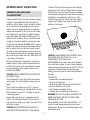
To reduce the risk of drowning from hair and body
entrapment, install suction fitting(s) with a marked
flow rate that is not less than the flow rate marked
on the remote packaged unit.(note: these are factory
installed). Do not operate the tub with any of the
suction fitting covers off. These covers are there to
prevent hair or objects from being sucked into the
plumbing. See Figure 1.
IMPORTANT! READ AND FOLLOW
ALL INSTRUCTIONS.
A green colored terminal (or wire connector marked
"Ground") is provided within the control box. To
reduce the risk of electric shock, connect this terminal or connector to the grounding terminal of the
electric service or supply panel with a continuous
copper wire equivalent in size to the circuit conductors supplying this equipment. In addition bonding
lugs are provided and marked "Bonding Lugs". To
reduce the risk of electric shock, connect the bonding lugs in accordance with the local electric code.
At least two lugs marked "BONDING LUGS" are provided on the external surface of the supply terminal
box. To reduce the risk of electrical shock connect
the local common binding grid in the area of the hot
tub to these terminals with an insulated or bare copper conductor not smaller than No.6 AWG. (Note: this
is pre done at the factory)
Figure 1
CAUTION: THE EQUIPMENT AND CONTROLS SHALL
BE LOCATED NOT LESS THAN 3.5ft. / (1 m)
HORIZONTALLY FROM THE hot tub.
HYPERTHERMIA occurs when the internal temperature of the body reaches a level of several degrees
above normal body temperature of 98.6ºF (37ºC).The
symptoms of hyperthermia include drowsiness,
lethargy and an increase of internal temperature of
the body.
All field-installed metal components such as rails,
ladders, drains or other similar hardware within 10
ft. (3m) of the hot tub shall be bonded to the equipment grounding bus with copper conductors not
smaller than #6AWG.
CAUTION: WIRING CONNECTED IN THIS BOX MUST
BE RATED AT 600V.
THE EFFECTS:
• unawareness of impending hazard;
• failure to perceive heat;
• failure to recognize the need to exit the hot tub
• physical inability to exit hot tub
• fetal damage in pregnant women.
• Unconsciousness and danger of drowning.
Do not attempt to fix any thing within the management system. The high voltage can cause injury or
death.
The tub must be hooked up to a G.F.C.I. (ground
fault circuit interrupter) by a licensed electrician. Use
the test button on your G.F.C.I. monthly to ensure it
is working properly.
WARNING: THE USE OF ALCOHOL OR DRUGS CAN
GREATLY INCREASE THE RISK OF FATAL HYPERTHERMIA IN HOT TUBS.
Always make sure there is an adequate sanitizer
level in your tub before entering. Failure to do so
may cause skin irritations or illness. Use a test kit or
test strips to check.
Recommended time in water at 100ºF/38ºC is 15
minutes. Lower temperatures will permit longer
bathing times. Always check the temperature of the
water before entry.
CAUTION: WATER TEMPERATURE IN EXCESS OF
100ºF/38ºC MAY BE INJURIOUS TO YOUR HEALTH.
-1-
Warning: Any person with the following conditions
should consult their Physician before using a hot
tub. Diabetes, High blood pressure, Heart disease,
Circulatory problems, Pregnant women or those
taking medication prescribed by their Physician.
Do not allow electrical devices to such as portable
stereos, TVs, hair dryers within 5 feet/1.5 meters of
the tub. Failure to do so could result in death due to
electrocution should the device fall in the water.
Warning: Always provide adequate supervision when
children are using the hot tub
Always follow instructions on Chemicals closely.
• Add one at a time
• Measure accurately
• Add chemical to water not water to chemicals.
• Store chemicals in a cool dry place, do not allow
liquids to freeze.
• Do not mix products together.
BEACHCOMBER’S SAFETY FEATURES
Molded Interior Steps
Beachcomber hot tubs are made with checker plate
flooring designed to make entry and exit safer.
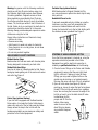
Molded Side Hand Grips
Found on all sides of a Beachcomber hot tub, these
hand grips make getting out of the seat much easier
and safer. See Figure 2.
Figure 2
Protec Step (optional feature)
If your hot tub is equipped with the Beachcomber
Protec option, it includes the Protec Safety step to
make entry and exit of the hot tub easier and safer.
Always secure the step to the hot tub with the
hardware provided to ensure maximum safety and
protection to the Protec Equipment.
Portable Step (optional feature)
With Beachcomber’s Original Portable Hot Tub,
you can purchase an optional two level step for easy
entry and exit.
Heatshield Cover Locks
To prevent unwanted entry by children or unauthorized users, use the cover lock assemblies that
come as a standard feature with each hot tub.
Screw the female half on to the hot tub skirting with
the stainless screws provided. See Figure 3.
Figure 3
STARTING UP A BEACHCOMBER HOT TUB
Once the Protec equipment is hooked up, using the
separate instructions provided in the Protec
Equipment box and the electrical connection is
made by a qualified electrician, do the following:
1. Check all union fittings on the Protec and Portable
equipment to ensure that they are tight. Hand
tight is sufficient. If leaking is noted at these
fittings you may need to tighten further or the
gasket may be missing or not seated properly.
Unscrew the union and check if this is suspected.
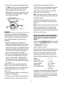
2. Open all knife valves (see Figure 4) that are
pointing up. Leave all valves that are facing down
closed. Fill the hot tub with water from a garden
hose. You can hang the hose over the edge of the
hot tub or hook it up to the black drain/fill valve
located down by the
pumps and fill from the
bottom. Allow some
water to run out of the
drain fitting to release
any potential stagnant
water.
Figure 4
-2-
3. Fill the hot tub to half way up the skimmer opening. Note: If your hot tub is Hush Pump equipped
your level can be lowered to one third up the
skimmer opening. This will allow for more
displacement if the hot tub is subjected to use by
more than the recommended amount of people
for that model. See Figure 5.
how many times a day the filter hours occur.
On 700 series, you can adjust temperature, amount
of hours the hot tub filters and a time clock that
needs to be set to your local time so the system
knows when to run the filter times.
Note: In the event of a power outage, the 300 and
500 series will default back to the factory filter and
temperature settings.
On 700 series the settings are backed up for 30
days and you will not have to reset once power is
back on.
Note: 700 series hot tubs with Hush Pump, the Hush
Pump will not resume 24 hour filtration until the
start of the next filter cycle. You can advance the
time clock 24 hrs if you do not want to wait until the
start of the next filter cycle.
Figure 5
WARNING!
Over filling will not allow room for displacement
from people entering the hot tub. Under filling could
cause an airlock in the system and could lead to
pump and heater damage not covered by your
guarantee.
4. Open the air bleed knobs to release any air
trapped in the external plumbing. There is one on
the 300 and 500 series hot tubs, two on a 500
series with Hush pump and a standard 700 series
and three on a 700 series with Hush pump. Once
all air is bled from the system, open any knife
valves that are facing down. See Figure 4.
5. Turn on your GFCI breaker. The circulation pump
will come on and the heater light or icon will
come on. If the fill water is colder than 50ºF /
10ºC, the pump(s) will go to high speed for 30
seconds, then back to low speed, then the heater
will come on.
Now that the hot tub is up and running and the
heater is on you need to check the settings and
possibly change them to suit your individual needs.
The default set temperature on all hot tubs is
100ºF / 37ºC.
On 300 series Digital systems, the only setting you
can adjust is the temperature.
On 500 series, you can adjust the temperature and
the amount of hours the hot tub filters, as well as
WATER CARE PRODUCT STARTUP PROCEDURE
Follow these basic steps before entering the
hot tub.
Add a full bottle of Eliminate #1. Wait one hour. Add
2 oz/60 ml of Eliminate Plus #2. Add 3.5 oz/100 ml
of Purezyme #3. Wait 6 hours.
Add your sanitizer of choice.
Please note: Beachcomber offers several water care
programs to suit your needs; ask your dealer for a
tote card for those specific details - your startup
regimen may vary slightly. Beachcomber recommends the following parameters for hot tub water:
pH Level
Sanitizer level
(chlorine or bromine)
Calcium Hardness
Total Alkalinity
Total Dissolved Solids
7.2 - 7.8
3 - 5 ppm
150 - 200 ppm
100 - 120
not more than
1500 ppm
Your dealer may recommend slightly different levels
depending on your local source water. Please see
your dealer for more information by taking a water
sample in to be analyzed, or, check our website at:
www.beachcomberhottubs.com
-3-
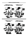
EQUIPMENT CONFIGURATION DIAGRAMS
-4-
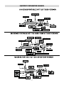
EQUIPMENT CONFIGURATION DIAGRAMS
-5-
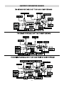
EQUIPMENT CONFIGURATION DIAGRAMS
-6-
EQUIPMENT CONFIGURATION DIAGRAMS
-7-
EQUIPMENT CONFIGURATION DIAGRAMS
-8-
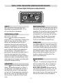
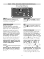
DIGITAL SYSTEMS, PROGRAMMING, OPERATION AND ERROR MESSAGES
300 Series Digital 1000 System including Model 160
PRESET FILTER CYCLES
Your hot tub is set to filter itself twice a day. The first
filter cycle will start one minute after the hot tub is
powered up. The second filter cycle will begin twelve
hours after the start of the first filter cycle. Filter
cycle duration is 2 or 6 hours long, and is set at the
time of delivery. During filtration, the low-speed
pump and ozone generator (if installed) will run.
Contact your local dealer to change the cycle.
START UP
When your hot tub is first powered up, it will
automatically heat and maintain 100°F / 37.5°C
until you change the set temperature.
TEMPERATURE ADJUSTMENT
(60°F-104°F) / (16°C-40°C)
Press the
pad to display the temperature
previously set. This set temperature is flashed on the
display. In a few seconds, the numbers will stop
flashing, and the display will show the actual
temperature. Pressing the pad a second time will
cause the set temperature to increase or decrease
depending on what direction was last chosen. Each
press to follow will change the set temperature in
the same direction. If the opposite direction is
desired release the pad and let the display revert to
the actual water temperature. Press the pad to
display the set temperature, and again to make the
temperature change in the desired direction. Actual
water temperature will reappear on the display after
changing the temperature setting.
STANDBY MODE
Press
then
within 3 seconds to prevent the
hot tub from operating at any time. "Sb" will appear
on the display. Standby mode should be used when
removing or replacing the filter. All hot tub functions
will be disabled except for freeze control. Press any
button to resume hot tub operation. Do not use
stand-by for draining and refilling; shut off the
power at your breaker panel.
DISPLAY MESSAGES
"OH"
"Overheat" - The hot tub has shut down. Either the
water has reached 112°F / 44°C, or the high limit
sensor has detected 118°F / 48°C at the heater.
DO NOT ENTER THE WATER. Remove the hot tub
cover and allow water to cool. At 110°F / 43°C, the
hot tub should automatically reset. If the hot tub
does not reset, then turn off all power to the hot tub
and contact your dealer or service organization.
LIGHT/MASSAGE
Press the
pad to cycle through the light and jets
features. The operating sequence is as follows: 1)
low-speed pump, 2) low-speed pump and light, 3)
high-speed pump and light, 4) high-speed pump
only, and 5) off. The low-speed pump automatically
turns off after 1 hour. The high-speed pump stops
after 15 minutes. The light turns off after 2 hours
of use.
-9-
"FL"
"Flow" (Flashing) – Flow of water is inhibited. Check
and open any closed knife valves. Check for correct
water level. Clean or replace your Microfilter.
"FL"
"Flow" (Not flashing) - Flow switch has malfunctioned. Contact your dealer or service organization.
"Sn"
"Sensor" - Hot tub is shut down. The high-limit or
water temperature sensor is not working. Contact
your dealer or service organization.
"Sb"
"Standby" - Hot tub is in standby mode. All hot tub
functions are disabled except for freeze control.
Press any panel button to resume operation.
Heat Light Flashing
"Summer Standby Mode" – Filtering has stopped:
water temperature is 3°F / 1.5°C or more above set
point after 3 hours of a filter cycle. If water cools to
1ºF / 0.5ºC above set temperature and the system is
still in filter mode, filtering will resume.
- 10 -
DIGITAL SYSTEMS, PROGRAMMING, OPERATION AND ERROR MESSAGES
500 Series Digital 2000 System
START UP
When your hot tub is first powered up, it will
automatically heat and maintain 100°F / 37.5°C
until you change the set temperature.
TURBO (OPTIONAL)
Press the
pad to turn the blower on and off. If
left running, the turbo automatically turns off after
15 minutes.
TEMPERATURE ADJUSTMENT
(60°F-104°F) / (16°C-40°C)
Press the
pad to display the temperature
previously set. This set temperature is flashed on the
display. In a few seconds, the numbers will stop
flashing, and the display will show the actual
temperature. Pressing the pad a second time will
cause the set temperature to increase or decrease
depending on what direction was last chosen. Each
press to follow will change the set temperature in
the same direction. If the opposite direction is
desired release the pad and let the display revert to
the actual water temperature. Press the pad to
display the set temperature, and again to make the
temperature change in the desired direction. Actual
water temperature will reappear on the display after
changing the temperature setting.
LIGHT
Press the
pad to turn the hot tub light on and
off. The light will automatically turn off after 2 hours
of use.
FILTER CYCLE PROGRAMMING
Due to the energy efficiency of the Hush Pump™,
your hot tub is set to automatically filter itself 24
hours a day. Although, there are other durations, it is
not necessary to change this setting. Filter duration
is programmable at the top-side panel. Press the
pad, then the
pad within 3 seconds and "FC"
will be displayed on the panel. ("FC" is the default
filter time and indicates a 12 hour cycle.) Continue
pressing the
pad to cycle through the rest of
the filter time options: "F2" - 2 hours, "F4" - 4
hours, "F6" - 6 hours, "F8" - 8 hours, "F0" - 10
hours, and FC for 12 hours. Press
once more to
select number of cycles per day. Press
for "C1"
- one cycle or "C2" – two cycles. Press
again to
exit programming mode. Note: If your hot tub is not
equipped with Hush pump™ then the factory default
setting is, F2-C2. Use the instructions above to
change if desired. The higher the bather load or
use frequency, the higher the filter setting needed.
MASSAGE
Press the
pad to activate the pump’s low speed,
again for the pump’s high speed, and once more to
turn off the pump. The pump’s low speed turns off
after 1 hour. The pump’s high speed turns off after
15 minutes.
- 11 -
During filtration the optional ozone generator (if
installed) will run. If Turbo equipped, the turbo will
come on for 30 seconds at the start of the first
filter cycle.
"Sb"
Standby" - Hot tub is in standby mode. All hot tub
functions are disabled except for freeze control.
Press any panel button to resume operation.
STANDBY MODE
Press
then
within 3 seconds to prevent the
hot tub from operating at any time. "Sb" will appear
on the display Standby mode should be used when
replacing the filter. All hot tub functions will be
disabled except for freeze control. Press any button
to resume hot tub operation.
Heat Light Flashing
"Summer Standby Mode" – Filtering has stopped:
water temperature is 3°F / 1.5°C or more above set
point after 3 hours of a filter cycle. If water cools off
to 1ºF / 0.5ºC above set point and the system is still
in filter mode, filtering will resume.
DISPLAY MESSAGES
"OH"
"Overheat" - The hot tub has shut down. Either the
water has reached 112°F / 44°C, or the high limit
sensor has detected 118°F / 48°C at the heater.
DO NOT ENTER THE WATER. Remove the hot tub
cover and allow water to cool. At 110°F / 43°C, the
hot tub should automatically reset. If the hot tub
does not reset, then turn off all power to the hot tub
and contact your dealer or service organization.
"FL"
"Flow" (Flashing) – Flow of water is inhibited. Check
and open any closed knife valves. Check for correct
water level. Clean or replace your Microfilter.
"FL"
"Flow" (Not flashing) – Flow switch has malfunctioned. Contact your dealer or service organization.
"Sn"
"Sensor" - Hot tub is shut down. The high-limit or
water temperature sensor is not working. Contact
your dealer or service organization.
- 12 -
DIGITAL SYSTEMS, PROGRAMMING, OPERATION AND ERROR MESSAGES
700 Series Digital 3000 System
to disable the heater. Press
, to see "SET STOP
FILTER 1" and adjust the time with
or
as
done above. Press
to see "SET START FILTER 2"
and proceed as above. Pressing
will enter the
new filter cycle times into the system and display
the current water temperature. At the start of each
cycle, the turbo (if installed) will turn on for 30
seconds to clean out the air channel.
The ozone generator (if installed) will run for the
duration of the filter cycle. Note: if your hot tub is not
equipped with the Hush Pump the default filter
cycles will be 2:00 am to 4:00am for filter cycle one
and 2:00 pm to 4:00 pm. You may need to add time
to these cycles if bather load is high or frequent to
maintain water clarity.
START UP
When your hot tub is first powered up, it begins
running in standard mode. Standard mode will
automatically heat and maintain 100°F / 37.5°C
until you change the set temperature. Pressing
the
pad switches the hot tub to economy mode,
which is not recommended with a hush pump™ as
this circulation pump draws very little current and
is designed to operate 24 hours a day.
TIME
To set the time, press , then
. You will see the
words "SET TIME" flashing on the display Pressing
or
once will begin changing the time in
one-minute increments. Press either pad to stop the
time from changing. TO scroll the time quickly,
briefly hold down either the
or
button and
then release. The time will change rapidly. Hit either
button to stop. Press
to enter the correct time
into the system.
TEMPERATURE ADJUSTMENT
(60°F-104°F) / (15°C-40°C)
Press either
or
once to display the last
temperature that was set. If either pad is pressed
within 3 seconds, the temperature setting will
increase or decrease in 1oF increments. Actual
water temperature will reappear on the display after
changing the temperature setting.
FILTER CYCLE PROGRAMMING
Due to the energy efficiency of the Hush Pump™
option, your hot tub is set to automatically filter itself
24 hours a day. Although there are other filter
durations, it is generally not necessary to change
this setting. Filter duration is programmable at the
topside panel. Press ,
,
within 3 seconds.
"SET START FILTER 1" will appear on the display.
Press
or
to change filter 1 start time. When
"SET HEAT" is on the display, press
"on" to
warm the water during filtering, or press
"off"
MASSAGE 1
Press the 1 pad once to activate the pump1’s low
speed, again for the pump’s high speed, and once
more to turn off the pump. The pump’s low speed
turns off after 1 hour. The pump’s high speed turns
off after 15 minutes of use.
- 13 -
For hot tubs with turbo option:
Press
,
,
, then the
pad within 3
seconds to lock. To unlock, press the ,
,
pads within 2 seconds.
MASSAGE 2
Press the 2 pad once to activate the pump2’s low
speed, again for the pump’s high speed, and once
more to turn off the pump. The pump’s low speed
turns off after 1 hour. The pump’s high speed turns
off after 15 minutes of use.
STANDBY MODE
Press
or
then
within 3 seconds, to
prevent the hot tub from operating at any time.
Standby mode should be used when replacing the
filter. All hot tub functions will be disabled except
for freeze control. Press any button to resume hot
tub operation.
TURBO (OPTIONAL)
Press the
pad to cycle through the highest to
lowest setting, then to turn off the turbo. If left
running, the turbo automatically turns off after 15
minutes.
DISPLAY MESSAGES
TIME AND TEMPERATURE INVERSION
Press
or
, then
1 within 3 seconds to
invert the time and temperature display. Press the
same sequence to set back.
"OH"
"Overheat" - The hot tub has shut down. Either the
water has reached 112°F / 44°C, or the high limit
sensor has detected 118°F / 48°C at the heater.
DO NOT ENTER THE WATER! Remove the hot tub
cover and allow water to cool. At 110°F / 43°C, the
hot tub should automatically reset. If the hot tub
does not reset, then turn off all power to the hot tub
and contact your dealer or service organization.
PANEL LOCK
Press the pad, the empty space between "warm"
and "light" pads, then the
pad within 3 seconds.
When locked, the display will show the temperature
you have chosen along with the "lock" symbol. To
unlock, press the
pad, then the space between
"warm" and "light" pads, then the
pad within
2 seconds.
The lock symbol will disappear and all panel pads
will work again.
For hot tubs with turbo option:
Press
,
,
within 3 seconds.
To unlock, press the
,
,
pads within
2 seconds.
"FLO"
"Flow" (Flashing) – Flow of water is inhibited. Check
and open flow valves. Check for correct water level.
Clean or replace your Microfilter.
"FLO"
"Flow" (Not flashing) - A pressure switch has
malfunctioned. Contact your dealer or service
organization.
TEMPERATURE/FILTER CYCLE LOCK
Press
, then press the
, the empty space
between "warm" and "light" pads, then the
pad
within 3 seconds. The ,
, and
buttons are
now locked. The display will show the "lock" symbol
and "set heat". It will also display the temperature
you’ve chosen when the
or
is pressed. To
unlock, press the
pad, the empty space between
"warm and "light" pads, then the
pad within 2
seconds. The lock symbol will disappear and all
panel pads will work again.
"COOL"
"Cool" – Water temperature is more than 20°F / 7°C
below the temperature you last set. No action
required. Hot tub is functioning properly.
"ICE"
"Ice" – Potential freeze condition is detected. No
action required. Pump(s) will automatically activate
regardless of hot tub’s status.
- 14 -
"Sn1"
"Sensor1" - Hot tub is shut down. The high-limit
sensor is not working. Contact your dealer or
service organization.
"Sn3"
"Sensor3" - Hot tub is shut down. The water
temperature sensor is not working. Contact your
dealer or service organization.
"Stby"
"Standby" - Hot tub is in standby mode. All hot tub
functions are disabled except for freeze control.
Press any panel button to resume operation.
Heat Light Flashing
"Summer Standby Mode" – Filtering has stopped:
water temperature is 3°F / 1.5°C or more above set
point after 3 hours of a filter cycle. If water cools off
to 1º F / 0.5º C above set point and the system is
still in filter mode, filtering will resume.
- 15 -
MODEL 320M AND 320 XM
MECHANICAL SYSTEMS
These are non digital systems which use a
mechanical equipment pak.
If you have the 110 volt version the heater will not
work when you have the pump on high speed due to
the amperage capacity of the 110 volt circuit in your
house. With the 240 volt version, the heater will
operate when the pump is turned to high speed.
High–Limit Reset
This is a safety device that will shut the system
down if a water temperature above 110ºF is sensed
at the heater housing. A return knife valve on the
left side of the pak left closed would cause the
water to overheat and kick out the high-limit switch.
Manually reset this button after approximately
1 hour. It is a red button that sticks out of the front
of the white pak box.
Start up / Temperature Setting
Remove the equipment door from the hot tub and
open the two knife valves. See Figure 4. Locate the
air bleed knob and open to bleed any air out of the
system then turn the on/off switch to on. Make sure
all jets are in the open position. Once all air is bled
out of the system, and good flow is felt from the jets
you can turn on the heater. The temperature adjustment is done down at the equipment.
Activation Buttons
There are two push buttons located up on the top
of the hot tub. One button is to turn your pump from
low speed circulation to high speed jet operation.
The other is to turn the light on or off. Don’t forget to
turn the light off after each hot tub use. Failure to do
so can reduce the life expectancy of the light bulb.
Air Control Valves
There is one air control lever between the activation
buttons. Turn the lever to the two o’clock position to
allow warm air to be drawn into the jets from the
equipment area. See Figure 6.
Turn the thermostat knob up to maximum setting;
put a Beachcomber or a good quality, accurate
floating thermometer in the water. Once the temperature on the thermometer is up to your desired
temperature, turn the dial backwards slowly, just
until the heater on indicator light goes out. This will
then keep the water at your desired temperature.
Note: There is a 2ºF variance above or below your
desired temperature with mechanical thermostats.
Activating the pump to high speed will draw more
air. Turn the lever back to the 6 o’clock position to
stop the air from being drawn in. This is the
recommended position when not using the hot tub.
Continuous / Economy Switch
If the economy setting is used the pump will only
run when the thermostat senses a demand for heat.
During warm summer months when the demand for
heat is low, you may not get enough circulation time
to maintain water clarity.
If you select continuous mode, the pump will run 24
hours a day and the heater will turn on and off from
the sensing of the thermostat. In extremely warm
weather you may need to remove the equipment
door to provide extra ventilation to the pump. Failure
to do so may cause the pump to overheat and shut
off or heat the water to an unsafe temperature.
Figure 6
- 16 -
refilling. Use test strips to check or have your
dealer perform the test. The ideal range is
100-120 ppm.
WATER CARE AND MAINTENANCE
Now that you are familiar with the operation of your
Beachcomber hot tub you need to become familiar
with the care and maintenance of it.
4. Calcium Hardness. Too high a level can cause
cloudy water or scaling on the hot tub surface and
heating element. Too low a level can lead to
excess foaming in the water. Use Protect to
increase the level, use fresh water to lower the
level. Adjust at initial fill and when refilling. Your
dealer must check this for you. The ideal range is
150 – 200 ppm.
Water Care and Chemistry
This is a very important component to protect your
hot tub and its equipment. Failure to maintain proper
water balance could damage your hot tub and
equipment. See your guarantee for details. Your
dealer should be able to provide you with free water
analysis and information. Also see Beachcomber’s
Guide to Hot Tub Water Care for additional
information.
5. Other important additives
a) Metal sequestering product. This must be
added to keep any metals in the water in
solution form. Use Eliminate #1 at initial fill.
1. Sanitizer level. Always maintain an adequate
sanitizer level. Failure to do so will result in cloudy
water, odor and skin or respiratory problems. The
ideal range is 3 - 5 ppm.
Check daily with test strips or drops. See your
local Beachcomber Dealer to find the right system
for you.
b) Scale inhibitor. This is to protect surfaces in
the hot tub from calcium buildup forming on
them. Use Eliminate Plus #2 at initial fill and
weekly.
c) Clarifier. This product agglomerates tiny
particles in the water making them easier to
be picked up by the filter. It also provides
lubrication to seals. Use Pure Blue at initial fill
and weekly.
WARNING!
Always leave the cover open for one hour when
shock treating the water. The high levels of sanitizer
can damage the underside of your cover. This is not
covered by your guarantee.
d) Enzymes. These are a natural compound
designed to eliminate scum and organic
contaminants. Use Purezyme at initial fill and
weekly.
2. pH Level. This determines the acidity or alkalinity
of your water, 7.0 being neutral. Water that is too
acidic will damage the metal parts of your hot
tub, water too alkaline will cause cloudiness, scaling and eye irritation. Check weekly with test
strips or drops. The ideal range for hot tubs is 7.2
to 7.8. Use pH Plus or Minus to adjust.
The water in your hot tub needs to be changed three
to four times a year or more if bather load is high. To
calculate the change frequency, use the following
formulas.
# Days = 1/3 (Volume in US Gallons)
3. Total alkalinity. This must be balanced to stabilize your pH level, prevent scaling and ensure your
sanitizer works at peak efficiency. Use Resist to
increase the level. Adjust at initial fill and when
Max # of daily bathers
- 17 -
Heatshield and Step Tops
HOT TUB CARE AND MAINTENANCE
As with any vinyl product that is exposed to the
weather, the better the care, the longer it will last.
Use a mild dish soap solution to remove dirt on the
cover and then treat the vinyl with Cover All. Avoid
application in the hot sun. Note: While the
Heatshield is strong enough to withstand up to 2
feet of snow it is not designed to support the weight
of children or pets walking on it or adults sitting
on it. This will break the foam inners and lead to
premature failure of the cover.
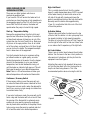
Filter Removal and Maintenance
The 25 sq ft. Microfilter in the hot tub should be
cleaned approximately every two weeks or more if
bather load is high. Failure to clean the filter can
result in cloudy water, odor and potential equipment
damage due to decreased flow.
To remove the filter, put the hot tub on stand-by (see
digital operation instructions for your model).
Stand-by prevents debris from the filter or objects
in the water from being sucked into the pump.
Note: The hot tub will stay in stand-by until either
the external freeze sensor detects 50ºF / 10ºC or the
temperature sensor senses a temperature more than
20ºF / 6ºC below set point.
Hot tub Cabinetry and Steps
If your hot tub has natural cedar and you want to
keep it looking new, use Nu Wood Stain Clear once
a year.
To remove, twist the trim ring to unlock it and
remove with the floating weir assembly, then lift out
the basket and then pull out the filter. Remove any
hair or debris from the basket.
If the cedar is weathered some, use Nu Wood
Natural or Twilight to bring back the color. Sanding
with 100 grit may be necessary if weathering is
advanced. If the cabinet is Enviroskirt™ simply
clean with a mild dish soap solution from time to
time.
Soak the filter in a cleaner such as Filter Pure
overnight and then remove and rinse thoroughly
with a hose spray nozzle to remove cleaner residue.
It is recommended that you alternate filter cleaning
each month with Filter Cure. It is also advisable to
have two filters, install the spare filter while the
other is soaking in the cleaner.
Plastic Components
Cleaning of the Acrylic Surface
The jets should be removed periodically and rinsed
out to remove debris from the spinning assemblies.
If calcium build-up is present, soak the parts in
Filter Cure to loosen the calcium and then scrub
with a brush and hose off.
The acrylic surface is very easy to maintain and care
for. Use Tub Clean to remove water level scum lines
and some warm water and a damp cloth to wipe
down the rest of the surface.
If a lot of hair and debris is present on suction
covers located in the foot well, this can reduce
water flow to the pumps. Manually remove when
the hot tub is empty or full.
Never use a cleaner that contains ammonia. This
could damage your acrylic surface. Avoid leaving the
hot tub empty and the Acrylic exposed to hot sun.
Always put the Heatshield back on the hot tub.
- 18 -
or the seat jets on the left of the hot tub if the water
flow is diverted to them.
On all models more air is drawn in when the jet
pump is on high speed than when the pump is on
low speed.
Air Control Valves
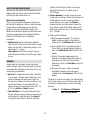
OPERATION OF HOT TUB INTERIOR FEATURES
Massage Inserts, or “Jets”
The jets in a Beachcomber hot tub are known as
Energ-Jets™1-small, 2-medium and 3-large. They
are interchangeable within the same sizes. Simply
turn them counterclockwise until they click and pop
out. To re-install, line up the small protrusion on the
back of the face plate with the slot on the white
water port and then turn clockwise and push in until
they click in. The jets can also be individually turned
off/on. Simply turn clockwise to turn off the water
flow and counterclockwise to turn on water flow.
Neck jets on model 350 pull out to turn on, push
back in to turn off. To turn on the neck jet on 500
and 700 series hot tubs turn counterclockwise to
turn on and clockwise to turn off. If this jet does not
turn off then carefully pry the face plate off with a
flat head screw driver and then screw the internal
portion back in by hand. Then pop the face plate
back on and turn it clockwise to tighten in the
internal portion.
Figure 7
RFM Diverter Valve (optional feature)
The purpose of this valve is to divert water flow
between either the RFM foot jets or the seat jets. On
700 series hot tubs it diverts water flow from massage 2 pump between the RFM foot jets or the seat
jets on the left side of the hot tub. See Figure 8.
Always turn the pump to low speed or off before
attempting to turn the valve handle. Failure to do
this could cause the handle to break due to the high
velocity of water moving through the valve. We recommend that when the hot tub is not being used
that the handle be left in the center position. This
ensures that water in both zones is always turned
over during periods of non use.
Air Control Valves
There are two air control valves located on either
side of the touch pad. See Figure 7. In the six
o’clock position they are off, meaning no air can be
drawn to the jets. To allow air to be drawn in, turn
the lever to the 2 o’clock position. On 300, and 500
series hot tubs the left air control services the seat
jets on the left of the hot tub and jets in the foot
well. The right air control services seat jets on the
right side of the hot tub. On the 350 model and 500
series hot tubs with the RFM (Reflex Foot Massage)
option, the left air control services the RFM jets
when the water flow is diverted to them and the
right air control services all the seat jets. On 700
series the left air control services seat jets on the
right side of the hot tub, the right air control services
foot jets and the remainder of the seat jets on the
left side of the hot tub. On 700 series hot tubs with
the RFM option, the right air control will service the
RFM jets in the foot well if water is diverted to them
Figure 8
Hot Tub Light
All Beachcomber hot tubs come with a standard 11
watt, 12 volt incandescent under water light. On 700
series hot tubs the light output is variable from high
to medium to low.
- 19 -
To replace a burned out bulb, turn off the power,
drain the hot tub, and unscrew the lens with the
wrench provided with your hot tub. Carefully pull out
the burned out bulb and then replace with a new
one. Screw the lens back in until tight. Do not over
tighten!
If the hot tub has the optional Everlite™ then, when
turned on it will cycle between the three colors, turn
off and on within 5 seconds and it will stop at one of
the colors. Continue turning off then on two pick one
of the other two colors. If left off for more than 10
seconds it will go back to cycling when turned on.
Ozone Generator (optional feature)
Installation of an ozone generator will reduce the
demand on your primary sanitizer which in turn will
reduce the frequency of sanitizer addition. It does
not replace your sanitizer. The ozone generator is a
black box mounted on the back wall of the equipment area. It has a clear viewing window on the
right end. This window will show a purple glow from
the micro chip, when the ozone generator is on
during programmed filtering times. The purple glow
(best seen at night) is what produces the ozone gas.
Over time the purple glow will start to diminish to
the point no ozone is being produced. The output is
rated at 9000 hours. If your hot tub is in a programmed filter cycle time, not to be confused with a
heat demand cycle and no purple glow can be seen
you may need to replace the micro chip.
To replace the chip, turn off the breaker, unplug the
unit from the management system, disconnect the
braided line, remove the two screws holding it on
the equipment wall and turn over and remove the
three screws holding the back cover on. Unplug the
three wire connections and then install the new chip
in reverse order. New chips are available from your
local dealer. See Figure 9.
ACSS, (optional feature)
550x, 578 & 580 Model & 700 Series
AquaCoustic Surround Sound System™
This system is designed for lower level easy listening and not high volume levels which may disturb
neighbors.
The remote control is water resistant so if dropped
in the water momentarily it will not damage it. It is
not designed to be left in the water. Use the
remote storage shelf found at the top of the console
to store the remote when not in use. The remote will
not work from inside the hot tub if the console door
is open. The small plastic emitter affixed to the door
glass is the reason; it must be lined up with eye on
the deck for the remote to work from inside the hot
tub. Please refer to the CD player manual for further
information about the model CD player in your hot
tub. See remote control user instructions for detailed
operations.
view window
Figure 9
Hush Pump
The Hush pump is a very quiet, low amperage high
flow circulation pump that looks after the filter and
heating functions of your hot tub. It comes set from
the factory to operate 24 hours a day. This is the
recommended run time due to the energy efficiency
of it. If you desire less than 24 hour operation you
can reprogram it on your control panel. Be sure not
to decrease the run time to the point that you are
not getting enough hours of filtration a day to
maintain water clarity.
Turbo (optional feature) 500 & 700 Series
The purpose of the turbo option is to increase the
amount of air that comes out of the jets. The benefit
is a slight increase in the feel of the jet pressure. On
700 series hot tubs the turbo has 3 speeds and on
500 series it only has a single speed. If the turbo is
activated and the air controls are closed, the air
from the turbo will come out of the 4 salt shaker
relief jets found in the foot well of the hot tub.
- 20 -
4. Lock your cover on the hot tub to maintain a safe
environment for pets or children. If in a high wind
area install Hurricane straps available from your
local Beachcomber dealer.
Upon returning do the following:
1. Check pH and sanitizer level and adjust if
necessary.
DRAINING A BEACHCOMBER HOT TUB
Before draining, check the sanitizer level; it should
not be above 1.0 to ensure no harm is done to the
surrounding environment. Turn the power off at the
breaker.
To drain the hot tub, remove the safety cap from the
fitting threaded into the black drain/fill valve found in
behind the door on a Portable version or under the
step on the Protec version. See Figure 10.
If leaving for 5-14 days and no one can come by
to maintain the hot tub do the following:
1. Lower the temperature to around 80ºF. Sanitizers
last longer in cooler water.
2. Check and adjust pH level if necessary.
3. Use either a Beachcomber floating tablet dispenser or a Holiday Tender tablet dispenser to
automatically dispense bromine or chlorine in
your hot tub. Use a low setting on these devices
as the demand for disinfectant will be low during
this time.
4. Lock the cover and attach a Hurricane strap in
high wind areas.
Upon returning do the following:
1. Check pH and sanitizer level and adjust if
necessary.
2. Return temperature setting to your desired level.
Figure 10
Attach the female end of your hose and place the
other end of your hose at a level lower than the
drain/fill valve to ensure complete draining. Turn the
outer part of the drain/fill valve counter clockwise
to open. As the level falls below the seats use your
hands to scoop water out of the seat contours
into the foot well. Draining will take approximately
2 hours.
Once the hot tub is drained then disconnect the
hose and close the drain valve if you are not going
to fill the hot tub through the drain/fill valve. If you
want to fill through this fitting, unscrew the threaded
adapter and thread in the male end of your hose and
then attach the female end to your tap and then
refill. Be sure to clean your hot tub surface before
refilling.
WINTER OPERATION INFORMATION
All Beachcomber digital hot tubs have a built in
freeze protection sensor. It is located on the bottom
of the heater housing (the stainless steel tube
attached to the bottom of the management system).
If a temperature of 50ºF / 10ºC is detected at this
sensor, the pump(s) high speed will activate for 30
seconds to draw warm water out of the hot tub. If
the hot tub is Hush Pump equipped, the sensor will
not be exposed to the freeze level as the water is
circulating 24 hours a day unless the hot tub is put
on stand-by and circulation is suspended. The
sensor will then override the stand-by mode if a
potential freeze condition is detected. The jet
pump(s) are also protected from freezing via the
small braided rinse line that runs from the front of
VACATION INSTRUCTIONS
If leaving your hot tub full and running while on
vacation for 3-5 days do the following:
1. Check and adjust pH level if necessary.
2. Shock-treat the water to raise sanitizer level.
Leave the hot tub cover half open for 1 hour.
3. Lower water temperature to minimum setting
(optional).
- 21 -
one pump to the front of the other pumps. There is
also a 1 minute, low speed purge cycle that happens
at the start of each filter cycle. Note: If refilling your
hot tub during winter, most source water is colder
than 50ºF / 10ºC. This means your freeze
protection will activate as soon as the system is
turned on. On 700 Series hot tubs, we recommend
that you do not use the economy setting during
freezing weather.
Winter Precautions
If your equipment is not working during freezing
temperatures you should first try to contact your
local Beachcomber dealer. Some stores have an
emergency number for winter. If you cannot contact
your dealer, call Beachcomber Customer Care at
1-800-663-6557 for instructions.
To prevent damage caused by the equipment
freezing, you can put a small space heater or trouble
light down by the equipment. Position the heater or
light so that it does not melt or burn anything. You
can also block off the step or door vent to keep in
the heat but it must be removed once the freezing
weather is no longer present.
In the event of a prolonged power outage, you need
to close the knife valves to keep the hot water in the
hot tub and then remove the drain plugs on the front
of the pumps to drain all the water from the external
plumbing lines and the pumps.
Removing these allows the last bit of water in the
bottom half of the pump to drain out.
4. Remove the filter element and store dry.
5. Lock cover and attach Hurricane strapping if in
high wind areas.
DOS AND DON’TS
Do’s
1. Read this manual thoroughly and follow the safety
guidelines provided at the beginning of this
manual.
2. Call your local dealer first if you have questions
not covered in this manual.
3. Follow water care instructions and guidelines.
Failure to do so can result in damage or problems
to the hot tub or the equipment.
4. Always leave your cover open half way when
shocking your water. If small children are present,
monitor the hot tub during this time to prevent
entry.
5. Test your GFCI circuit protector at least once a
month to ensure it is working correctly.
6. Rinse your filter at least once a week if the hot
tub is used daily.
Don’ts
1. Don’t enter your hot tub if the sanitizer level is not
adequate. This can cause respiratory and skin
problems.
2. Don’t walk on, sit on or put heavy weight on the
hot tub cover. This can cause the foam insert to
break.
3. Don’t leave the hot tub exposed to the sun if
empty. Always cover the hot tub with your cover.
4. Don’t allow use of the hot tub by children without
proper supervision.
5. Don’t attempt to repair electrical problems.
Consult your Beachcomber dealer.
6. Don’t attempt to drain and refill your hot tub
during freezing temperatures. The pump(s) wet
ends can freeze up during draining.
7. Don’t use glassware in or around your hot tub.
SHUT DOWN PROCEDURES
Beachcomber encourages the use of your hot tub
year round but if you prefer not to use your hot tub
for periods longer than 14 days you need to do a
proper shut down. Do the following:
1. Drain the hot tub as per instructions in the draining procedure.
2. Unscrew all union nuts on the front of the pump(s)
to allow any water in the external lines to drain
out. Don’t lose the gaskets found at these
locations.
3. Locate and remove the small black slotted drain
plugs found on the front of the pump(s) below the
union nuts that you unscrewed in step 2.
- 22 -
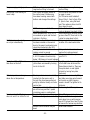
HOT TUB OPERATION TROUBLESHOOTING GUIDE
Problem Symptom
Control panel display is
alternating between FL or FLO
and the water temperature.
The pump is running.
Most Likely Cause
Filter is dirty
Knife valve is closed.
On non Hush tubs, jets that
receive flow from circulation
pump are closed
Low water level or water refill
causing an airlock in the system.
Control panel display is
alternating between FL or FLO
and the pump is not running.
Debris has built up in the Hush
pump impellor caused by continual
removal of the filter with out putting
tub on standby.
Pump cord is unplugged from the
management system.
Blown pump circuit fuse inside
management system
Pump has failed or frozen, not
creating flow.
Control panel display is
showing a constant FL or FLO,
tub is not working and none
of the buttons work.
Control panel display is
showing a Sn, Sn 1 or Sn3, and
the tub is not working and none
of the buttons work.
GFCI breaker is on but the
control panel is blank.
Pump is surging on high speed.
Flow switch has malfunctioned.
Temperature or High limit/freeze
sensor is not registering.
System fuse(s) are blown
Water level is too low on non
Hush tub.
Plug in center of filter basket is
not in place on non Hush tub.
- 23 -
Solution
Put hot tub on Standby, remove
filter and clean or replace.
Ensure all knife valves are in the
open or up position.
Turn jets counterclockwise to open.
Fill water to half way up the
skimmer opening; locate air bleed
knobs and open partially to release
air in piping.
Call your dealer for service or shut
down the system, close all knife
valves and remove face plate from
Hush pump to remove debris.
Plug pump cord back in.
Call your dealer for service.
If able to use an ohmmeter, turn
off power remove fuse and check
for continuity.
If freezing suspected, place trouble
light or space heater around
equipment to thaw out pump and
external piping and call your dealer
for service.
Call your dealer for service.
If tub is a 300 or 500 series, try
turning the power off then back on.
If this does not work call your
dealer for service.
Call your dealer for service. If able
to use an ohmmeter, turn off power,
remove fuses and test for continuity.
Raise water level in tub to at least
half way up the skimmer opening.
Install plug in basket, insert from
top of basket.
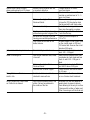
Pump is surging on high speed.
Hush pump is not running 24
hours a day.
G.F.C.I. breaker will not stay
on or trips intermittently.
Neck jet on 500 or 700 series
tubs does not shut off.
Water temperature is always
above the set temperature.
Remote control for CD player
does not work from inside the tub.
RFM jet nozzles are pointed toward
large suction fitting in foot well.
Filter cycles have been altered at
the control panel. Children may
have been messing around with
buttons and changed the settings.
If 700 series, power to the tub
has been interrupted.
Water temperature is 3ºF/1.5ºC or
more above set point and the heat
indicator is flashing.
If tub is new; the load neutral wire
has been inserted on the neutral
buss in the panel. Load neutral wire
should be inserted into the GFCI.
Heating element is defective and
leaking current to ground.
G.F.C.I. is worn out or defective. Class
A, G.F.C.I breakers should not trip
below 5 Milliamps of current leakage.
Internal portion of two piece neck
jet has been unscrewed by turning
too far to the left.
The temperature sensor is not fully
inserted into the sensor well in
the tub. May have been pulled out
partly by mistake. Usually on Protec
version tubs.
During hot weather the filter cycles
are set too long and the 2 speed
circulation pump is creating heat.
Door for CD player console is open
Emitter on door glass has come off.
Remote control batteries may be
dead.
- 24 -
Redirect nozzles away from large
suction fitting.
On 500 series turn power off then
on again to reset.
On 700 series reset to default
times, Filter 1- 2am to 2pm, Filter
2- 2pm to 2am, using the touch
pad. Then advance time clock 24
hour ahead to reset.
Wait until the start of the next filter
cycle or advance time clock 24 hrs.
When lowering the set point do not
go more than 2ºF, then wait for the
water to come down to that.
Call your electrician to change
location of the load neutral wire.
Call your dealer for service to
replace the heating element.
Call your electrician to replace
your G.F.C.I.
Carefully pry the faceplate off with
a flat head screw driver and the
thread internal back in. Then pop
face plate back on and tighten
internal by turning face plate
clockwise.
Loosen nut on senior entry fitting
and slide round grey wire forward
until metal on plastic tapping
sound is heard. The tighten nut to
hold wire.
Reduce length of filter cycles.
Close CD player console door.
Re glue emitter to door glass with
crazy glue. Line up with receiver
eye on CD player face. See CD player manual for receiver eye location.
Install new batteries.
Remote control does not work
when pointing directly at CD player.
The water is cloudy.
pH level is hard to keep balanced.
Water is foaming a lot.
Strong Chlorine or Bromine
smell in tub.
Acrylic surface has a white haze
on it after tub is drained.
Remote control batteries are low,
or remote is defective.
Sanitizer level is to low.
Change batteries or contact
your local dealer.
Shock-treat the water and then
maintain a sanitizer level of 3 – 5
ppm at all times.
Water is old or high in Total
Take a water sample to your dealer
Dissolved Solids.
to have the TDS checked or drain
the tub and refill with fresh water.
Filter element is dirty.
Soak filter in cleaning solution and
then rinse thoroughly or replace.
Plug from center of basket is not in Locate plug and install in basket
place allowing water to bypass filter. hole from the top.
pH balance is too high or too low
Check pH level and adjust to
causing poor sanitizer performance. 7.2 to 7.8.
Filter cycles are too low for the
Increase length of filter cycles. Done
bather volume.
on the control panel on 500 and
700 series tubs. Done on the circuit
board on 300 series.
Total alkalinity is not balanced.
Increase total alkalinity to correct
level. 100 – 120 ppm.
Low calcium hardness level, water
Raise calcium hardness level. See
is too soft.
your dealer to check level and how
much to add. 150 – 200 ppm is
ideal.
Water is old or high in Total
See your dealer to check TDS. Drain
Dissolved Solids.
and refill if above 1500 ppm.
Sanitizer level is below 3 ppm.
Check sanitizer level and increase
to 3-5 ppm.
Combined chlorines need to be
Shock water with either a chlorine
shocked to remove them.
or non chlorine shock treatment.
High calcium hardness level in the
water. Calcium has adhered to
the surface of the tub.
- 25 -
Eliminate Plus was not added on a
weekly basis to prevent calcium
from adhering to the acrylic surface.
Remove with solution of water and
Filter Cure using a soft bristle brush.
BEACHCOMBER HOT TUB CARE AND MAINTENANCE RECORD
Date
Hose off
filter element
Soak filter
element in
cleaning solution
- 26 -
Drain and
refill tub
Clean and
treat tub
cover
Re stain
cedar
cabinet
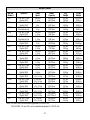
DETAILS CHART
Hot Tub
Model #
160
320
320M
320X
320XM
350
520
530
550C
550X
578
580
720
720RI
720X
730
740
750
System #
240 volt 5.5 kw
Digital 1000
120 volt 1.5 kw
Digital 1000
120 volt 1.5 kw
Mechanical pak
240 volt 5.5 kw
Digital 1000
240 volt 4 kw
Mechanical Pak
240 volt 5.5 kw
Digital 1000
240 volt 5.5 kw
Digital 2000
240 volt 5.5 kw
Digital 2000
240 volt 5.5 kw
Digital 2000
240 volt 5.5 kw
Digital 2000
240 volt 5.5 kw
Digital 2000
240 volt 5.5 kw
Digital 2000
240 volt 5.5 kw
Digital 3000
240 volt 5.5 kw
Digital 3000
240 volt 5.5 kw
Digital 3000
240 volt 5.5 kw
Digital 3000
240 volt 5.5 kw
Digital 3000
240 volt 5.5 kw
Digital 3000
Pump
Specs.
240 volt
1.5 hp
120 volt
1hp
120 volt
1 hp
240 volt
1.5 hp
240 volt
1.5 hp
240 volt
2 hp
240 volt
1.5 hp
240 volt
2.5 hp
240 volt
2.5 hp
240 volt
3.5 hp
240 volt`
4.5 hp
240 volt
4.5 hp
2-240 volt
1.5 x 2.5 hp
2-240 volt
2.5 x 3.5 hp
2 - 240 volt
1.5 x 3.5 hp
2 - 240 volt
2.5 x 3.5 hp
2 - 240 volt
3.5 x 3.5 hp
2 - 240 volt
3.5 x 4.5 hp
Water
Capacity
360 gallons
1363 litres
220 gallons
833 litres
220 gallons
833 litres
240 gallons
908 litres
240 gallons
908 litres
360 gallons
1363 litres
185 gallons
701 litres
264 gallons
1000 litres
360 gallons
1363 litres
360 gallons
1363 litres
360 gallons
1363 litres
400 gallons
1515 litres
350 gallons
1325 litres
350 gallons
1325 litres
350 gallons
1325 litres
398 gallons
1507 litres
398 gallons
1507 litres 3
398 gallons
1507 litres
Notes: 320 and 320M can be ordered upgraded to 220/240 volt.
320X, 320XM, 520 and 160 can be ordered downgraded to 110/120 volt.
- 27 -
Dry
Weight
650 lbs.
295 kg
425 lbs.
193 kg
425 lbs
193 kg
510 lbs.
232 kg
510 lbs.
232 kg
650 lbs.
295 kg
425 lbs.
193 kg
600 lbs.
273 kg
625 lbs
284 kg
650 lbs.
295 kg
650 lbs.
295 kg
725 lbs.
329 kg
675 lbs.
307 kg
675 lbs.
307 kg
675 lbs.
307 kg
800 lbs.
363 kg
800 lbs.
363 kg
800 lbs.
363 kg
Filled
Weight
3655 lbs.
1658 kg
2262 lbs.
1026 kg
2262 lbs.
1026 kg
2347 lbs.
1064 kg
2347 lbs.
1064 kg
3655 lbs.
1658 kgs
1971 lbs.
894 kg
2805 lbs.
1273 kg
3630 lbs.
1650 kg
3655 lbs.
1658 kg
3655 lbs.
1658 kg
4065 lbs.
1844 kg
3596 lbs.
1632 kg
3596 lbs.
1632 kg
3596 lbs.
1632 kg
4123 lbs.
1870 kg
4123 lbs.
1870 kg
4123 lbs.
1870 kg
Contact us:
Beachcomber Home Office
13245 Comber Way, Surrey, B.C. Canada V3W 5V8
North American Customer Care 1.800.663.6557
San Diego Beachcomber Worldwide Centre
1.866.250.7878
Fax line: 760.560.7882
Arnhem Beachcomber European Centre
31 (0) 26 327 4822
Fax line: 31 (0) 26 323 7836
Toronto Beachcomber Development Centre:
1.800.268.3966
Fax line: 905.829.2848
Laval Beachcomber Development Centre:
1.866.389.7878
Fax: 450.781.8722
www.beachcomberhottubs.com
04V0103