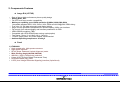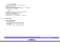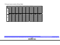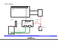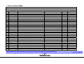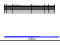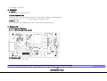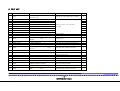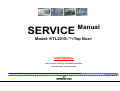
1
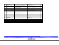
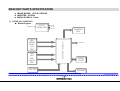
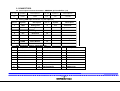
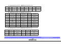
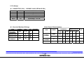
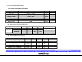
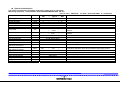
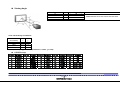
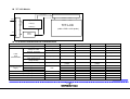
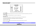
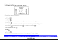
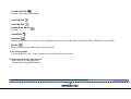
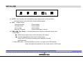
SERVICE Manual Model: KTL201S-**<Top Box> CONFIDENTIAL This Document is Property of KORTEK Corporation Note) KTL201S-** Patented by IGT 1 of 41 KORTEK R&D Center CONTENTS SAFETY NOTICE....................................................................................................................................................................................... 3 SPECIFICATIONS..................................................................................................................................................................……….......3~9 1. General Description 2. Components Features 3. Input Signal 4. Block Diagram 5. Service Parts (BOM) POWER SPECIFICATION………………………………………………………………………………………………………………………..10~14 1. Description 2. Electrical 3. Environment 4. Reliability 5. Mechanical 6. Part List Main Key parts Specification…………………………………………………………………………………………………….…….………15~27 1. LOTUS (10+31090003C) -Connectors, Schemetic… 2. Keypad(07+112209100) 3. INVERTER : FIF2064(10+410900006) 4. TFT-LCD : LTM201M1-L01 (54+320ASS000) How to set MENU ……………….…………………………………………………………………………………………….……..................28~30 1. OSD 2. How to select item(s) & set up level How to set Factory... ...............................................................................................................................…........................................31~33 KEY & LED...........................................................................................................................................................................................34~35 EDID Information...................................................................................................................................................................…................36 Analyze the Cause of Failure……… …………………………………………………………………………….………..….……………….37~40 1. Power Problem 2. Display Problem(No display / Display Noise) 3. Trouble Shooting Mechanical Dimension and Disassemble................................................................................................................................................41 2 of 41 KORTEK R&D Center SAFETY NOTICE WARNING: Only competent service personnel may carry out work involving the testing or repair of this equipment. This receiver must operate under AC 100-240 volts, 50/60Hz. Never connect to a DC supply of any other voltage or frequency. Potential high voltages are present when this receiver is operating. Operation of the receiver outside the cabinet or with the back cover removed involves a shock hazard from the receiver. Servicing should not be attempted by anyone who is not thoroughly familiar with the precautions necessary when working on high voltage equipment. Keep wires away from high voltage or high temperature component. When replacing a high wattage resistor (oxide metal film resistor) in circuit board, keep the resistor body 10mm away from the circuit board. Many electrical and mechanical parts in this equipment have special safety-related characteristics. Replacement parts which have such features are identified by designated symbol on the parts list. Before replacing any of these components, read the parts list carefully. If the fuse is blown, replace it with the fuse specified in the Parts List. SPECIFICATIONS 1. General Description The LOTUS is an advanced TFT LCD Monitor Control Board. This design enables a full conventional CRT monitor with a large size Active Matrix LCD module. It is suitable for video resolution up to UXGA @ 60Hz in all video modes, the full display area of the module is used. The design is implemented as a single printed circuit board. The LOTUS is designed to act as a full monitor. The LOTUS is designed to support various TFT LCDs under UXGA resolution by BIOS option, customers line-up their monitors with their own identity with following options. 3 of 41 KORTEK R&D Center 2. Components Features z Image B’d (LOTUS) • State of the art high performance picture quality design • Analog RGB , DVI • Full CRT multi-sync monitor compatibility • Multi-sync capability up to UXGA resolution @ 60Hz (1600x1200,60Hz) Compatible standard DOS, VGA, SVGA, XGA, SXGA and UXGA@60Hz VESA timing • True color (16.7M) data processing and display driving • Single control operated & transparent On-Screen-Display (OSD) user interface • Full control of all relevant display and interface parameters via OSD • VESA DDC2B compliant (TBD) • Compatible with VESA DPMS power saving modes(option) • Form factor: 78mm (L) x 110mm (W) x 13mm(H) • +12VDC single power: DC power adapter recommended. • Ambient Operating temperature: 0 to 40°C z Panel 1) LTM201M1 • High contrast ratio, high aperture structure • High speed response • SPVA (Super Patterned Vertical Alignment) mode • Wide Viewing Angle(L89,R89,U89,D89) • WSXGA+ (1680 x 1050 pixels) resolution • U-type 6 CCFTs(Cold Cathod Fluorescent Tube) • DE (Data Enable) only mode • LVDS (Low Voltage Differential Signaling) interface (2pixel/clock) 4 of 41 KORTEK R&D Center z Inverter (FIF2064) • • • • • Suitable Load : 20.1inch TFT LCD (6 U shape Lamp) Single Operate voltage 12V Backlight on/off and Dimming control Output current range : 3.0mA (min) ~5.0mA(max) / 7.0mA(typical) Operating frequency : 47~55KHz • • • • • z BLU Lamp Current : 4.0mA(min)~7.5mA(max)/7.0mA(typical) Lamp Voltage : 760Vrms(typical) Lamp Frequency : 40kHz(min)~60kHz(max) Operating Life Time : 50,000Hr(min) Startup Voltage : 0°C = 1,800Vrms, 25°C = 1,250Vrms 3. Input signal 1) Input signal Interface : ANALOG RGB(ADC) max 165MHz sampling rate support UXGA/60Hz analog R'B'G' known as SOG (Sync-on-Green) :DVI (TMDS) max 165MHz sampling rate support UXGA/60Hz 5 of 41 KORTEK R&D Center 2) Support Input resolution (Timing Table) IGT AVP WIDE 16X10 VIDEO TIMING MODES DESCRIPTION H V f KHz A uS B uS C uS D uS E uS POL F Hz O mS P mS Q mS R mS S mS POL 640X480 640X480 720X400 768X480 800X600 1280X1024 1440X900 1680X1050 37.880 63.938 55.935 65.290 37.50 31.469 31.649 29.820 POS 75.00 NEG 59.94 POS 70.087 NES 60.00 POS 60.310 POS 60.020 NEG 59.89 POS 59.95 POS NEG POS POS POS POS NEG POS 6 of 41 KORTEK R&D Center 4. Block Diagram Driver Board Panel Inverter LVDS_Dual +12V Panel Power +12V Inverter Power OSD Board +12V Image Board Power Image Board DVI VGA Power Adaptor(PS50) PC PC DVI Signal PC VGA Signal 7 of 41 KORTEK R&D Center 5. Service Parts (BOM) 01+512010100 PRODUCT,LCD,SET KTL201S-**(W/G)(RoHS) NO 1 2 3 4 5 6 7 8 9 10 11 12 13 14 15 16 17 18 19 20 21 22 23 24 25 26 27 28 29 30 CD_CHILD 07+112209100 09+590000001 10+210122013 10+220120003 10+31090003C 10+410900006 10+510303001 47+032210001 47+042210002 47+051910000 54+320ASS000 60+220100101 60+220100102 60+220100104 60+220100105 64+200010103 64+200010104 68+112103201 68+112403061 68+112403081 68+112404081 68+142004081 72+120004001 73+160000101 90+220010100 91+220010130 92+110011003 93+030000023 93+060000018 93+072010001 DC_ITEM_SPEC LOTUS(AD220), IGT(RoHS) TOUCH-25*15M(3n9469)(RoHS) 17-9320-206-01(RoHS) EXII-5710UC-02,IGT(RoHS) LOTUS(AD220)12V(RoHS) FIF2064-31B(RoHS) KT-PS50,12V,4/16A(RoHS) 6P/10P/6W,355mm(RoHS) 30P/30P/200mm(RoHS) 4P/4P/4W 350mm(RoHS) LTM201M1-L01-L(RoHS) FRONT 201 IGT(RoHS) BASE 201LCD IGT(RoHS) IVT COVER 201 IGT(RoHS) COVER 201 IGT(RoHS) D-SUB B/K(TRIMLINE)(RoHS) DVI B/K(TRIMLINE)(RoHS) PHW M3*20 천연(RoHS) PH*SW*PW M3*6 천연(RoHS) PH+SW+PW M3*8 천연(RoHS) PH+SW+PW M4*8 천연(RoHS) FH M4*8 천연(RoHS) M4 PI FN 천연(RoHS) SJCT-100 mm(RoHS) 530*191*408(I)-201LCD(RoHS) IGT 201LCD(RoHS) 1100*1100*120(RoHS) (600*600) RS-471 IGT(RoHS) 40W70L(RoHS) 2T*7*450 SPONGE(RoHS) NM_ITEM OSD MANUAL FOAM TAPE T/S 20.1" (CT3) CONTROLLER PCB AD B'D(WSXGA+) INVERTER AD ADAPTOR(20.1" LCD) CABLE INVERTER(AD220) CABLE LVDS(P6GND) CABLE ADAPTER TFT LCD 20.1" FRAME TFT LCD(67341400 A) FRAME TFT LCD(68586800 A) FRAME TFT LCD(54000400 A) FRAME TFT LCD(68867500 A) BRACKET BRACKET MACHINE BOLT MACHINE BOLT MACHINE BOLT MACHINE BOLT MACHINE BOLT NUT FLANGE CABLE TIE PACKING BOX CUSHION-P.E FOAM PALLET IGT 19UR(CRT) POLY BAG-HD EMI TAPE(AL TAPE) SPONGE TAPE 8 of 41 KORTEK R&D Center QT_REAL 1 0.009 1 1 1 1 1 1 1 1 1 1 1 1 1 1 1 2 4 13 4 1 10 2 1 1 0 1 1 2 DC_ITEM_UNIT PCS ROLL EA EA EA EA EA EA EA EA EA EA EA EA EA EA EA EA EA EA EA EA EA EA EA SET EA EA EA EA 31 32 33 34 35 36 37 38 39 40 93+072010002 93+081510001 93+1315A5006 93+220000002 96+120000056 96+140400101 96+140600151 96+140600352 96+141051051 96+320750701 2T*7*288 SPONGE(RoHS) 16500*6*1.6t VHB4956(RoHS) 20W15T100L (Panel 중앙) SILICA-GEL 20G(RoHS) ELECTRONIC(38*34)-IGT(RoHS) 40mm*10mm(RoHS) 60mm*15mm(RoHS) 60mm*35mm 무지(RoHS) 105mm*105mm BOX용(RoHS) TFT LCD MONITOR(75x70)-UL/TUV/CE(ROHS) SPONGE TAPE FOAM TAPE(양면) EMI GASKET(L) SILICAGEL LABEL(WARNING) BAR CODE LABEL BAR CODE LABEL BAR CODE LABEL BAR CODE LABEL LABEL PRODUCT-IGT 9 of 41 KORTEK R&D Center 2 0.15 2 1 1 5 1 2 1 1 EA ROLL EA EA EA EA EA EA EA EA POWER SPECIFICATION 1. Description This Product is AC to DC Power transfer device, it can provide for a 48W Single DC output With constant voltage source. 2. Electrical 2.1 Input Voltage (AC) a. From 100-240 V ac Nominal b. From 90-264 V ac Maximum 2.2 Input Frequency From 47-63Hz 2.3 Input Current a. 0.9 A MAX at 90Vac b. 0.5 A Max at 265Vac 2.4 Inrush Current a. 50A max at cold-start and 25℃, dc output full-loading and 115Vac input b. 80A max at cold-start and 25℃, dc output full-loading and 230Vac input 2.5 Hold-up Time 10msec minimum at dc output full loading and 115Vac 50/60 Hz 2.6 Input wattage at output no-load /100㎃ load condition a. Less than 5.0W at DC no load and 240Vac input Voltage and frequency a. Less than 5.0W at DC 200㎃ load and 240Vac input Voltage and Frequency condition 2.7 Efficiency 78% Minimum at dc output full loading and nominal AC input voltage range included dc output Cable voltage drop loss. 2.8 Safety Test a. Leakage current less than 0.195㎃ at 254Vac, 50Hz b. Hi-Pot Test : 1500Vac /60Hz for 1minute (Line /Neutral in common to the Monitor Chassis, No Break down 10 of 41 KORTEK R&D Center c. Insulation resistance: at dc 500Vdc, 1Sec between Primary to Secondary circuit, IR Shall ≥ 20㏁. d. Grounding test: AC 30A, 2Sec between input safety ground and SELV output GND, GR ≤ 0.1Ω . 2.9 Output Voltage and Current(DC) V out Range I out(min) I out(max) 12.0V 12.6-11.4V 0.2A 4.0A 2.10 Ripple and Noise Low frequency ripple (<100KHz) ≤ 300㎷p-p, tested by dc loading side parallel with a 10㎌/EC AND 0.1㎌/Ceramic. Capacitor and Measured Band Width with dc-20MHz 2.11 Over-Shoot and under-Shoot Less than of Nominal Voltage Value 2.12 Protection a. SCP: For short circuited protection and with auto-recovery function. b. OVP: Over-voltage protection with dc output voltage shutdown will be than less 18.0 Vac at full load c. OCP: Over – Current Protection, Range: 8.0A (max) on nominal AC input. 2.13 Turn on Delay time The output voltage should turn on from AC on to settle within regulation in less than 3.0 sec 2.14 Output voltage Temperature Coefficience Less than 0.2%/C 2.15 Output Transient Response Dynamic loading condition Dc output I1(A) I2(A) dVmax(V) Test-max dI /dT 12.0 0.00 2.0 +/1.0V 10msec ≥ 50mA/usec 12.0 2.2 3.5 +/1.0V 10msec ≥ 50mA/usec 3. Environment 3.1 Temperature a. Operation : 0 ~ 40℃ b. Storage: -10 to 70℃ 3.2 Humidity a. Operation: 20 to 80% 11 of 41 KORTEK R&D Center b. Storage: 10 to 90% 4. Reliability 4.1 MTBF 26280 Power On Hours at 25℃ 4.2 Temperature Rise Less than 45℃ at nominal AC input/ DC output full loading and environment Temperature 25 +/- 1 ℃ on Top /Bottom of plastic case. 4.3 Burn – in Burn in with 2~3A loading & 35~45℃ Environment temperature, 5. Mechanical 5.1 Component Structure 5.1.1. LAYOUT VIEW (TOP VIEW) 5.2 Physical size L * W * H = 145 * 75 * 35 12 of 41 KORTEK R&D Center 6. PART LIST No. Loc.No. 1 2 3 4 5 6 7 8 9 10 R810,R803 R807 R808 R809 R801 R812 R805 R802 C811 C809 11 ZD801 12 13 14 ZD802 D806 ,D807 C806 15 C815 16 C807 PWB-A031A REV:01=>02 (CEM-1 75*145*1.6t ) R CFR 1/6W 1KJ R CFR 1/6W 100KJ R CFR 1/6W 15KF R CFR 1/6W 51KF R CFR 1/2W1MJ R CFR 1/4W 821J R CFR 1/4W 10J R CFR 1/2W 75KJ CC 50V 104Z Axail CC 50V 224Z Axail DIODE 12V ZENER DIODE ZENER 22V DIODE 1N4937GP CC CK2HYB472K EC 16V 470UF TP 105℃ 8*11.5 EC 50V 47UF TP 6.3*11 105℃ 17 IC804 18 19 20 21 PCB Vendor Description Nuri circuit, Han Kook PCB, S &tech Q'ty 1 TAIYO YUDEN 2 1 1 1 1 1 1 1 1 1 ROHM/DELTA 1 ROHM/DELTA NETTRON/Dong il elect/Dae Myung elect 1 2 1 SAM WHA/SAM YOUNG/ RUBYCON 1 SAM WHA/SAM YOUNG/ RUBYCON 1 IC KA431A ZTA/KIA431 FAIRCHILD/KEC 1 F801 TH801 D801,D802D803,D804 BC801 FUSE SR-5 3.15A 250V DSC 5D-9 TP DIODE 2A05 /RL205/2A07 B-Core BAS3550T1 Save fuse tech/LITTLE 1 1 4 1 22 R804 R MOS 2W 56KJ LF20mm 23 C813 C814 24 C805 EC 25V 1000UF TP 10*20105℃ EC 400V 105℃ 68M SMART/Jeil elect, Jae young elect, DHO elect TAIYO YUDEN PCTRONIX/DIODES/GS/KI/ROHM/DELTA DSC DIODES/Vishay/DELTA BO SUNG/SAM WHA SMART/Jeil elect/ JAE Young elect/DHO elect SAM WHA/SAM YOUNG/RUBYCON SAM WHA/SAM YOUNG/ RUBYCON 13 of 41 KORTEK R&D Center 1 2 1 25 C801 C802 26 C803 C804,C810 27 IC852 28 29 30 L801 T801 LF801 31 P801 PC MPE 275V 224 RTP M CC 250VAD102M(Y1)/DA2EYE102M IC PHOTO COUPLER H11A817B/LTV817B COIL AD-8002 (2.9uH Bar CHOKE) TRANS AP1520 FILTER LINE AD-3501 IN LET SOCKET SS-120 Gap 1.5mm&2mm + inlet Shield Bracket Add Adview 32 33 34 W801 HEAT SINK HEAT SINK SMW200-04 27x45 , HEAT SINK , N1(HOLE 1EA) 27x45 , HEAT SINK , N2(HOLE 2EA) Yeon-Ho 35 D808,D809 36 IC803 37 38 FG Wire FILKOR /CARLI 2 NETTRON/Dong-il elect 3 FAIRCHILD/LITE-ON/EVERLITE 1 KOREA COIL ENGINEERING 1 1 1 KOREA COIL ENGINEERING KOREA COIL ENGINEERING Rongpeng 1 Yu-one 1 1 1 DIODE MBR20H100CTG (100V 20A) FCH20U10 Vishay//DELTA 2 FSDM07652RTCYDT FAIRCHILD 1 Bar code Ace system 1 Samwan elect 1 FG WIRE 1015 #18 110mm Yu-one 14 of 41 KORTEK R&D Center MAIN KEY PARTS SPECIFICATION z IMAGE BOARD : LOTUS / KEYPAD z INVERTER : FIF2064 z MODULE ASSAY : Panel 1) LOTUS (10+31090003C) Block Diagram RED GREEN BLUE H/V DDC RX0 RX1 RX2 RXCLK DDC DC/DC REGULAOR 3.3V 5.0V 1.8V INVERTER DRV. MCU/ADC /SCALER 12V DC KEY PAD LVDS SERIAL FLASH EEPROM 15 of 41 KORTEK R&D Center LOTUS DIMENSION & CONNECTORS 1. Dimension Dimension: 78mm (L) x 110mm (W) x 13mm(H) J1 J6 J5 J4 J2 16 of 41 KORTEK R&D Center J3 2. CONNECTORS Power Input connector Connector : SMAW200-4p/ YeonHo Elec. (J4) Pin No. Symbol Description Pin No. Symbol Description 1,2 GND GND 3,4 Vin +12Vdc Analog RGB Input Connector : D_Sub 15pin(J3) pin no Symbol 1 RED 2 Description pin no Symbol Description Analog Red 9 N.C Reserved GREEN Analog Green 10 SGND Sync Return 3 BLUE Analog Blue 11 GND GND 4 N.C Reserved 12 SDA DDC SDA 5 GND DDC Return 13 HSYNC Horizontal Sync 6 RGND Red Return 14 VSYNC Vertical Sync. 7 GGND Green Return 15 SCL DDC SCL 8 BGND Blue Return DVI Input Connector : DVI-D 24pin(J2) Pin No Description Pin No Description Pin No Description 1 TMDS DATA2- 9 TMDS DATA1- 17 TMDS DATA0- 2 TMDS DATA2+ 10 TMDS DATA1+ 18 TMDS DATA0+ 3 TMDS DATA2/4 Shield 11 TMDS DATA1/3 Shield 19 TMDS DATA0/5 Shield 4 TMDS DATA4- 12 TMDS DATA3- 20 TMDS DATA5- 5 TMDS DATA4+ 13 TMDS DATA3+ 21 TMDS DATA5+ 6 DDC Clock 14 +5V POWER 22 TMDS Clock Shield 7 DDC Data 15 GND (for +5V) 23 TMDS Clock+ 8 NC 16 Hot Plug Detect 24 TMDS Clock- 17 of 42 KORTEK R&D Center Keypad Interface Connector : SMAW200-05 / YeonHo Elec. (J6) Pin No. Symbol Description Pin No. Symbol Description Pin No. Symbol Description 1 LED LED 2 Key KEY1 4 KEY KEY2 5 LED NC Pin No. 1 2 3 4 5 6 7 8 9 10 3 GND LVDS Output Connector : 12507WR-30p/ YeonHo Elec. (J1) Function Vcc (5v) Vcc (5v) Vcc (5v) NC NC NC GND RXE3+ RXE3RXEC+ Pin No. 11 12 13 14 15 16 17 18 19 20 Function RXECRXE2+ RXE2GND RXE1+ RXE1GND RXE0+ RXE0RXO3+ Pin No. 21 22 23 24 25 26 27 28 29 30 Function RXO3RXOC+ RXOCGND RXO2+ RXO2RXO1+ RXO1RXO0+ RXO0- Backlight Power Connector : SMW200-06p/ YeonHo Elec. (J5) Pin No. Symbol 1 BRIGHT 2 ON/OFF 3 GND Description Pin No. Brightmess 4 adjust Backlight on/off 5 GND 6 Symbol Description GND GND Vcc 12V Vcc 12V 18 of 42 KORTEK R&D Center GND FEATURES Parameter Overall dimensions Width Height Length Max. output resolution Data processing Input impedance Sync. polarities Sync. levels Supply voltage Max. number of colors Operating temperature (Ambient Temp) Storage temperature Value Unit 110 13 78 1680 x 1050,60Hz 24(8bit*3) 75 +/TTL compatible 12.0 16.7M 0~50 -20 ~ 70 mm mm mm pixels bits ohms Vdc colors °C °C ELECTRICAL PARAMETERS Symbol Vdd VI(R,G.B) fs fHS fvs FSIH VSIL IDD2 Description +12Vdc power supply Video input signal Input Video sample rate Horizontal sync frequency Vertical sync frequency Sync. input high level Sync. input low level Supply current +12V (with LCD) Min. 11.4 0.5 Typ. 12 0.7 30 55 2.5 0 3.0 19 of 41 KORTEK R&D Center Max. 12.6 1.0 205 110 75 5 0.8 3.5 Unit V Vpp MHz kHz Hz Vdc Vdc A SCHEMETIC 20 of 42 KORTEK R&D Center 2) KEYPAD (07+112209100) ■ PCB Dimension 21 of 41 KORTEK R&D Center 3) INVERTER : FIF2064 (10+410900006) 1. Dimension CN1 22 of 41 KORTEK R&D Center 2. Pin Assign CONNECTOR (CN1) : 12505WR-10A00 (YEON-HO S/N) PIN NO. SYMBOL REMARK 1 DIM Dim Adjust 0V~3V 3,4,7,8 GND Power System Return. 5 2 ON/OFF NC Power System Return(5V:On, 0V:Off) 6,9,10 Vin Input Voltage : 11V~13V Absolute Maximum Ratings ITEM SYMBOL SPEC UNIT REMARKS INPUT Vin1 11~13 V VOLTAGE1 OPERATING 0∼60 Top ℃ TEMPERATURE STORAGE -30∼80 Tstg ℃ TEMPERATURE RELATIVE RH 85 % HUMIDITY Note) INPUT VOLTAGE1 Recommended Over than 12V Note) Output Characteristics CONDITION ITEM SYMBOL Vin1(V) BRT LAMP MIN TYP MAX (DC-IN) ADJ IOMAX 12V IOMIN 12V INPUT CURRENT Iin 12V FREQUENCY F 12V OUTPUT CURRENT 23 of 41 KORTEK R&D Center SPECIFICATION 3.3V LAMP UNIT 3.0 4.0 5.0 6.0 7.0 8.0 3.3V LAMP - - 2.2 A 3.3V LAMP 47 51 55 KHz mArms 0V LAMP 4) TFT-LCD (54+320ASS000) General Information(LCD Panel) Item Specification Unit Pixel Pitch 0.258(H) x 0.258(V) mm Active Area 433.44(H) x 270.9(V) mm Number of Pixel 1,680 x 1,050 pixel Display mode Pixel Arrangement Normally Black RGB vertical stripe Display color 16.7M colors Mechanical Information (Module) Item Dimension Min. Typ. Max. Unit Horizontal (H) 458.9 459.4 459.9 mm Vertical (V) 295.9 296.4 296.9 mm 23.3 mm 3,100 g Depth (D) Weight Note Note w/o Inveter ass’y LCD module only Absolute Maximum Ratings Item Power Supply Voltage Storage temperature Symbol VDD TSTG Min. GND-0.3 -20 Max. 13.2 65 Unit V ℃ Center Glass surface temperature (Operation) TOPR 0 50 ℃ Shock ( non - operating ) Vibration ( non - operating ) Snop Vnop - 50 1.5 G G Note Ta= 25 ± 2 °C 24 of 41 KORTEK R&D Center Optical characteristics The optical characteristics should be measured in a dark room or equivalent. Measuring equipment : TOPCON BM-7, SPECTRORADIOMETER SR-3, CA-210 (Ta = 25 ± 2°C, VDD=5.0V, fv= 60Hz, fDCLK=59.3MHz, IL = 6.5mArms) Item Unit Specification Notes Min / Typical / Max Operating Humidity %RH 8 / / 85 Storage Temperature °C -20 / / 60 Storage Humidity %RH 5 / / 90 Input Voltage V DC 4.5 / 5.0 / 5.5 Operating Current A / 10 / Power Consumption W / 120 / 125 Dependant on brightness setting / 433.44 / Horizontal Active Area mm / 270.9 / Vertical / 1680 / Horizontal Pixel H x V / 1050 / Vertical Pixel Pitch mm / 0.258 x 0.258 / Format / 16:10 / Pixel Arrangement R G B vertical stripe Display Mode SPVA mode, normally black Panel Separation mm / 8.0 / Between facing polarizer film surfaces of front and rear LCD panels White Luminance 2 Cd/m 250 / 300 / (without touch sensor) White Luminance 230 / 275 / Luminance calibration level during assembly after aging process Cd/m2 (with 3M touch sensor) Brightness uniformity % / / 25 Contrast Ratio C/R (500) / 900 / ms Response Time / 16 / 25 Tr (B→W) + Tf (W→B) Video Signal Interface VGA ,DVI-D Supported Colors 16.7M colors (8-bit for R,G,B) Weight kg Physical Size mm 459.90(H) x 296.9(V) x 23.3(D) Outer module dimensions 25 of 41 KORTEK R&D Center Viewing Angle Item ΘR ΘL ΘU ΘD Unit ° ° ° ° Specification (Typ) 89 89 89 89 Color Chromaticity Coordinates Color Chromaticity x y White 0.31 0.32 Red 0.64 0.33 Green 0.29 0.60 Blue 0.15 0.06 X, Y (CIE 1931) – typical values (Tolerance: x ± 0.03 , y ± 0.03) PIN NO 1 2 3 4 5 6 LVDS Pin map SYMBOL RXO0N RXO0P RXO1N RXO1P RXO2N RXO2P PIN NO 7 8 9 10 11 12 SYMBOL GND RXOCRXOC+ RXO3N RXO3P RXE0N PIN NO 13 14 15 16 17 18 SYMBOL RXE0P GND RXE1N RXE1P GND RXE2N PIN NO 19 20 21 22 23 24 SYMBOL RXE2P RXECRXEC+ RXE3N RXE3P GND PIN NO 25 26 27 28 29 30 26 of 41 KORTEK R&D Center SYMBOL NC NC NC VDD +12V VDD +12V VDD +12V Notes Measured with CR ≥ 10 at centre of active area TFT LCD Module Control Signal S1 LVDS Driver LVDS Column Timing Controller LVDS(Tx) S136 Driver TFT-LCD RSDS(Tx) (1680 x RGB x 1050 pixels) (30pin) +5.0 Source Power Circuit LCD Driver Board Electrical Characteristics Item Voltage of Power Supply Differential Input Voltage for LVDS Receiver Threshold LVDS skew LVDS Input Characteristics Symbol VDD High Min. 10.8 - Typ. 12 - Max. 13.2 +100 Unit V mV Low -100 - - mV tSKEW -300 300 psec Differential input voltage |VID| 200 600 mV Input voltage range (single-ended) VIN 0 2.4 V Common mode voltage VCM (a) Black (b) White (c) Dot Vsync Frequency Hsync Frequency Main Frequency Rush Current Current of Power Supply IDD fV fH fDCLK IRUSH 0+ |VID|/2 56.5 61.56 56.5 - 27 of 41 KORTEK R&D Center 1.2 650 750 900 60 64.80 59.5 - 2.4|VID|/2 1,100 63 68.04 62.5 4.0 V mA mA mA Hz kHz MHz A HOW TO SET MENU 1. OSD (On Screen Display) AUTO-TUNE This control will automatically make adjustments to the horizontal and vertical size, horizontal and vertical position, phase and color. CONTRAST This control allows you to make adjustments to the contrast of the display screen. BRIGHTNESS Selecting this control menu allows you to make adjustments to the luminosity level of the display screen H/V-POSITION (HORIZONTAL POSITION and VERTICAL POSITION ) HORIZONTAL POSITION Select this control menu, and then use the ◀ and ▶ buttons to center the image horizontally on the screen. VERTICAL POSITION 28 of 41 KORTEK R&D Center Select this control menu, and then use the ◀ and ▶ buttons to center the image vertically on the screen. H-SIZE (HORIZONTAL SIZE) Select this control menu, and then use the ◀ and ▶ buttons to expend or decrease the image width to horizontally fill the display screen. PHASE Select this control menu, and then use the ◀ and ▶ buttons to adjust the screen image until it looks focused, crisp and sharp. AUTO-LEVEL Unused. (Only Factory Mode function) COLOR CONTROL Select this control menu, then use the ◀ and ▶ buttons to scroll to the desired color temperature. Use the “MENU” button to select the 9300K, 6500K, 5500K or USER for custom setting. R-GAIN (RED) Select “USER” then use the “MENU” button to scroll up and down the RGB menu to R(Red). Use the ▲ and ▼ buttons to adjust the red level of the display. G-GAIN (GREEN) Select “USER” then use the “MENU” button to scroll up and down the RGB menu to G(Green). Use the ▲ and ▼ buttons to adjust the red level of the display. B-GAIN (BLUE) Select “USER” then use the “MENU” button to scroll up and down the RGB menu to B(Blue). Use the ◀ and ▶ buttons to adjust the red level of the display. OSD POSITION Select this control menu, and then use the “MENU” button to select the direction to move the OSD menu. Use the ◀ and ▶ buttons to move the OSD menu 29 of 41 KORTEK R&D Center OSD TIME-OUT Select this control menu, and then use the “MENU” button to select the duration time for the OSD menu. Use the ◀ and ▶ buttons to select the time. (5, 15, 30, 60 SEC) POWER SAVE DELAY Unused. LANGUAGE Select this control menu, and then use the ◀ and ▶ buttons to choose from English (ENGLISH), German (DEUTSCH), Spanish (ESPAÑOL), Italian (ITALIANO) or French (FRANÇAIS). INFORMATION Select this menu allows you to confirm information of the display. RECALL Unused. (Only Factory Mode function) 2. How to select item(s) & set up level Select item(s) by using Menu key. Change figure using UP/DOWN key. Exit Menu items by SEL(EXIT) key 30 of 41 KORTEK R&D Center HOW TO SET FACTORY Factory Mode LOTUS 1. Go to Factory Mode - Push long a “MENU” Key at normal state. (5 Second) - OSD will be changed to the factory mode: Normal State (No OSD) ENTERING FACTORY MODE Normal Factory mode (No OSD) 31 of 41 KORTEK R&D Center 2. Explain Of Setting Item - Push a “MENU” Key at the state of factory mode. (No OSD) * This OSD has a white color background. AUTO-TUNE CONTRAST Before shipping, This control allows you to make adjustments to the contrast of the display screen. BRIGHTNESS Before shipping, This control allows you to make adjustments to the luminosity level of the display screen. H/V-POSITION (HORIZONTAL POSITION and VERTICAL POSITION ) . H-SIZE (HORIZONTAL SIZE) PHASE AUTO-LEVEL This control will automatically adjust the input levels of video signal.(ex. 0.714Vp-p, 1.0Vp-p) 32 of 41 KORTEK R&D Center COLOR CONTROL Unused. (Only user mode function) OSD POSITION OSD TIME-OUT POWER SAVE DELAY Unused. LANGUAGE BTN/SPVA Select this control menu, and then use the ◀ and ▶ buttons to choose from BTN LCD Panel (BTN) or SPVA LCD Panel (SPVA). RECALL All the factors go to the default value. (All factor reset) 3. Esc Factory Mode Push a “SEL(EXIT)” Key at the state of factory mode OSD or power off/on. 4. How to select item(s) & set up level Select item(s) by using Menu key. Change figure using UP/DOWN key. 33 of 41 KORTEK R&D Center KEY & LED MENU SEL DOWN UP LED AUTO ■ AUTO : This Function will automatically make adjustments to the horizontal and vertical size, horizontal and vertical position/ phase ■ LED : Display Green Normal operation : Green display Override mode : Green display Out of range : Green display Stand-by, Suspend : Green blinking per 1 second ■ [◀] or [▶] ( Up / Down ) : Use these buttons to increase or decrease each value. a. No OSD : - ▶ : Audio volume control menu will be shown.(Audio option) - ◀: Contrast & Brightness control menu will be shown. Press “AUTO” to switch to another menu between Contrast and Brightness. b. Main OSD menu : Use these button to move up (or down) the OSD selection menu and adjust the attribute of the monitor while in OSD mode. 34 of 41 KORTEK R&D Center ■ [SEL(EXIT)] a. No OSD : Change the input.(D_SUB↔DVI) b. Main OSD menu : Disappear OSD menu. c. OSD control menu : Return to the previous menu. 35 of 41 KORTEK R&D Center EDID INFORMATION EDID Timing Table. EST 1 720X400¹ EST 2 640X480¹ EST 3 640X480¹ EST 4 800X600¹ STD 1 STD 2 1280X1024¹ 1680x1050 STD 3 768X480¹ 36 of 41 KORTEK R&D Center DETAIL 1 1280x1024 DETAIL 2 1440X900¹ DETAIL 3 1680x1050 ANALYZE THE CAUSE OF FAILURE Debug condition : 1) Resolution : 640x480/60Hz or 800x600/60Hz 2) Test Pattern : 16Gray Scale or Pure R/G/B. 1) POWER Problem No Power ( Black Screen) LED OFF Check PSU Voltage (Input external power) LED Green Check Inverter :FIF2064 (10+410900006) Check LED State Vin ≠ +12V Vin = +12V Check CN1(5pin) = +3.3~5V Ref Page 17, 18 Check Image Board (10+31090003C) 1. J5 : 2pin (High: 2.5V↑ ) 2. CAP5 = +5V / CAP27 = +3.3V 3. Check SCL/SDA Output YES Ref Page 15 Change PSU CN1(5pin) ≠ +3.3~5V CN1(5pin) = +3.3~5V NO Check Image Board (10+31090003C) Change Image Board (10+31090003C) Disconnect Cable (47+032210001) Check BC503 = +5V Ref page : 15 Change LOTUS Keypad (07+112209100) J5(2pin) ≠+3.3~5V J5(2pin) = +3.3~5V BC = +5V Change TFT-LCD (54+322ASS001) BC≠ +5V Change Image Board (10+31090003C) Change Image Board (10+31090003C) Change Inverter (10+410900006) 37 of 41 KORTEK R&D Center 2) DISPLAY Problem 1. No Display (Backlight on state) No Display (Backlight on) Push Menu Button and LCD Display Menu OSD? YES Factory recall and AC Power Off/On NO NO Is still no display? Vcc =+5V Change LVDS Cable Check Image B’d LVDS Connector(J1) Pin 1 EEPROM had damage from some electrical Noise YES Vcc =0V EEPROM is broken Is still no display? YES Panel Timing Control IC is broken NO Image Board Panel Power Module is broken LVDS Cable is broken Change image Board Change image Board Change module Assay End 38 of 41 KORTEK R&D Center End 2. Display Noise Display Noise Push Menu Button, Is Menu OSD Noise? NO Image Board Scaler Input Line is broken YES Change LVDS Cable YES Is still display Noise? Change Image Board Panel Timing Control IC is broken YES NO Is still display Noise? LVDS cable data line is broken NO Change module Assay Image Board LVDS Data Line is broken End 39 of 41 KORTEK R&D Center End Change image Board TROUBLE SHOOTING Problem NO Possible solution 1 "NO SYNC" message Check if the signal cable (15Pin D-sub) is properly connected to the computer. 2 "UNSUPPORTED" message This message may appear when the resolution and frequency of the video card in the computer are out the range of the Monitor. Select the proper resolution and frequency for the Monitor 3 LED doesn’t work / No image Check if the display is switched on or the power cable is properly connected. 4 A shadowed area appears on the Make sure the resolution and frequency of the computer video card are set properly to the range screen. of the Monitor. Set the picture again referring to the standard display mode and current mode. Check if signal cable is secured, Check if frame (vertical) frequency of video signal is lower than 75Hz because this monitor can not run over 75Hz. In this case, please change the setting of ‘Display Control Panel’ of Windows to 60Hz, that displays the best performance Adjust the Frequency or Phase. Adjust the frame (vertical) frequency to 60Hz. Remove any video signal distributor. 5 Image is unstable (Flicker, Interference, Noise, etc.) 6 Dull image 7 The image is too light or too dark Adjust the Brightness and Contrast in the picture menu. 8 Dark or saturated image Adjust the Brightness or Contrast. 9 Image appears to be discolored Select the desired color setting in the picture menu. Select or adjust the desired color temperature. 40 of 41 KORTEK R&D Center MECHANICAL DIMENSION AND DISASSEMBLE 41 of 42 KORTEK R&D Center