1
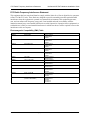
NetVanta 6355 PoE
Hardware Installation Guide
1200740E1
NetVanta 6355 PoE
1200690E1
NetVanta Quad FXS Voice Interface Module
1202691G1
NetVanta Quad FXO Voice Interface Module
1202692E1
NetVanta Dual FXS/FXO Voice Interface Module
1200695L1
NetVanta T1/PRI Voice Interface Module
1200696G1
NetVanta E1/PRI Voice Interface Module
1202862L1
NetVanta T1/FT1 Network Interface Module
1202863L1
NetVanta T1/FT1 + DSX-1 Network Interface Module
1202872L1
NetVanta Dual T1 Network Interface Module
1202869E1
NetVanta ADSL Network Interface Module, Annex A
1200868E1
NetVanta E1/FE1 Network Interface Module
1200878E1
NetVanta E1/FE1 + G.703 Network Interface Module
1200480E1
1000Base-SX Multi-Mode SFP Module
1200481E1
1000Base-LX Single-Mode SFP Module
1200852G1
CompactFlash®, 1 GB
4200368L1
Enhanced Feature Pack (Hardware and Software) for IPsec VPN Upgrade
61200740E1-34E
October 2011
Trademarks
NetVanta 6355 PoE Hardware Installation Guide
Trademarks
Any brand names and product names included in this manual are trademarks, registered trademarks, or
trade names of their respective holders.
To the Holder of the Manual
The contents of this manual are current as of the date of publication. ADTRAN reserves the right to change
the contents without prior notice.
In no event will ADTRAN be liable for any special, incidental, or consequential damages or for
commercial losses even if ADTRAN has been advised thereof as a result of issue of this publication.
Software Licensing Agreement
Each ADTRAN product contains a single license for ADTRAN-supplied software. Pursuant to the
Licensing Agreement, you may: (a) use the software on the purchased ADTRAN device only and (b) keep
a copy of the software for backup purposes. This Agreement covers all software installed on the system, as
well as any software available on the ADTRAN website. In addition, certain ADTRAN systems may
contain additional conditions for obtaining software upgrades.
Changes or modifications to this unit not expressly approved by the party responsible for
compliance could void the user’s authority to operate the equipment.
901 Explorer Boulevard
P.O. Box 140000
Huntsville, AL 35814-4000
Phone: (256) 963-8000
Copyright © 2011 ADTRAN, Inc.
All Rights Reserved.
Printed in U.S.A.
2
Copyright © 2011 ADTRAN, Inc.
61200740E1-34E
NetVanta 6355 PoE Hardware Installation Guide
Conventions
Conventions
Notes provide additional useful information.
Cautions signify information that could prevent service interruption or damage to the
equipment.
Warnings provide information that could prevent injury or endangerment to human
life.
61200740E1-34E
Copyright © 2011 ADTRAN, Inc.
3
Safety Instructions
NetVanta 6355 PoE Hardware Installation Guide
Safety Instructions
When using your telephone equipment, please follow these basic safety precautions to reduce the risk of
fire, electrical shock, or personal injury:
1. Do not use this product near water, such as a bathtub, wash bowl, kitchen sink, laundry tub, in a
wet basement, or near a swimming pool.
2. Avoid using a telephone (other than a cordless type) during an electrical storm. There is a remote
risk of shock from lightning.
3. Do not use the telephone to report a gas leak in the vicinity of the leak.
4. Use only the power cord, power supply, and batteries indicated in the manual. Do not dispose of
batteries in a fire. They may explode. Check with local codes for special disposal instructions.
5. The socket outlet shall be installed near the equipment and shall be easily accessible.
If any of the following conditions occur, unplug the product from the electrical outlet and replace the part
or contact your qualified service personnel:
1. The power cable, extension cable, or plug is damaged.
2. An object has fallen into the product.
3. The product has been exposed to water.
4. The product has been dropped or damaged.
5. The product does not operate correctly when you follow the operating instructions.
This equipment incorporates double pole/neutral fusing. If the neutral fuse opens and the
line fuse does not open, voltage could still be present in the unit.
These units contain no user-serviceable parts. They should only be serviced by qualified
service personnel.
Additional safety and regulatory guidelines, such as Waste Electrical and Electronic
Equipment (WEEE), are given in the document NetVanta Safety and Regulatory
Information (ADTRAN’s Knowledge Base article 3444) available at http://kb.adtran.com.
Save These Important Safety Instructions
4
Copyright © 2011 ADTRAN, Inc.
61200740E1-34E
NetVanta 6355 PoE Hardware Installation Guide
FCC-Required Information
FCC-Required Information
FCC regulations require that the following information be provided in this manual:
1. This equipment complies with Part 68 of Federal Communications Commission (FCC) rules and
requirements adopted by America’s Carriers Telecommunications Association (ACTA). Each
registered interface has a label that contains, among other information, a product identifier in the
format US:AAAEQ##TXXXX. If requested, provide this information to the telephone company.
2. If this equipment causes harm to the telephone network, the telephone company may temporarily
discontinue service. If possible, advance notification is given; otherwise, notification is given as
soon as possible. The telephone company will advise the customer of the right to file a complaint
with the FCC.
3. The telephone company may make changes in its facilities, equipment, operations, or procedures
that could affect the proper operation of this equipment. Advance notification and the opportunity
to maintain uninterrupted service are given.
4. If experiencing difficulty with this equipment, please contact ADTRAN for repair and warranty
information. The telephone company may require this equipment to be disconnected from the
network until the problem is corrected, or it is certain the equipment is not malfunctioning.
5. This unit contains no user-serviceable parts.
6. This equipment is designed to connect to the telephone network or premises wiring using an
FCC-compatible modular jack, which is compliant with Part 68 and requirements adopted by
ACTA.
7. The following information may be required when applying to the local telephone company for
leased line facilities:
Part Number
1202862L1
1202863L1
Registration
Number
US: HDCDENAN1202863L1
1202872L1
US: HDCDENAN1200872L1
1200695L1
US: HDCDENAN1200695L1
1202869E1
US: HDCDL01A1200869L1
1200691E1
1202692E1
1200740E1
US: HDCMM01B1200691L1
Service Type
REN/SOC
FIC
USOC
1.544 Mbps - SF
1.544 Mbps - SF and B8ZS
1.544 Mbps - ESF
1.544 Mbps - ESF and B8ZS
6.0N
04DU9-BN
04DU9-DN
04DU9-1KN
04DU9-1SN
RJ-48C
ADSL, ADSL2, ADSL2+
0.1A
Metallic
RJ-11C
Analog Loop Start/Ground Start
0.1B
02LS2/02GS2
RJ-11C
US: HDCIS01B1200740L1
8. The ringer equivalency number (REN) is useful in determining the quantity of devices you may
connect to your telephone line and still have all of those devices ring when your number is called.
In most areas, the sum of the RENs of all devices should not exceed five. To be certain of the
number of devices you may connect to your line as determined by the REN, call your telephone
company to determine the maximum REN for your calling area.
9. This equipment may not be used on coin service provided by the telephone company. Connection
to party lines is subject to state tariffs. Contact your state public utility commission or corporation
commission for information.
61200740E1-34E
Copyright © 2011 ADTRAN, Inc.
5
FCC Radio Frequency Interference Statement
NetVanta 6355 PoE Hardware Installation Guide
FCC Radio Frequency Interference Statement
This equipment has been tested and found to comply with the limits for a Class A digital device, pursuant
to Part 15 of the FCC rules. These limits are designed to provide reasonable protection against harmful
interference when the equipment is operated in a commercial environment. This equipment generates,
uses, and can radiate radio frequency energy and, if not installed and used in accordance with the
instruction manual, may cause harmful interference to radio frequencies. Operation of this equipment in a
residential area is likely to cause harmful interference in which case the user will be required to correct the
interference at his own expense.
Electromagnetic Compatibility (EMC) Table
NetVanta Module P/N and Name
1200690E1
Quad FXS VIM
1202691G1
Quad FXO VIM
1202692G1
Dual FXS/FXO VIM
1200695L1
T1/PRI VIM
1200696G1
E1/PRI VIM
1202862L1
T1/FT1 NIM
1202863L1
T1/FT1 + DSX-1 NIM
1202872L1
Dual T1 NIM
1202869E1
ADSL NIM, Annex A
1200868E1
E1/FE1 NIM
1200878E1
E1/FE1 + G.703 NIM
1202368L1
VPN Accelerator Card
(included in P/N 4200368L1)
6
NetVanta 6355 PoE
FCC Part 15 Class A
EN 55022 Class A
EN 55024
FCC Part 15 Class A
EN 55022 Class A
EN 55024
FCC Part 15 Class A
EN 55022 Class A
EN 55024
FCC Part 15 Class A
EN 55022 Class A
EN 55024
FCC Part 15 Class A
EN 55022 Class A
EN 55024
FCC Part 15 Class A
EN 55022 Class A
FCC Part 15 Class A
EN 55022 Class A
FCC Part 15 Class A
EN 55022 Class A
FCC Part 15 Class A
EN 55022 Class A
FCC Part 15 Class B
EN 55022 Class B
EN 55024
FCC Part 15 Class B
EN 55022 Class B
EN 55024
FCC Part 15 Class A
EN 55022 Class A
EN 55024
EN 61000-3-2
EN 61000-3-3
Copyright © 2011 ADTRAN, Inc.
61200740E1-34E
NetVanta 6355 PoE Hardware Installation Guide
Industry Canada Compliance Information
Industry Canada Compliance Information
Notice: The Industry Canada label applied to the product (identified by the Industry Canada logo or the
“IC:” in front of the certification/registration number) signifies that the Industry Canada technical
specifications were met.
Notice: The REN for this terminal equipment is supplied in the documentation or on the product labeling/
markings. The REN assigned to each terminal device indicates the maximum number of terminals that can
be connected to a telephone interface. The termination on an interface may consist of any combination of
devices subject only to the requirement that the sum of the RENs of all the devices should not exceed five
(5).
Canadian Emissions Requirements
This digital apparatus does not exceed the Class A limits for radio noise emissions from digital apparatus
as set out in the interference-causing equipment standard entitled “Digital Apparatus,” ICES-003 of the
Department of Communications.
Cet appareil numérique respecte les limites de bruits radioelectriques applicables aux appareils numériques
de Class A prescrites dans la norme sur le materiel brouilleur: “Appareils Numériques,” NMB-003 edictee
par le ministre des Communications.
Toll Fraud Liability
Be advised that certain security risks are inherent in the use of any telecommunications or networking
equipment, including but not limited to, toll fraud, Denial of Service (DoS) attacks, loss or theft of data, and the
unauthorized or illegal use of said equipment. ADTRAN OFFERS NO WARRANTIES, EITHER
EXPRESSED OR IMPLIED, REGARDING THE PREVENTION, DETECTION, OR DETERRENCE OF
TOLL FRAUD, NETWORKING ATTACKS, OR UNAUTHORIZED, ILLEGAL, OR IMPROPER USE OF
ADTRAN EQUIPMENT OR SOFTWARE. THEREFORE, ADTRAN IS NOT LIABLE FOR ANY LOSSES
OR DAMAGES RESULTING FROM SUCH FRAUD, ATTACK, OR IMPROPER USE, INCLUDING, BUT
NOT LIMITED TO, HUMAN AND DATA PRIVACY, INTELLECTUAL PROPERTY, MATERIAL
ASSETS, FINANCIAL RESOURCES, LABOR AND LEGAL COSTS. Ultimately, the responsibility for
securing your telecommunication and networking equipment rests with you, and you are encouraged to review
documentation regarding available security measures, their configuration and implementation, and to test such
features as is necessary for your network.
Service and Warranty
For information on the service and warranty of ADTRAN products, visit the ADTRAN website at
http://www.adtran.com/support.
61200740E1-34E
Copyright © 2011 ADTRAN, Inc.
7
Service and Warranty
8
NetVanta 6355 PoE Hardware Installation Guide
Copyright © 2011 ADTRAN, Inc.
61200740E1-34E
Table of Contents
Introduction . . . . . . . . . . . . . . . . . . . . . . . . . . . . . . . . . . . . . . . . . . . . . . . . . . . . . . . . . . . . . . . . . . . . . . . 15
Physical Description . . . . . . . . . . . . . . . . . . . . . . . . . . . . . . . . . . . . . . . . . . . . . . . . . . . . . . . . . . . . . . . 15
Features and Specifications . . . . . . . . . . . . . . . . . . . . . . . . . . . . . . . . . . . . . . . . . . . . . . . . . . . . . . . . 15
Power Over Ethernet . . . . . . . . . . . . . . . . . . . . . . . . . . . . . . . . . . . . . . . . . . . . . . . . . . . . . . . . . . . . . 16
SFP Module Slots . . . . . . . . . . . . . . . . . . . . . . . . . . . . . . . . . . . . . . . . . . . . . . . . . . . . . . . . . . . . . . . 17
Network Interface Modules Supported . . . . . . . . . . . . . . . . . . . . . . . . . . . . . . . . . . . . . . . . . . . . . . . . 17
Voice Interface Modules Supported . . . . . . . . . . . . . . . . . . . . . . . . . . . . . . . . . . . . . . . . . . . . . . . . . . 17
Shipping Contents . . . . . . . . . . . . . . . . . . . . . . . . . . . . . . . . . . . . . . . . . . . . . . . . . . . . . . . . . . . . . . . 17
NetVanta 6355 PoE Front Panel Design . . . . . . . . . . . . . . . . . . . . . . . . . . . . . . . . . . . . . . . . . . . . . . 18
NetVanta 6355 PoE Rear Panel Design . . . . . . . . . . . . . . . . . . . . . . . . . . . . . . . . . . . . . . . . . . . . . . 19
Option Modules . . . . . . . . . . . . . . . . . . . . . . . . . . . . . . . . . . . . . . . . . . . . . . . . . . . . . . . . . . . . . . . . . . . 21
Network Interface Modules . . . . . . . . . . . . . . . . . . . . . . . . . . . . . . . . . . . . . . . . . . . . . . . . . . . . . . . . 22
Voice Interface Modules . . . . . . . . . . . . . . . . . . . . . . . . . . . . . . . . . . . . . . . . . . . . . . . . . . . . . . . . . . . 28
Unit Installation . . . . . . . . . . . . . . . . . . . . . . . . . . . . . . . . . . . . . . . . . . . . . . . . . . . . . . . . . . . . . . . . . . . . 33
Tools Required . . . . . . . . . . . . . . . . . . . . . . . . . . . . . . . . . . . . . . . . . . . . . . . . . . . . . . . . . . . . . . . . . . 33
Mounting Options . . . . . . . . . . . . . . . . . . . . . . . . . . . . . . . . . . . . . . . . . . . . . . . . . . . . . . . . . . . . . . . . 34
Supplying Power to the Unit . . . . . . . . . . . . . . . . . . . . . . . . . . . . . . . . . . . . . . . . . . . . . . . . . . . . . . . . 36
Installing Network and Voice Interface Modules . . . . . . . . . . . . . . . . . . . . . . . . . . . . . . . . . . . . . . . . 36
Installing the NetVanta VPN Accelerator Card (included in P/N 4200368L1) . . . . . . . . . . . . . . . . . . 38
Installing a CompactFlash Card . . . . . . . . . . . . . . . . . . . . . . . . . . . . . . . . . . . . . . . . . . . . . . . . . . . . . 39
Appendix A.
Connector Pin Definitions. . . . . . . . . . . . . . . . . . . . . . . . . . . . . . . . . . . . . . . . . . . . . . . 41
Index . . . . . . . . . . . . . . . . . . . . . . . . . . . . . . . . . . . . . . . . . . . . . . . . . . . . . . . . . . . . . . . . . . . . . . . . . . . . . 45
61200740E1-34E
Copyright © 2011 ADTRAN, Inc.
9
Table of Contents
10
NetVanta 6355 PoE Hardware Installation Guide
Copyright © 2011 ADTRAN, Inc.
61200740E1-34E
List of Figures
Figure 1.
Figure 2.
Figure 3.
Figure 4.
Figure 5.
Figure 6.
Figure 7.
Figure 8.
Figure 9.
Figure 10.
Figure 11.
Figure 12.
Figure 13.
Figure 14.
Figure 15.
Figure 16.
Figure 17.
NetVanta 6355 PoE Front Panel Layout . . . . . . . . . . . . . . . . . . . . . . . . . . . . . . . . . . . . . . . .
NetVanta 6355 PoE Rear Panel Layout . . . . . . . . . . . . . . . . . . . . . . . . . . . . . . . . . . . . . . . . .
NetVanta T1/FT1 NIM . . . . . . . . . . . . . . . . . . . . . . . . . . . . . . . . . . . . . . . . . . . . . . . . . . . . . .
NetVanta T1/FT1 + DSX-1 NIM . . . . . . . . . . . . . . . . . . . . . . . . . . . . . . . . . . . . . . . . . . . . . . .
NetVanta Dual T1 NIM . . . . . . . . . . . . . . . . . . . . . . . . . . . . . . . . . . . . . . . . . . . . . . . . . . . . . .
NetVanta E1/FE1 NIM . . . . . . . . . . . . . . . . . . . . . . . . . . . . . . . . . . . . . . . . . . . . . . . . . . . . . .
NetVanta E1/FE1 + G.703 NIM . . . . . . . . . . . . . . . . . . . . . . . . . . . . . . . . . . . . . . . . . . . . . . .
NetVanta ADSL NIM, Annex A . . . . . . . . . . . . . . . . . . . . . . . . . . . . . . . . . . . . . . . . . . . . . . . .
NetVanta T1/PRI VIM . . . . . . . . . . . . . . . . . . . . . . . . . . . . . . . . . . . . . . . . . . . . . . . . . . . . . . .
NetVanta E1/PRI VIM . . . . . . . . . . . . . . . . . . . . . . . . . . . . . . . . . . . . . . . . . . . . . . . . . . . . . . .
NetVanta Quad FXS VIM . . . . . . . . . . . . . . . . . . . . . . . . . . . . . . . . . . . . . . . . . . . . . . . . . . . .
NetVanta Quad FXO VIM . . . . . . . . . . . . . . . . . . . . . . . . . . . . . . . . . . . . . . . . . . . . . . . . . . . .
NetVanta Dual FXS/FXO VIM . . . . . . . . . . . . . . . . . . . . . . . . . . . . . . . . . . . . . . . . . . . . . . . .
Wallmount Installation . . . . . . . . . . . . . . . . . . . . . . . . . . . . . . . . . . . . . . . . . . . . . . . . . . . . . .
NIM/VIM Installation . . . . . . . . . . . . . . . . . . . . . . . . . . . . . . . . . . . . . . . . . . . . . . . . . . . . . . . .
NetVanta VPN Card Installation . . . . . . . . . . . . . . . . . . . . . . . . . . . . . . . . . . . . . . . . . . . . . . .
CompactFlash Card Installation . . . . . . . . . . . . . . . . . . . . . . . . . . . . . . . . . . . . . . . . . . . . . . .
61200740E1-34D
Copyright © 2011 ADTRAN, Inc.
18
19
22
23
24
25
26
27
28
29
30
31
32
36
37
38
39
11
List of Figures
12
NetVanta 6355 PoE Hardware Installation Guide
Copyright © 2011 ADTRAN, Inc.
61200740E1-34D
List of Tables
Table 1.
Table 6-1.
Table 6-2.
Table 6-3.
Table 6-4.
Table 6-5.
Table 6-6.
Table 6-7.
Table 6-8.
Table 6-9.
Front Panel LED Descriptions . . . . . . . . . . . . . . . . . . . . . . . . . . . . . . . . . . . . . . . . . . . . . . . .
CONSOLE Port Pinouts . . . . . . . . . . . . . . . . . . . . . . . . . . . . . . . . . . . . . . . . . . . . . . . . . . . . .
SFP Slot Pinouts . . . . . . . . . . . . . . . . . . . . . . . . . . . . . . . . . . . . . . . . . . . . . . . . . . . . . . . . . .
10/100Base-T Ethernet Port Pinouts . . . . . . . . . . . . . . . . . . . . . . . . . . . . . . . . . . . . . . . . . . .
1000Base-T Gigabit Ethernet Port Pinouts . . . . . . . . . . . . . . . . . . . . . . . . . . . . . . . . . . . . . .
T1/E1 Connector Pinouts . . . . . . . . . . . . . . . . . . . . . . . . . . . . . . . . . . . . . . . . . . . . . . . . . . . .
DSX-1 Connector Pinouts . . . . . . . . . . . . . . . . . . . . . . . . . . . . . . . . . . . . . . . . . . . . . . . . . . .
G.703 Connector Pinouts. . . . . . . . . . . . . . . . . . . . . . . . . . . . . . . . . . . . . . . . . . . . . . . . . . . .
ADSL NIM Connector Pinouts . . . . . . . . . . . . . . . . . . . . . . . . . . . . . . . . . . . . . . . . . . . . . . . .
Analog Station (FXS) and Analog Trunk (FXO) Port Pinouts. . . . . . . . . . . . . . . . . . . . . . . . .
61200740E1-34E
Copyright © 2011 ADTRAN, Inc.
19
41
41
42
42
43
43
43
43
44
13
List of Tables
14
NetVanta 6355 PoE Hardware Installation Guide
Copyright © 2011 ADTRAN, Inc.
61200740E1-34E
1.
INTRODUCTION
This hardware installation guide describes the NetVanta 6355 Power over Ethernet (PoE) unit’s physical
characteristics, lists its features and specifications, introduces basic functionality, and provides installation
instructions.
For information on configuration for a specific application, refer to the configuration guides provided online on
the ADTRAN’s Knowledge Base at http://kb.adtran.com. For details on the command line interface (CLI), refer
to the AOS Command Reference Guide (ADTRAN’s Knowledge Base article 2219). All other related
documents are also available online on the ADTRAN’s Knowledge Base at http://kb.adtran.com.
2.
PHYSICAL DESCRIPTION
The NetVanta 6355 PoE is an Integrated Communications Platform (ICP) equipped with 24 PoE (802.3af)
10/100Base-T interfaces capable of supplying the full 15.4 watts and two Gigabit Ethernet interfaces accessed
via a fixed RJ-45 connector or small form-factor pluggable (SFP) slots for fiber connectivity. The
NetVanta 6355 PoE is a 1U-high, rack-mountable metal enclosure that includes a universal AC power supply
and provides Voice over Internet Protocol (VoIP) capability for up to 50 user registrations.
This section includes a list of features, a list of supported modules, a list of shipping contents, and a description
of the unit’s front and rear panel designs. For additional information, refer to the following sections:
•
•
•
•
•
Mounting Options on page 34
Supplying Power to the Unit on page 36
Installing Network and Voice Interface Modules on page 36
Installing the NetVanta VPN Accelerator Card (included in P/N 4200368L1) on page 38
Installing a CompactFlash Card on page 39
Features and Specifications
•
•
•
•
•
•
•
•
•
•
•
•
•
•
•
•
24-port PoE (802.3af) injector (15.4 watts per port)
Provides 370 watts of power over spare pair for PoE
Optional CompactFlash®
Optional virtual private network (VPN)
Feature-rich ADTRAN Operating System (AOS)
Recognizable CLI and user-friendly, Web-based graphical user interface (GUI)
Telnet, HTTP, SSL, SSH, craft/console port, or SNMP management options
XAUTH including RADIUS and RSA SecurID
Flash memory supports dual images of AOS
TFTP, FTP, and XMODEM for firmware upgrades and maintenance updates
LLDP (802.1AB) for discovering neighboring peers
Optional combination SFP/1000Base-T Gigabit Ethernet port for stacking and uplink requirements
Stacking (up to 16 switches) with single IP address management
Compatible with ADTRAN’s other VPN-equipped NetVanta products
Auto-rate, auto-duplexing, and auto-MDI/MDI-X sensing
Support for VLAN trunking and GVRP with up to 255 active VLANs (802.1Q)
61200740E1-34D
Copyright © 2011 ADTRAN, Inc.
15
Physical Description
•
•
•
•
•
•
•
•
•
•
•
•
•
•
•
•
•
•
•
•
•
•
•
•
•
•
NetVanta 6355 PoE Hardware Installation Guide
Class of service (CoS) (802.1p) and DiffServ for traffic prioritization with weighted round robin (WRR)
and strict priority queuing
Four queues per egress port
DiffServ-to-802.1p mapping
Spanning Tree/Rapid Spanning Tree support (802.1D/802.1w)
Storm control, link aggregation (802.3ad), and port mirroring
MAC-based port security
Full-featured onboard IP access router supports all NetVanta 3000 Series routing features
Interchangeable network interface modules (NIMs): T1/FT1, T1/FT1 + DSX-1, Dual T1, and ADSL
Annex A available
Interchangeable voice interface modules (VIMs): Quad FXS, Quad FXO, Dual FXS/FXO, E1/PRI, and
T1/PRI available
Standards-based BGP, OSPF, RIP, and static routing support
Bridging across the WAN
Ideal for Frame Relay, Multilink Frame Relay, PPP, Multilink PPP (MLPPP), PPPoE, or ATM (ADSL
NIM) networks
Integral stateful inspection firewall protects against denial of service (DoS) attacks
Quality of service (QoS) with low latency queuing (LLQ) and weighted fair queuing (WFQ), and
DiffServ marking
Frame Relay and PPP fragmentation to avoid latency
VLAN (802.1Q) trunking/interVLAN routing and bridging
Network address translation (NAT/NAPT) and NAT Traversal version 2
NAT-compatible SIP ALG
DHCP client, server, and relay
IPsec VPN upgrade supporting 500 tunnels and DES/3DES/AES encryption
Single combination 10/100/1000Base-T Ethernet port/SFP module slot for high-speed uplink or
stacking requirements
6.8 Gbps nonblocking switching capacity
1U, 19-inch rackmount metal enclosure
1.7-inch H x 17.2-inch W x 7.8-inch D
Auto-ranging power (100 to 250 VAC, 50/60 Hz)
Operating temperature: 0°C to 50°C
Power Over Ethernet
The NetVanta 6355 PoE interfaces provide the ability to detect attached powered devices (PDs) and deliver
48 VDC to the PD via existing CAT 5 cabling. The PoE interfaces are fully compliant with the IEEE 802.3af
PoE standard. By default, the PoE ports automatically discover and provide power to IEEE-compliant PDs.
16
Copyright © 2011 ADTRAN, Inc.
61200740E1-34D
NetVanta 6355 PoE Hardware Installation Guide
Physical Description
SFP Module Slots
The NetVanta 6355 PoE supports two SFP slots that accept a number of industry standard SFP modules. The
SFP modules provide Gigabit Ethernet connectivity over fiber for high-speed uplinks or switch stacking. The
following modules are available for purchase (both of these modules require fiber optic cable with LC
connectors):
•
•
1200480E1
1200481E1
1000Base-SX Multi-Mode SFP Module
1000Base-LX Single-Mode SFP Module
Network Interface Modules Supported
The NetVanta 6355 PoE contains two NIM/VIM slots on the rear panel that support the following modules in
data applications:
•
•
•
•
•
•
1202862L1
1202863L1
1200872L1
1200868E1
1200878E1
1202869E1
T1/FT1 NIM
T1/FT1 + DSX-1 NIM
Dual T1 NIM
E1/FE1 NIM
E1/FE1 + G.703 NIM
ADSL NIM, Annex A
Voice Interface Modules Supported
The NetVanta 6355 PoE NIM/VIM slots on the rear panel support the following VIMs in voice applications:
•
•
•
•
•
1200690E1
1202691G1
1202692G1
1200695L1
1200696G1
Quad FXS VIM
Quad FXO VIM
Dual FXS/FXO VIM
T1/PRI VIM
E1/PRI VIM
Shipping Contents
Each NetVanta 6355 PoE unit is shipped in its own cardboard shipping carton. Open each carton carefully, and
avoid deep penetration into the carton with sharp objects.
After unpacking the unit, inspect it for possible shipping damage. If the equipment has been damaged in transit,
immediately file a claim with the carrier and contact ADTRAN Customer Service (refer to the Repair and
Replacement section of the Support page on the ADTRAN website at http://www.adtran.com/support).
Shipments of the NetVanta 6355 PoE include the following items:
•
•
•
•
NetVanta 6355 PoE base unit
Quick start guide
A detachable power cable with a grounded, three-prong plug
Mounting brackets and screws
61200740E1-34D
Copyright © 2011 ADTRAN, Inc.
17
Physical Description
NetVanta 6355 PoE Hardware Installation Guide
NetVanta 6355 PoE Front Panel Design
The NetVanta 6355 PoE front panel is shown in Figure 1 on page 18. Table 1 on page 19 describes all of the
LEDs, and Appendix A on page 41 shows the pinouts for the connectors.
NetVanta 6355 PoE Front Panel Features
10/100Base-T Ethernet Interfaces
The NetVanta 6355 PoE front panel contains 24 10/100Base-T Ethernet interfaces (RJ-45). These
interfaces are consecutively numbered 1 through 24, from left to right, with the numbers screened
directly above each port. Status LEDs for each of these interfaces are located directly over these
numbers.
The NetVanta 6355 PoE also has green and red PoE status LEDs located in the upper-left and
upper-right corners (respectively) of each Ethernet connector.
Gigabit Ethernet Interfaces/SFP Slots
The NetVanta 6355 PoE front panel contains two Gigabit Ethernet interfaces that provide two fixed
RJ-45 connectors and two standard SFP slots for connectivity over fiber. (Use either the RJ-45
connectors or the SFP slots. The fiber slots have precedence.) These interfaces are labeled G1 and G2,
and the status LEDs are located above the SFP slots.
Status LEDs
The status LEDs are located to the lower left of RJ-45 port 1. The SLOT 1 LED reflects the status of a
NIM/VIM installed in NIM/VIM option SLOT 1 (located on the rear panel). The SLOT 2 LED reflects
the status of a NIM/VIM installed in NIM/VIM option SLOT 2 (located on the rear panel). The STAT
LED indicates the unit’s status.
NetVanta 6355
Figure 1. NetVanta 6355 PoE Front Panel Layout
18
Copyright © 2011 ADTRAN, Inc.
61200740E1-34D
NetVanta 6355 PoE Hardware Installation Guide
Physical Description
Table 1. Front Panel LED Descriptions
LED
STAT
Port LEDs
(1 through 24, G1, G2)
SLOT 1/SLOT 2
Power over Ethernet
Status LEDs
Color
Indication
Off
Unit is not receiving power.
Green (solid)
Power is on and self-test passed.
Green (flashing)
On power up, the STAT LED flashes rapidly for five
seconds, during which time the user may escape to boot
mode from the CONSOLE port.
Red (solid)
Power is on, but the self-test failed or the boot code could
not be booted.
Off
Port is administratively disabled or does not have a
connection.
Green (solid)
Port is enabled and has a connection.
Amber (flashing)
Port has activity (transmit or receive).
Off
No NIM/VIM installed or interface is administratively down.
Green (solid)
NIM/VIM module is up and everything is okay.
Green (flashing)
Port has activity (transmit or receive).
Amber (solid)
NIM/VIM module is in test.
Red (solid)
An alarm is occurring on the interface.
Green (solid)
Power is being applied (48 V) to the interface.
Red (solid)
Fault is detected on the interface.
NetVanta 6355 PoE Rear Panel Design
The NetVanta 6355 PoE rear panel is shown below. Refer to Appendix A on page 41 for pinouts.
100-250 VAC
50-60Hz
MOH
0/1
CF
0/2
0/1
0/2
ETH 0/0
CONSOLE
DOOR
RELAY
PAGE
SLOT 1
SLOT 2
ANALOG STA
ANALOG TRK
NC NO COM
Figure 2. NetVanta 6355 PoE Rear Panel Layout
NetVanta 6355 PoE Rear Panel Interfaces
CompactFlash
The CompactFlash slot (labeled CF) supplies nonvolatile configuration and compressed code storage.
The NetVanta 6355 PoE supports only ADTRAN-provided CompactFlash (16 MB to 1 GB) (refer to
the part number on the front cover of this manual).
NIM/VIM Option Slots
The two NIM/VIM option slots (labeled SLOT 1 and SLOT 2) accept a variety of NIM/VIM option
modules (refer to Option Modules on page 21).
FXS and FXO Ports
The two FXS interfaces (labeled ANALOG STA 0/1 and 0/2) and two FXO interfaces (labeled
ANALOG TRK 0/1 and 0/2) provide FXS and FXO connectivity, respectively.
61200740E1-34D
Copyright © 2011 ADTRAN, Inc.
19
Physical Description
NetVanta 6355 PoE Hardware Installation Guide
During power outages, the FXS interfaces are connected directly to the FXO interfaces. This feature is
called life line mode, and allows customers to make analog calls even when the power is out.
For the NetVanta 6355 PoE, devices connected to the FXS (ANALOG STA) ports must
be ACTA/FCC Part 68 compliant due to the direct connection to the public switched
telephone network (PSTN) in life line mode.
MOH
Reserved for future use.
Page
Reserved for future use.
10/100Base-T Ethernet Interface
The Ethernet port (ETH 0/0) is an RJ-45 connector. The Ethernet port provides the following:
•
•
•
•
10Base-T or 100Base-T with a single connector
Autonegotiation
CSMA/CD
IEEE 802.3 compatibility
Door Relay
Reserved for future use.
CONSOLE Interface
The CONSOLE interface is an EIA-232 serial port (DCE), which provides for local management and
configuration (via a DB-9 female connector).
Connection directly to an external modem requires a cross-over cable.
Power Connection
The rear panel has a power input to the AC universal power supply. Please refer to Supplying Power to
the Unit on page 36 for connection details.
20
Copyright © 2011 ADTRAN, Inc.
61200740E1-34D
NetVanta 6355 PoE Hardware Installation Guide
3.
Option Modules
OPTION MODULES
The NetVanta 6355 PoE supports several option modules designed to meet a variety of networking
requirements. The option modules include plug-in NIMs and VIMs.
NIMs/VIMs are cards that plug directly into the option module slot located on the rear of the base unit. These
cards provide the following types of interfaces:
•
•
•
•
•
•
•
•
•
•
•
NetVanta T1/FT1 NIM (P/N 1202862L1) on page 22
NetVanta T1/FT1 + DSX-1 NIM (P/N 1202863L1) on page 23
NetVanta Dual T1 NIM (P/N 1202872L1) on page 24
NetVanta E1/FE1 NIM (P/N 1200868E1) on page 25
NetVanta E1/FE1 + G.703 NIM (P/N 1200878E1) on page 26
NetVanta ADSL NIM, Annex A (P/N 1202869E1) on page 27
NetVanta T1/PRI VIM (P/N 1200695L1) on page 28
NetVanta E1/PRI VIM (P/N 1200696G1) on page 29
NetVanta Quad FXS VIM (P/N 1200690E1) on page 30
NetVanta Quad FXO VIM (P/N 1202691G1) on page 31
NetVanta Dual FXS/FXO VIM (P/N 1202692G1) on page 32
This section describes each module, providing individual card specifications and features. Refer to Appendix A
on page 41 for pinout information. Installing Network and Voice Interface Modules on page 36 provides
information on card installation.
61200740E1-34D
Copyright © 2011 ADTRAN, Inc.
21
Option Modules
NetVanta 6355 PoE Hardware Installation Guide
Network Interface Modules
NetVanta T1/FT1 NIM (P/N 1202862L1)
The NetVanta T1/FT1 NIM (see Figure 3) provides a T1 WAN interface for the NetVanta. This module provides
a full T1 or fractional T1 network interface. See Table 6-5 on page 43 for the WAN-T1 connector pinouts. An
optional DIM is required for dial backup applications. Dial backup is not supported at this time.
WAN-T1
DBU
Figure 3. NetVanta T1/FT1 NIM
Features and Specifications
Operating Modes
Diagnostics
•
•
•
•
Frame Relay, Multilink Frame Relay
PPP, MLPPP
HDLC
•
T1/FT1 Interface
•
•
•
•
•
•
•
•
•
Supported Standards: AT&T TR 62411,
AT&T TR 65016, ANSI T1.403,
Bellcore TR 194
Line Rate: 1.544 Mbps +75 bps
Line Code: AMI or B8ZS
Framing: D4 (SF) or ESF
FT1 Line Rate: DS0 channelized (multiples
of 64 kbps)
Input Signal: 0 to -36 dB (DS1)
Line Build-Out: 0, -7.5, -15, -22.5 dB
(long), 0 to 655 ft (short)
DS0 Assignment: Programmable
Connector: RJ-48C
Clock Source
•
•
Line
Internal
•
•
Compliance
•
•
•
•
EMC - see Electromagnetic Compatibility
(EMC) Table on page 6.
ACTA/FCC Part 68
IC CS-03
UL/CUL 60950
Environmental
•
•
•
Operating Temperature: 0°C to 50°C
Storage Temperature: -20°C to 70°C
Relative Humidity: Up to 95 percent,
noncondensing
Physical
•
22
Test Pattern Generation and Detection:
511, QRSS, all ones, all zeros
Network loopbacks (local and remote);
responds to both inband and FDL loop
codes
Alarm generation and detection
Network and user sets of performance data
(15 minutes and 24 hours)
Dimensions: 2.75-inch W x 4.25-inch D
Copyright © 2011 ADTRAN, Inc.
61200740E1-34D
NetVanta 6355 PoE Hardware Installation Guide
Option Modules
NetVanta T1/FT1 + DSX-1 NIM (P/N 1202863L1)
The NetVanta T1/FT1 + DSX-1 NIM (see Figure 4) provides a T1 WAN interface for the NetVanta, a full or
fractional T1 network interface, and a DSX-1 interface. See Table 6-5 on page 43 for the WAN-T1 connector
pinouts and Table 6-6 on page 43 for the DSX-1 connector pinouts. An optional DIM is required for dial backup
applications. Dial backup is not supported at this time.
WAN-T1
DSX-1
DBU
Figure 4. NetVanta T1/FT1 + DSX-1 NIM
Features and Specifications
Operating Modes
Clock Source
•
•
•
•
•
•
Frame Relay, Multilink Frame Relay
PPP, MLPPP
HDLC
Line
Internal
Through
T1/FT1 Interface
Diagnostics
•
•
•
•
•
•
•
•
•
•
Supported Standards: AT&T TR 62411,
AT&T TR 65016, ANSI T1.403,
Bellcore TR 194
Line Rate: 1.544 Mbps +75 bps
Line Code: AMI or B8ZS
Framing: D4 (SF) or ESF
FT1 Line Rate: DS0 channelized (multiples
of 56/64 kbps)
Input Signal: 0 to -36 dB (DS1)
Line Build-Out: 0, -7.5, -15, -22.5 dB
(long), 0 to 655 ft (short)
DS0 Assignment: Programmable
Connector: RJ-48C
DSX-1 Interface
•
•
•
•
•
•
•
•
•
Line Interface: DSX-1 per ANSI T1.102
DSX Receiver Input Range: -10 dBdsx to
+6 dBdsx
Line Rate: 1.544 Mbps
Capacity: 1 to 24 DS0s
Line Codes: AMI, B8ZS
DSX-1 Interface to PBX
Framing: D4 (SF) or ESF
Line Length: 0 to 655 feet and -7.5 dB
Connector: RJ-48C
61200740E1-34D
•
•
•
Test Pattern Generation and Detection:
511, QRSS, all ones, all zeros
Network loopbacks (local and remote);
responds to inband and FDL loop codes (T1
interface only)
Alarm generation and detection
Network and user sets of performance data
(15 minutes and 24 hours)
Compliance
•
•
•
•
EMC - see Electromagnetic Compatibility
(EMC) Table on page 6.
ACTA/FCC Part 68
IC CS-03
UL/CUL 60950
Environmental
•
•
•
Operating Temperature: 0°C to 50°C
Storage Temperature: -20°C to 70°C
Relative Humidity: Up to 95 percent,
noncondensing
Physical
•
Dimensions: 2.75-inch W x 4.25-inch D
Copyright © 2011 ADTRAN, Inc.
23
Option Modules
NetVanta 6355 PoE Hardware Installation Guide
NetVanta Dual T1 NIM (P/N 1202872L1)
The NetVanta Dual T1 NIM (see Figure 5) provides two WAN T1 interfaces for the NetVanta. See Table 6-5 on
page 43 for the pinouts. An optional DIM is required for dial backup applications. Dial backup is not supported
at this time.
WAN T1/1 WAN T1/2
DBU
Figure 5. NetVanta Dual T1 NIM
Features and Specifications
Operating Modes
Diagnostics
•
•
•
•
Frame Relay, Multilink Frame Relay
PPP, MLPPP
HDLC
•
T1 Interface
•
•
•
•
•
•
•
•
•
Supported Standards: AT&T TR 62411,
AT&T TR 65016, ANSI T1.403,
Bellcore TR 194
Line Rate: 1.544 Mbps +75 bps
Line Code: AMI or B8ZS
Framing: D4 (SF) or ESF
FT1 Line Rate: DS0 channelized
(multiples of 64 kbps)
Input Signal: 0 to -36 dB (DS1)
Line Build-Out: 0, -7.5, -15, -22.5 dB
(long), 0 to 655 ft (short)
DS0 Assignment: Programmable
Connector: RJ-48C
Clock Source
•
•
•
Line
Internal
Through
•
•
Compliance
•
•
•
•
EMC - see Electromagnetic
Compatibility (EMC) Table on page 6.
ACTA/FCC Part 68
IC CS-03
UL/CUL 60950
Environmental
•
•
•
Operating Temperature: 0°C to 50°C
Storage Temperature: -20°C to 70°C
Relative Humidity: Up to 95 percent,
noncondensing
Physical
•
24
Test Pattern Generation and Detection:
QRSS, 511, 215 - 1, 220 - 1, all ones,
all zeros
Network loopbacks (local and remote);
responds to both inband and FDL loop
codes
Alarm generation detection
Network performance data (15 minutes
and 24 hours)
Dimensions: 2.75-inch W x 4.25-inch D
Copyright © 2011 ADTRAN, Inc.
61200740E1-34D
NetVanta 6355 PoE Hardware Installation Guide
Option Modules
NetVanta E1/FE1 NIM (P/N 1200868E1)
The NetVanta E1/FE1 NIM (shown in Figure 6) provides a WAN-E1 interface for the NetVanta 7000
Series, meeting the requirements of ITU-T G.703/G.704. The module provides a single 2.048 Mbps
network interface. See Table A-6 on page 43 for the pinouts. An optional DIM is required for dial backup
applications. Dial backup is not supported at this time
WAN-E1
DBU
Figure 6. NetVanta E1/FE1 NIM
Features and Specifications
Operating Modes
Compliance
•
•
•
•
Frame Relay, multilink Frame Relay
PPP, MLPPP
HDLC
WAN-E1 Interface
•
•
•
•
•
•
•
Supported Standards: ITU G.703,
ITU-T G.704 (CRC-4), ITU-T G.823,
ITU-T G.797
Line Rate: 2.048 Mbps +50 PPM
Line Code: AMI or HDB3
Framing: FAS with optional CRC-4
FE1 Line Rate: Channelized timeslot (in
multiples of 64 kbps)
Receiver Sensitivity: -30 dB
Connector: RJ-48C
•
•
•
•
•
•
EMC - see Electromagnetic
Compatibility (EMC) Table on page 6.
AS/ACIF S016
ETSI TBR 12/TBR 13
EN 60950
IEC 60950
AS/NZS 60950
RoHS compliant (1200868E1 only)
(Telecommunications exemption)
Environmental
•
•
•
Operating Temperature: 0°C to 50°C
Storage Temperature: -20°C to 70°C
Relative Humidity: Up to 95 percent,
noncondensing
Clock Source
Physical
•
•
•
Network
Internal
Dimensions: 2.75-inch W x 4.25-inch D
Diagnostics
•
•
•
•
Test Pattern Generation and Detection:
QRSS, 511, all ones, all zeros
Network loopbacks
Network performance data (15 minutes
and 24 hours)
Alarm generation and detection
61200740E1-34D
Copyright © 2011 ADTRAN, Inc.
25
Option Modules
NetVanta 6355 PoE Hardware Installation Guide
NetVanta E1/FE1 + G.703 NIM (P/N 1200878E1)
The NetVanta E1/FE1 + G.703 NIM (shown in Figure 7) provides a single WAN-E1 interface
(2.043 Mbps) with user-selectable TS0 assignment and a G.703 drop port that can be used to drop and
insert traffic to an E1 PBX. See Table A-6 on page 43 for the WAN-E1 pinouts. See Table A-8 on page 43
for the G.703 pinouts. An optional DIM is required for dial backup applications. Dial backup is not supported at
this time
WAN-E1
G.703
DBU
Figure 7. NetVanta E1/FE1 + G.703 NIM
Features and Specifications
Operating Modes
Diagnostics
•
•
•
•
Frame Relay, multilink Frame Relay
PPP, MLPPP
HDLC
WAN-E1 Interface
•
•
•
•
•
•
•
Supported Standards: ITU G.703,
ITU-T G.704 (CRC-4), ITU-T G.823,
ITU-T G.797
Line Rate: 2.048 Mbps +50 PPM
Line Code: AMI or HDB3
Framing: FAS with optional CRC-4
FE1 Line Rate: Channelized timeslot (in
multiples of 64 kbps)
Receiver Sensitivity: -30 dB
Connector: RJ-48C
G.703 Interface
•
•
•
•
•
•
26
Receiver Sensitivity: -30 dB
Line Rate: 2.048 Mbps +50 PPM
Line Code: AMI or HDB3
Framing: FAS with optional CRC-4
Capacity: 1 to 31 timeslots
Connector: RJ-48C
•
•
•
Test Pattern Generation and Detection:
QRSS, 511, all ones, all zeros
Network loopbacks
Network performance data (15 minutes
and 24 hours)
Alarm generation and detection
Compliance
•
•
•
•
•
•
•
EMC - see Electromagnetic
Compatibility (EMC) Table on page 6.
AS/ACIF S016
ETSI TBR 12/TBR 13
EN 60950
IEC 60950
AS/NZS 60950
RoHS compliant (1200878E1 only)
(Telecommunications exemption)
Environmental
•
•
•
Operating Temperature: 0°C to 50°C
Storage Temperature: -20°C to 70°C
Relative Humidity: Up to 95 percent,
noncondensing
Clock Source
Physical
•
•
•
•
Network
Internal
Through
Dimensions: 2.75-inch W x 4.25-inch D
Copyright © 2011 ADTRAN, Inc.
61200740E1-34D
NetVanta 6355 PoE Hardware Installation Guide
Option Modules
NetVanta ADSL NIM, Annex A (P/N 1202869E1)
The NetVanta ADSL, Annex A NIM (see Figure 8) adds ADSL capability to the NetVanta. The module
provides a single ADSL, ADSL2, or ADSL2+ network interface to support rates up to 25 Mbps. See Table 6-8
on page 43 for the pinouts. An optional DIM is required for dial backup applications. Dial backup is not
supported at this time.
WAN-ADSL
DBU
Figure 8. NetVanta ADSL NIM, Annex A
Features and Specifications
DSL Interface
Compliance
•
•
•
•
ADSL over POTS, Annex A
Supported Standards:
– ITU-T G.992.1 Annex A (G.dmt)
– ITU-T G.992.2 Annex A (G.lite)
– ITU-T G.992.3 Annex A ADSL2
(G.dmt.bis)
– ITU-T G.992.5 Annex A ADSL2+
– ITU-T G.992.3 Annex L READSL2
– ANSI T1.413 Issue 2
Connector: RJ-1C (6-pin jack, inner pair)
•
•
•
•
•
•
•
•
•
ATM
•
•
•
•
•
•
•
Multiple Protocol over AAL5
(RFC 2684)
PPP over ATM (RFC 2364)
PPP over Ethernet (RFC 2516)
ATM Forum UNI 3.1/4.0 PVC
ATM class of service (UBR)
ATM F5 OAM
Up to 16 virtual circuits
61200740E1-34D
EMC - see Electromagnetic
Compatibility (EMC) Table on page 6.
ACTA/FCC Part 68
AS/ACIF S043
AS/ACIF S002
IC CS-03
EN 60950
IEC 60950
UL/CUL 60950
AS/NZS 60950
RoHS compliant (Telecommunications
exemption)
Environmental
•
•
•
Operating Temperature: 0°C to 50°C
Storage Temperature: -20°C to 70°C
Relative Humidity: Up to 95 percent,
noncondensing
Physical
•
Dimensions: 2.75-inch W x 4.25-inch D
Copyright © 2011 ADTRAN, Inc.
27
Option Modules
NetVanta 6355 PoE Hardware Installation Guide
Voice Interface Modules
NetVanta T1/PRI VIM (P/N 1200695L1)
The NetVanta T1/PRI VIM (see Figure 9) adds T1 voice capability to the NetVanta. See Table 6-5 on page 43
for the T1 connector pinouts. An optional DIM is required for dial backup applications. Dial backup is not
supported at this time.
Figure 9. NetVanta T1/PRI VIM
Features and Specifications
Operating Modes
Diagnostics
•
•
Primary Rate ISDN (PRI), CAS
T1 Interface
•
•
•
•
•
•
•
•
•
Supported Standards: AT&T TR 62411,
AT&T TR 54016, Bellcore TR 194,
ANSI T1.403
Line Rate: 1.544 Mbps +75 bps
Line Code: AMI or B8ZS
Framing: D4 (SF) or ESF
FT1 Line Rate: DS0 channelized
(multiples of 64 kbps)
Input Signal: 0 to -36 dB (DS1)
Line Build-Out: 0, -7.5, -15, -22.5 dB
(long), 0 to 655 ft (short)
DS0 Assignment: Programmable
Connector: RJ-48C
Clock Source
•
•
•
Line
Internal
System
•
•
•
Test Pattern Generation and Detection:
QRSS, 215 - 1, all ones, all zeros
Network loopbacks (local and remote);
responds to both inband and FDL loop
codes
Alarm generation detection
Network performance data (15 minutes
and 24 hours)
Compliance
•
•
•
•
EMC - see Electromagnetic Compatibility
(EMC) Table on page 6.
ACTA/FCC Part 68
IC CS-03
UL/CUL 60950
Environmental
•
•
•
Operating Temperature: 0°C to 50°C
Storage Temperature: -20°C to 70°C
Relative Humidity: Up to 95 percent,
noncondensing
Physical
•
28
Dimensions: 2.75-inch W x 4.25-inch D
Copyright © 2011 ADTRAN, Inc.
61200740E1-34D
NetVanta 6355 PoE Hardware Installation Guide
Option Modules
NetVanta E1/PRI VIM (P/N 1200696G1)
The NetVanta E1/PRI VIM (see Figure 10) adds E1 voice capability to the NetVanta. See
Table 6-5 on page 43 for the E1 connector pinouts. An optional DIM is required for dial backup
applications. Dial backup is not supported at this time.
Figure 10. NetVanta E1/PRI VIM
Features and Specifications
Operating Modes
Compliance
•
•
Primary Rate ISDN (PRI), CAS
E1 Interface
•
•
•
•
•
•
•
Supported Standards: ITU-T G.703,
ITU-T G.704 (CRC-4), ITU-T G.732,
ITU-T G.823
Line Rate: 2.048 Mbps +50 bps
Line Code: AMI or HDB3
Framing: TS-16, CRC-4, double frame
FE1 Line Rate: Channelized timeslot
(multiples of 64 kbps)
Receiver Sensitivity: -36 dB
Connector: RJ-48C
Clock Source
•
•
•
Line
Internal
System
•
•
•
•
•
•
EMC - see Electromagnetic Compatibility
(EMC) Table on page 6.
AS/ACIF S016
ETSI TBR 12/TBR 13
EN 60950-1
IEC 60950-1
AS/NZS 60950-1
RoHS compliant (Telecommunications
exemption)
Environmental
•
•
•
Operating Temperature: 0°C to 50°C
Storage Temperature: -20°C to 70°C
Relative Humidity: Up to 95 percent,
noncondensing
Physical
•
Dimensions: 2.75-inch W x 4.25-inch D
Diagnostics
•
•
•
•
Test Pattern Generation and Detection:
QRSS, 511, all ones, all zeros
Network loopbacks
Alarm generation detection
Network and user sets of performance data
(15 minutes and 24 hours)
61200740E1-34D
Copyright © 2011 ADTRAN, Inc.
29
Option Modules
NetVanta 6355 PoE Hardware Installation Guide
NetVanta Quad FXS VIM (P/N 1200690E1)
The NetVanta Quad FXS VIM (see Figure 11) adds voice capability to the NetVanta. See Table 6-9 on page 44
for the FXS connector pinouts.
1
2
3
4
ANALOG
VIM
STATIONS
Figure 11. NetVanta Quad FXS VIM
Features and Specifications
Analog Voice Ports
Environmental
•
•
•
•
•
Loop Start (LS), Ground Start (GS)
Normal and reverse battery operation
Transmission Level
•
•
FXS Receive Gain: -12 to +6 dB,
0.1 dB steps
FXS Transmit Gain: -12 to +6 dB,
0.1 dB steps
Operating Temperature: 0°C to 50°C
Storage Temperature: -20°C to 70°C
Relative Humidity: Up to 95 percent,
noncondensing
Physical
•
Dimensions: 2.75-inch W x 4.25-inch D
Compliance
•
•
EMC - see Electromagnetic Compatibility
(EMC) Table on page 6.
UL/CUL 60950
Devices connected to the FXS (ANALOG STA) ports must be ACTA/FCC Part 68
compliant due to the direct connection to the PSTN in life line mode.
30
Copyright © 2011 ADTRAN, Inc.
61200740E1-34D
NetVanta 6355 PoE Hardware Installation Guide
Option Modules
NetVanta Quad FXO VIM (P/N 1202691G1)
The NetVanta Quad FXO VIM (see Figure 12) adds voice capability to the NetVanta. See Table 6-9 on page 44
for the FXO connector pinouts.
1
2
3
4
ANALOG
VIM
TRUNKS
Figure 12. NetVanta Quad FXO VIM
Features and Specifications
Analog Voice Ports
Environmental
•
•
•
•
•
Loop Start (LS), Ground Start (GS)
Normal and reverse battery operation
Transmission Level
•
•
FXO Transmit Gain: -6 to +10 dB,
0.1 dB steps
FXO Receive Gain: -6 to +10 dB,
0.1 dB steps
Operating Temperature: 0°C to 50°C
Storage Temperature: -20°C to 70°C
Relative Humidity: Up to 95 percent,
noncondensing
Physical
•
Dimensions: 2.75-inch W x 4.25-inch D
Compliance
•
•
•
EMC - see Electromagnetic
Compatibility (EMC) Table on page 6.
UL/CUL 60950
ACTA/FCC Part 68
61200740E1-34D
Copyright © 2011 ADTRAN, Inc.
31
Option Modules
NetVanta 6355 PoE Hardware Installation Guide
NetVanta Dual FXS/FXO VIM (P/N 1202692G1)
The NetVanta Dual FXS/FXO VIM (see Figure 13) adds voice capability to the NetVanta. See Table 6-9 on
page 44 for the FXS/FXO connector pinouts.
1
2
1
2
ANALOG
VIM
STATIONS
TRUNKS
Figure 13. NetVanta Dual FXS/FXO VIM
Features and Specifications
Analog Voice Ports
Compliance
•
•
•
•
Dual FXS and Dual FXO ports
Loop Start (LS), Ground Start (GS)
Normal and reverse battery operation
Transmission Level
•
•
•
•
FXS Receive Gain: -12 to +6 dB,
0.1 dB steps
FXS Transmit Gain: -12 to +6 dB,
0.1 dB steps
FXO Transmit Gain: -6 to +10 dB,
0.1 dB steps
FXO Receive Gain: -6 to +10 dB,
0.1 dB steps
•
•
EMC - see Electromagnetic
Compatibility (EMC) Table on page 6.
UL/CUL 60950
ACTA/FCC Part 68 (FXO ports)
Environmental
•
•
•
Operating Temperature: 0°C to 50°C
Storage Temperature: -20°C to 70°C
Relative Humidity: Up to 95 percent,
noncondensing
Physical
•
Dimensions: 2.75-inch W x 4.25-inch D
Devices connected to the FXS (ANALOG STA) ports must be ACTA/FCC Part 68
compliant due to the direct connection to the PSTN in life line mode.
32
Copyright © 2011 ADTRAN, Inc.
61200740E1-34D
NetVanta 6355 PoE Hardware Installation Guide
4.
Unit Installation
UNIT INSTALLATION
The instructions and guidelines provided in this section cover hardware installation topics, such as mounting
options, supplying power to the unit, and installing option cards. These instructions are presented as follows:
•
•
•
•
•
Mounting Options on page 34
Supplying Power to the Unit on page 36
Installing Network and Voice Interface Modules on page 36
Installing the NetVanta VPN Accelerator Card (included in P/N 4200368L1) on page 38
Installing a CompactFlash Card on page 39
For information on configuration for a specific application, refer to the configuration guides provided online on
the ADTRAN’s Knowledge Base at http://kb.adtran.com.
To prevent electrical shock, do not install equipment in a wet location or during a
lightning storm.
Electronic modules can be damaged by static electrical discharge. Before handling
modules, put on an antistatic discharge wrist strap to prevent damage to electrical
components. Place modules in antistatic packing material when transporting or storing.
When working on modules, always place them on an approved antistatic mat that is
electrically grounded.
The NetVanta 6355 PoE is intended to be installed, maintained, and serviced by qualified
service personnel only and should be installed in a restricted access location as described
in UL/IEC 60950-1.
Ethernet and PoE cables are intended for intra building use only. They should not be run
outside the building.
Tools Required
The customer-provided tools required for the hardware installation of the NetVanta are:
•
•
•
•
Ethernet cables
Network cables (module dependent)
DSX-1 cable (T1/FT1 + DSX-1 module only)
Phillips-head screwdriver (rack-mounted applications only)
To access the CLI of the NetVanta, you will also need a PC with terminal emulation
software and a console port cable. Instructions on how to access the CLI are available in
the quick start guide shipped with your unit or online at ADTRAN’s Knowledge Base.
61200740E1-34D
Copyright © 2011 ADTRAN, Inc.
33
Unit Installation
NetVanta 6355 PoE Hardware Installation Guide
Mounting Options
The unit may be installed in rackmount, wallmount, or tabletop configurations. The following sections provide
step-by-step instructions for rack mounting and wall mounting.
If you have purchased the VPN Accelerator Card for your NetVanta 6355 PoE, install it
first (refer to Installing the NetVanta VPN Accelerator Card (included in P/N 4200368L1)
on page 38).
Rack Mounting the NetVanta
The NetVanta is a 1U-high, rack-mountable unit that can be installed into a 19-inch equipment rack. The
following steps guide you in mounting the NetVanta into a rack.
•
•
•
•
•
If installed in a closed or multi-unit rack assembly, the operating ambient temperature
of the rack environment may be greater than room ambient temperature. Therefore,
consideration should be given to installing the equipment in an environment compatible
with the maximum ambient temperature specified by the manufacturer.
Installation of the equipment in a rack should be such that the amount of air flow
required for safe operation of the equipment is not compromised.
Be careful not to compromise the stability of the equipment mounting rack when
installing this product.
Consideration should be given to the connection of the equipment to the supply circuit
and the effect that overloading the circuit might have on overcurrent protection and
supply wiring. Appropriate consideration of equipment nameplate ratings should be
used when addressing this concern.
Reliable grounding of rack-mounted equipment should be maintained. Particular
attention should be given to supply connections other than direct connections to the
branch circuit (e.g., use of power strips).
Instructions for Rack Mounting the NetVanta
Step
34
Action
1
Attach the rackmount bars with the screws and brackets supplied in the rackmount kit.
2
To allow proper grounding, scrape the paint from the rack around the mounting holes where the
NetVanta will be positioned.
3
Position the NetVanta in a stationary equipment rack. This unit occupies 1U of space.
4
Have an assistant hold the unit in position as you install two mounting bolts through the unit’s
brackets and into the equipment rack using a #2 Phillips-head screwdriver.
5
Apply power to the unit (refer to Supplying Power to the Unit on page 36).
Copyright © 2011 ADTRAN, Inc.
61200740E1-34D
NetVanta 6355 PoE Hardware Installation Guide
Unit Installation
Wall Mounting the NetVanta
By following these instructions exactly, the NetVanta can be safely mounted on the wall.
•
•
•
•
NetVanta units are to be installed only by qualified service personnel.
To avoid damaging the unit, use only the screws included in the shipment when
attaching mounting ears to the chassis.
When wall mounting the NetVanta, care must be taken not to damage the power cord.
Do not attach the power cord to the building surface or run it through walls, ceilings,
floors, or openings in the building structure.
The socket-outlet must be installed near the equipment and must be easily accessible.
Instructions for Wall Mounting the NetVanta
Step
Action
1
Remove the mounting ears. Rotate them 90 degrees so that the portion of the bracket with the
mounting holes is flush with the bottom of the chassis. Reattach the mounting ears to the
chassis (see Figure 14 on page 36).
2
Decide on a location for the NetVanta, keeping in mind that the unit needs to be mounted at or
below eye level so that the LEDs are viewable. The NetVanta should be wall mounted with the
front panel facing up (see Figure 14 on page 36).
3
Prepare the mounting surface by attaching a board (typically plywood, 3/4-inch to 1-inch thick)
to a wall stud.
Important! Mounting to a stud ensures stability. Using sheetrock anchors may not provide
sufficient long-term stability.
4
Have an assistant hold the unit in position as you install two #6 to #10 (1 inch or greater in
length) wood screws through the unit’s brackets and into the mounted board (see Figure 14 on
page 36).
5
Proceed to the steps given in Supplying Power to the Unit on page 36.
61200740E1-34D
Copyright © 2011 ADTRAN, Inc.
35
Unit Installation
NetVanta 6355 PoE Hardware Installation Guide
Figure 14. Wallmount Installation
Supplying Power to the Unit
The NetVanta 6355 PoE unit comes equipped with an auto-sensing 100 to 250 VAC, 50/60 Hz power supply for
connecting to a properly grounded power receptacle. (A detachable power cable with a grounded, three-prong
plug comes with the shipment.) To power this unit, connect the power cable to an appropriate AC power source.
Installing Network and Voice Interface Modules
NIMs/VIMs are installed into the rear panel option module slot. The following tables list the installation steps.
Also see Figure 15 on page 37.
For NetVanta modules with outside plant connections, ensure that all cables are
removed from the module before installing or removing it from the NetVanta chassis.
Always remove power from the unit and all telecommunication connections prior to
removing or installing a module.
Improper installation may result in damage to the modules.
36
Copyright © 2011 ADTRAN, Inc.
61200740E1-34D
NetVanta 6355 PoE Hardware Installation Guide
Unit Installation
Instructions for Installing the NIMs/VIMs
Step
Action
1
Remove power from the unit.
2
Remove the cover from the option slot by pulling the pins until they disengage from the chassis.
3
Slide the option module into the option slot until the module is firmly seated against the chassis.
4
Secure the pins at both edges of the module.
5
Connect the cables to the associated device(s).
6
Restore power to the unit.
100-250 VAC
50-60Hz
MOH
0/1
CF
0/2
0/1
0/2
ETH 0/0
CONSOLE
DOOR
RELAY
PAGE
SLOT 1
SLOT 2
ANALOG STA
ANALOG TRK
NC NO COM
Figure 15. NIM/VIM Installation
61200740E1-34D
Copyright © 2011 ADTRAN, Inc.
37
Unit Installation
NetVanta 6355 PoE Hardware Installation Guide
Installing the NetVanta VPN Accelerator Card (included in P/N 4200368L1)
The optional VPN Accelerator card plugs into a 32-bit PCI slot and is designed to be used in the
NetVanta 6355 PoE to provide encryption/decryption and security acceleration services. The card provides the
following security services to the host processor: DES, triple-DES (3DES), AES, SHA-1, MD5, and random
number generation. The power consumption of the card does not exceed 2 watts.
The AOS Enhanced Feature Pack software is required to take advantage of the VPN
acceleration features of this card.
The NetVanta VPN accelerator card is intended to be serviced/installed by qualified
service personnel only.
Instructions for Installing the NetVanta VPN Accelerator Card
Step
Action
1
Remove telecom cables and power from the unit.
2
Remove the screws holding the base unit and the cover together and, if necessary, two mounting
brackets (see Figure 16).
3
Using a 3/16-inch hex driver, remove the two jack screws located on either side of the DB-9 port.
4
Carefully lift and remove the unit’s cover to expose the circuit board.
5
Gently slide the accelerator card into the PCI slot as shown. The card is keyed to fit into the slot
only one way. To avoid damaging the card pins, do not use excessive force.
6
Replace the unit cover, screws, and mounting brackets.
7
Replace telecom cables and restore power to the unit.
Figure 16. NetVanta VPN Card Installation
38
Copyright © 2011 ADTRAN, Inc.
61200740E1-34D
NetVanta 6355 PoE Hardware Installation Guide
Unit Installation
Installing a CompactFlash Card
The CompactFlash (CF) slot supports only the ADTRAN-provided 1 GB CompactFlash card. Follow
these instructions when installing a card.
The CompactFlash card is hot-swappable and can be inserted or removed while power is
applied to the unit.
Instructions for Installing a CompactFlash Card
Step
Action
Remove the two screws and the cover from the CF slot on the rear of the unit.
2
Slide the module into the CF slot until the card is firmly seated against the chassis.
3
Replace the CF slot cover.
4
The CompactFlash options will now be available in the GUI and the AOS CLI.
tF
ac
mp
Co
h
las
1
Figure 17. CompactFlash Card Installation
Your NetVanta unit is now ready to be configured and connected to the network. For information on
configuration for a specific application, refer to the configuration guides provided online on the ADTRAN’s
Knowledge Base at http://kb.adtran.com. For details on the CLI, refer to the AOS Command Reference Guide
(ADTRAN’s Knowledge Base article 2219). All other related documents are also available online on the
ADTRAN’s Knowledge Base at http://kb.adtran.com.
61200740E1-34D
Copyright © 2011 ADTRAN, Inc.
39
Unit Installation
40
NetVanta 6355 PoE Hardware Installation Guide
Copyright © 2011 ADTRAN, Inc.
61200740E1-34D
APPENDIX A.
CONNECTOR PIN DEFINITIONS
The following tables provide the pin assignments for the base unit, NIMs, and VIMs.
Base Unit Pinouts
Table 6-1. CONSOLE Port Pinouts
Pin
Name
Description
1
DCD
2
RD
Receive Data (output)
3
TD
Transmit Data (input)
4
DTR
5
SG
6
DSR
7
—
8
CTS
9
—
Data Carrier Detect (output)
Data Terminal Ready (input)
Signal Ground
Data Set Ready Tied to pin 1 (output)
Unused
Clear to Send Tied to pin 1 (output)
Unused
Table 6-2. SFP Slot Pinouts
Pin
Name
Pin
Name
1
RX_LOS
11
RGND
2
RGND
12
RX_DAT-
3
RGND
13
RX_DAT+
4
MOD_DEF(0)
14
RGND
5
MOD_DEF(1)
15
VddR
6
MOD_DEF(2)
16
VddT
7
TX_DISABLE
17
TGND
8
TGND
18
TX_DAT+
9
TGND
19
TX_DAT-
10
TX_FAULT
20
TGND
61200740E1-34E
Copyright © 2011 ADTRAN, Inc.
41
Appendix A
NetVanta 6355 PoE Hardware Installation Guide
Table 6-3. 10/100Base-T Ethernet Port Pinouts
Pin
Name
Description
1
TX1
Transmit Positive
2
TX2
Transmit Negative
3
RX1
Receive Positive
4, 5
—
6
RX2
7, 8
—
Unused
Receive Negative
Unused
Table 6-4. 1000Base-T Gigabit Ethernet Port Pinouts
42
Pin
Name
Description
1
TRD0+
Transmit/Receive Positive
2
TRD0-
Transmit/Receive Negative
3
TRD1+
Transmit/Receive Positive
4
TRD2+
Transmit/Receive Positive
5
TRD2-
Transmit/Receive Negative
6
TRD1-
Transmit/Receive Negative
7
TRD3+
Transmit/Receive Positive
8
TRD3-
Transmit/Receive Negative
Copyright © 2011 ADTRAN, Inc.
61200740E1-34E
NetVanta 6355 PoE Hardware Installation Guide
Appendix A
Network and Voice Interface Module Pinouts
Table 6-5. T1/E1 Connector Pinouts
Pin
Name
Description
1
R1
Receive data from the network–Ring 1
2
T1
Receive data from the network–Tip 1
3
—
Unused
4
R
Transmit data toward the network–Ring
5
T
Transmit data toward the network–Tip
6-8
—
Unused
Table 6-6. DSX-1 Connector Pinouts
Pin
Name
Description
1
R
Transmit data toward the DTE–Ring
2
T
Transmit data toward the DTE–Tip
3
—
Unused
4
R1
Receive data from the DTE–Ring 1
5
T1
Receive data from the DTE–Tip 1
6-8
—
Unused
Table 6-7. G.703 Connector Pinouts
Pin
Name
Description
1
R
Transmit data toward the DTE–Ring
2
T
Transmit data toward the DTE–Tip
3
—
Unused
4
R1
Receive data from the DTE–Ring 1
5
T1
Receive data from the DTE–Tip 1
6-8
—
Unused
Table 6-8. ADSL NIM Connector Pinouts
Pin
Name
1, 2
—
Unused
3
R
ADSL Ring
4
T
ADSL Tip
5, 6
—
Unused
61200740E1-34E
Description
Copyright © 2011 ADTRAN, Inc.
43
Appendix A
NetVanta 6355 PoE Hardware Installation Guide
Table 6-9. Analog Station (FXS) and Analog Trunk (FXO) Port Pinouts
44
Pin
Name
Description
1, 2
—
3
Ring
4
Tip
Tip lead of the 2-wire interface
5, 6
—
Unused
Unused
Ring lead of the 2-wire interface
Copyright © 2011 ADTRAN, Inc.
61200740E1-34E
Index
Numerics
N
10/100Base-T interface 20
1000Base-LX single-mode SFP module 17
1000Base-SX multi-mode SFP module 17
network interface modules (NIMs)
ADSL, Annex A 27
Dual T1 24
E1/FE1 25
E1/FE1 + G.703 26
installation 36
modules supported 17
option slots 19
T1/FT1 22
T1/FT1 + DSX-1 23
C
CLI 33
command line interface 33
CompactFlash 19, 39
console 20
D
door relay 20
Dual FXS/FXO VIM 32
Dual T1 NIM 24
O
option modules discussion 21
P
E
E1/FE1 + G.703 drop NIM 26
E1/FE1 NIM 25
E1/PRI VIM 29
EMC table 6
F
features 15
front panel 18
FXO ports 19
FXS ports 19
G
G.703 NIM 26
I
installation
CompactFlash card 39
NIMs 37
rack mounting instructions 34
the unit 33
tools required 33
VIMs 37
VPN accelerator card 38
wall mounting instructions 35
L
LEDs
description of 19
PoE 19
port 19
SLOT 1/SLOT2 19
STAT 19
M
music on hold 20
61200740E1-34E
paging 20
physical description 15
pinouts
10/100Base-T ports 42
1000Base-T ports 42
ADSL connector 43
console port 41
DSX-1 connector 43
E1 connector 43
FXO port 44
FXS port 44
G.703 connector 43
SFP slots 41
T1 connector 43
PoE LEDs 19
port LEDs 19
power
connection 20
supplying to unit 36
Power over Ethernet 16
product registration 7
Q
Quad FXO VIM 31
Quad FXS VIM 30
R
rack mounting instructions 34
rear panel 19
S
safety instructions 4
SFP modules
1000Base-LX single-mode 17
1000Base-SX multi-mode 17
shipping contents 17
SLOT 1/SLOT 2 LEDs 19
specifications 15
STAT LED 19
Copyright © 2011 ADTRAN, Inc.
45
Index
T
T1, dual NIM 24
T1/FT1 + DSX-1 NIM 23
T1/FT1 NIM 22
V
voice interface modules (VIMs)
Dual FXS/FXO 32
E1/PRI 29
installation 36
46
NetVanta 6355 PoE Hardware Installation Guide
modules supported 17
option slots 19
Quad FXO 31
Quad FXS 30
T1/PRI 28
VPN accelerator card 38
W
wall mounting instructions 35
warranty 7
Copyright © 2011 ADTRAN, Inc.
61200740E1-34E