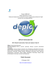
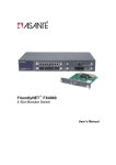
1
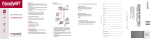
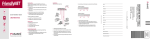
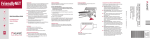
FriendlyNET® FM2008/2009
SNMP/Web Managed Switches
Setup Guide
2
Setup Guide
Quick Start Guide
Follow these steps to install your switch:
1.
2.
3.
4.
5.
Open the box and check the contents. See Chapter 1 for a complete
list of the items included with your switch.
Install the switch in an equipment or wall rack, or prepare it for
desktop placement.
Connect the power supply.
Connect network devices to the switch.
Refer to the User’s Manual on the accompanying CD-ROM for
configuration and management capabilities.
For more information on installing the switch, please refer to Chapter 2.
FriendlyNET FM2008/2009 SNMP/Web Managed Switches
3
4
Setup Guide
Table of Contents
Quick Start Guide
3
Chapter 1 Introduction
Chapter 2 Installation and Setup
7
13
Appendix A Troubleshooting
Appendix B Safety and Regulatory Compliance
Appendix C Specifications
Appendix D Warranty Statement
21
23
25
27
FriendlyNET FM2008/2009 SNMP/Web Managed Switches
5
6
Setup Guide
Chapter 1 Introduction
In today’s society, communication and sharing information are
essential to our lifestyle. Computer networks have proven to be one
of the fastest methods of communication.
The FM2008/2009 switches are compact desktop-sized switches
that are an ideal solution for the SOHO (Small Office or Home Office) network user. They provide a full wire-speed, Fast Ethernet
switching function that allows a high-performance, low-cost connection. Each switch features store-and-forward switching and can
auto-learn and store source addresses on an 8K-entry MAC address table.
The switches provide 8 switched, auto-sensing 10/100 Mbps RJ-45
Ethernet ports. Each switch will automatically detect the speed of
the device(s) connected to it, allowing the use of both 10 and
100Mbps legacy devices. The 10Mbps bandwidth will accommodate
10Mbps workgroup hubs while simultaneously providing the
100Mbps bandwidth needed to accommodate multimedia applications. In addition, each RJ-45 port supports Auto MDI/MDIX function.
The FM2009 switch also provides one 100Base-FX fiber port. Four
types of fiber connectors are available: SC, MT-RJ, VF-45 (multimode), and SC (single-mode). The fiber port can be used to connect to a remote site up to 2 kilometers (multi-mode) or 15–60 kilometers (SC single-mode) away.
With its built-in Web-based Management, managing and configuring the switch is easy: From cabinet management to port-level control and monitoring, you can visually configure and manage your
FriendlyNET FM2008/2009 SNMP/Web Managed Switches
7
network via your web browser. Just click your mouse instead of typing command strings. However, the switch can also be managed via
Telnet, Console, or SNMP Management.
Features
•
•
•
•
•
•
•
•
•
•
•
Conforms to IEEE 802.3, 802.3u, and 802.3x Ethernet Standards
8x auto-sensing 10/100Mbps Ethernet RJ-45 ports
Automatic MDI/MDIX crossover for each 10BaseT/100BaseTX
port
FM2009 only: 1 fixed 100Mbps fiber port (SC/SC single-mode/
MT-RJ/VF-45 connector)
Half-duplex mode for backpressure, and full-duplex for flow
control
Store-and-forward switching architecture for abnormal packet
filtering
Automatic address learning, address migration
8K-entry MAC address table
2Mbit memory buffer sharing
Performs non-blocking full wire speed LED-indicators for
Power, 100Mbps, Link/Activity, Full Duplex
10-inch desktop-sized design
Please refer to the User’s Manual (CD-ROM) for a more complete
list of management features.
Package Contents
Unpack the contents of the switch and verify them against the
following checklist:
•
•
•
•
•
•
8
Switch
Power Cord
Rack Mount Kit
Four Rubber Feet
RS-232 Cable
Setup Guide (this document)
Setup Guide
•
User’s Manual on CD-ROM
Management Methods
The switch series supports the following management methods:
•
•
•
Console and Telnet Management
Web-based Management
SNMP Network Management
Console and Telnet Management
Console Management is done through the RS-232 Console Port.
Managing the switch in this method requires a direct connection
between the computer and the switch, while Telnet management is
done over the network. Once the switch is on the network, you can
use Telnet to log in and change the configuration.
Note: The default IP address of the switch is 192.168.0.1, and the
default user name AND password is root.
Web-based Management
The switch provides an embedded HTML web site residing in flash
memory. It offers advanced management features and allows users
to manage the switch from anywhere on the network through a
standard browser such as Microsoft Internet Explorer.
SNMP Network Management
SNMP (Simple Network Management Protocol) provides a means
to monitor and control network device, and to manage configurations, statistic collection, performance, and security.
FriendlyNET FM2008/2009 SNMP/Web Managed Switches
9
Front Panel
Note: The model shown is the FM2009. The FM2008 is identical,
except that there is no fiber uplink port.
The front panel of the switch consists of 8 auto-sensing
10/100Mbps Ethernet RJ-45 ports (automatic MDI/MDIX), one
100Base-FX fiber port, and the LED indicators.
Four types of fiber connectors are available for the fiber port: SC,
SC single-mode, MT-RJ, and VF-45.
LED Indicators
The fiber port has two LED indicators (Link/Activity, Full Duplex),
and each UTP port has three LED indicators (100Mbps, Link/
Activity, Full Duplex).
The following table provides descriptions of the LEDs’ statuses and
meanings. These LEDs provide a real-time indication of systematic
operation status.
10
Setup Guide
LED
Status
Color
Description
Power
On
Green
Power is on
Off
Power is off
100Mbps
(UTP ports
only)
On
Green
Link/Activity
On
Green
A valid link has been established on the port
Blinking
Green
The port is transmitting or receiving data
Off
The port is operating at 10Mbps or no link has
been established on the port
Off
Full Duplex
The port is operating at 100Mbps
No link has been established on the port
On
Yellow
The port is operating in full-duplex. The fiber
port LED is always on, as auto-negotiation is
disabled on the fiber port.
Blinking
Yellow
Packet collision is detected on the port
Off
The port is in half-duplex mode, or no link has
been established on the port
Rear Panel
The console port and 3-pronged power plug are located at the rear
panel of the switch as shown below. The switch will work with AC in
the ranges 100–240V AC, 50–60Hz.
Console Port: Console management can be done through the console port. It requires a direct connection between the switch and an
end station (PC) via an RS-232 cable. The console port settings are
9600-N-8-1.
FriendlyNET FM2008/2009 SNMP/Web Managed Switches
11
12
Setup Guide
Chapter 2 Installation and Setup
This chapter explains how to install and connect the switch to
your network. To configure the switch for management, refer to
the User’s Manual on the CD-ROM.
The following guidelines will help you prepare to install the
switch in such a way that it has the proper power supply and
environment.
2.1 Safety Overview
The following information provides safety guidelines to ensure your
safety and to protect the switch from damage.
Note: Be aware, however, that this information is intended as a
guideline, and may not include every possible hazard to which you
may be exposed. Use caution when installing this switch.
•
•
•
•
•
Only trained and qualified personnel should be allowed to install or replace this equipment
Always use caution when lifting heavy equipment
Keep the chassis clean
Keep tools and chassis components off the floor and away from
foot traffic
Avoid wearing rings or chains (or other jewelry) that could get
caught in the chassis. Metal objects can heat up and cause
serious injury to persons and damage to the equipment. Avoid
wearing loose clothing, such as ties or loose sleeves
When working with electricity, follow these guidelines:
•
•
•
Before accessing the interior of the chassis, locate
the emergency power-off switch for the room you
are in
Disconnect all external cables before installing or removing a
chassis
Do not work alone when working with electricity
FriendlyNET FM2008/2009 SNMP/Web Managed Switches
13
•
•
•
Always check that the power has been disconnected from the
circuit
Do not tamper with the internal components of your switch.
This could void your warranty
Examine your work area for potential hazards (such as wet
floors or ungrounded cables) and eliminate them before installing your switch
2.2 Recommended Installation Tools
You will need the following tools and equipment (not included) to
install the switch:
•
•
•
Flat head screwdriver
Phillips head screwdriver
Antistatic mat or foam
2.3 Power Requirements
The electrical outlet should be located near the switch and be easily
accessible. It must also be properly grounded.
Make sure the power source adheres to the following guidelines:
•
•
Power: Auto-switching 110/240 VAC
Frequency range: 50/60 Hz
2.4 Environmental Requirements
The switch must be installed in a clean, dry, dust-free area
with adequate air circulation to maintain the following environmental limits:
•
•
14
Operating Temperature: 0° to 40° C (32° to 104° F)
Relative Humidity: 10% to 90% non-condensing
Setup Guide
Failure to observe these limits may cause damage to the switch and
void the warranty.
Avoid direct sunlight, heat sources, or areas with high levels of
electromagnetic interference.
2.5 Installation Overview
Follow these steps to install the switch:
1.
2.
3.
4.
5.
Open the box and check the contents. See Chapter 1 for a complete
list of the items included with your purchase.
Install the switch chassis in an equipment rack or wall rack, or
prepare it for desktop placement.
Connect the power supply.
Connect network devices to the switch.
Refer to the User’s Manual on the CD-ROM for configuring the
switch for management capabilities.
2.6 Chassis Installation/Placement
The switch can be installed in a standard 19-inch equipment rack. It
can also be placed on a stable horizontal surface.
Note: The equipment rack or desk on which you install the switch
must be secure and stable. Equipment racks must be fastened to
the floor; desks must be resting on a flat, stable surface.
2.6.1 Installation in an Equipment Rack
Important! Before continuing, disconnect all cables from the
switch.
To mount the switch into an equipment rack:
1.
2.
3.
Place the switch on a flat, stable surface.
Locate a rack-mounting bracket (supplied) and place it over the
mounting holes on one side of the switch.
Use the screws (supplied) to secure the bracket (with a Phillips
screwdriver).
FriendlyNET FM2008/2009 SNMP/Web Managed Switches
15
4.
5.
6.
Repeat the two previous steps on the other side of the switch.
Place the switch in the equipment rack.
Secure the switch by securing its mounting brackets onto the
equipment rack.
Important! Make sure the switch is supported until all of the mounting screws for each bracket are secured to the equipment rack. Failure to do so could cause the switch to fall, which may result in personal injury or damage to the switch.
2.6.2 Equipment Rack Guidelines
•
•
•
Size: 10.0 x 5.2 x 1.5 inches (254 x 132 x 38 mm)
Ventilation: Ensure that the rack is installed in a room in
which the temperature remains below 40° C (104° F). Be
sure that no obstructions, such as other equipment or cables, block airflow to or from the vents
Clearance: In addition to providing clearance for ventilation, ensure that adequate clearance for servicing the switch from the
front exists
2.6.3 Free-Standing/Desktop Placement
The switch has rubber feet for the bottom of the case that allow for
secure, free-standing placement of the switch.
Follow the steps below for free-standing/desktop placement:
1.
2.
3.
Attach the rubber pads (supplied) to the bottom of each corner
of the switch.
Place the switch on a flat, stable surface.
Make sure enough ventilation space between the switch and
surrounding walls or objects exists.
2.7 Connecting Power
Important! Carefully review the power requirements (Chapter 2.3)
before connecting power to the switch.
Use the following procedure to connect power to the switch:
16
Setup Guide
1.
2.
Plug one end of the supplied power cord into the power connector on the back of the switch.
Plug the other end into a grounded AC outlet. The power LED
will begin its initialization process.
The front panel LEDs blink and the power LED illuminates when it
has initialized. The switch is ready for connection to the network.
Important: If the power does not come on, refer to Appendix A
Troubleshooting.
2.8 Connecting to the Network
The switch may be connected to an Ethernet network with the unit
powered on or off. Use the following procedure to make your network connections:
1.
2.
Connect network devices to the switch, using the cable guidelines that follow.
After the switch is connected to the network, it can be configured for management capabilities. Please refer to the User’s
Manual on the CD-ROM for instructions on how to set up the
management features of the switch.
2.8.1 10/100BaseTX Ports Cabling Procedures
The 10/100 ports on the switch allow for the connection of 10BaseT
or 100BaseTX network devices. The ports are compatible with IEEE
802.3 and 802.3u standards.
Important: The switch must be located within 100 meters of its attached devices.
Note: This switch has no uplink port. All 10/100 ports on this switch
are auto-sensing MDI/MDI-X. This advanced feature means that the
10/100 ports will automatically determine
whether the device at the other end of the link
is a hub, switch, or workstation, and adjust its
signals accordingly.
FriendlyNET FM2008/2009 SNMP/Web Managed Switches
17
Although 10BaseT requires only pins 1, 2, 3, and 6, Asanté strongly
recommends cables with all 8 pins wired as shown in the following
table.
2.8.2 Fiber Cabling Procedures
A fiber multi-mode connector (SC, MT-RJ, or VF-45 connector)
must use 50/125 or 62.5/125 um multi-mode fiber cable. You can
connect two devices over a 2-kilometer distance. However, a fiber
single-mode connector (SC single-mode connector) must use 9/125
BR
WH/BR
GR
WH/BL
BL
WH/GR
OR
WH/OR
18
Pin Number
Pair Number & Wire Colors
1
2 White/Orange
2
2 Orange/White
3
3 White/Green
4
1 Blue/White
5
1 White/Blue
6
3 Green/White
7
4 White/Brown
8
4 Brown/White
Setup Guide
um single-mode fiber cable. With single-mode, you can connect two
devices over a 15–60-kilometer distance in full-duplex operation.
Please refer to the User’s Manual (CD-ROM) for information on how
to configure and manage the switch.
FriendlyNET FM2008/2009 SNMP/Web Managed Switches
19
20
Setup Guide
Appendix A Troubleshooting
In the unlikely event that your network does not operate properly,
follow the troubleshooting tips below:
1.
2.
3.
CHECK YOUR POWER CONNECTION. Is the Power LED on?
If not, plug the power cord into another known working AC outlet.
CHECK YOUR NETWORK CABLES. Are the LINK LEDs on? If
not, check the cable connections. Are the connectors seated
correctly in each port? Make sure that the correct type of cable
is connected to each port.
CHECK YOUR FIBER CONNECTORS. Are the cables inserted correctly? The receiving and transmitting plugs must be
inserted into their respective receptacles correctly in order to
establish a link.
See the Troubleshooting section of the User’s Manual (CD-ROM)
for more detailed information.
FriendlyNET FM2008/2009 SNMP/Web Managed Switches
21
22
Setup Guide
Appendix B Safety and Regulatory Compliance
FCC Compliance Statement
This equipment has been tested and found to comply with the limits
for a Class A digital device, pursuant to part 15 of the FCC Rules.
These limits are designed to provide reasonable protection against
harmful interference when the equipment is operated in a commercial environment. This equipment generates, uses, and can radiate
radio frequency energy and, if not installed and used in accordance
with the User’s Manual, may cause harmful interference to radio
communications. Operation of this equipment in a residential area is
likely to cause harmful interference, in which case the user will be
required to correct the interference at their own expense.
Safety Advisory
1.
2.
3.
4.
This product should be operated from the type of power source
indicated on the marking label. If you are not sure of the type of
power available, consult your dealer or local power company.
Do not allow anything to rest on the power cord. Do not locate
this product where people will walk on the cord.
Never push objects of any kind into this product through cabinet slots as they may touch dangerous voltage points or short
out parts, resulting in a risk of fire or electric shock. Never spill
liquid of any kind on the product.
Do not attempt to service this product yourself, as opening or
removing covers may expose you to dangerous voltage points
or other risks. Refer all servicing to service personnel.
FriendlyNET FM2008/2009 SNMP/Web Managed Switches
23
24
Setup Guide
Appendix C Specifications
See the User’s Manual (CD-ROM) for detailed specifications.
Physical Dimensions
10.0 x 5.2 x 1.5 inches (254 x 132 x 38 mm)
Environmental
Operating Temperature:
Operating Humidity:
0 to 40º C (32 to 104º F)
10 to 90% RH
Power
100-240VAC, 50-60Hz
Power Consumption
17 Watts (max.)
Safety and Emissions Certification
FCC Class A, CE Class A, UL, cUL
FriendlyNET FM2008/2009 SNMP/Web Managed Switches
25
26
Setup Guide
Appendix D. Warranty Statement
Subject to the following limitations and exclusions, Asanté warrants
to the original end user purchaser that the covered products will be
free from defects in title, materials, and manufacturing workmanship
for a period of two years from the date of purchase. This warranty
excludes fans, power supplies, non-integrated software, and accessories. Asanté warrants that the fans and power supplies will be
free from defects in title, materials, and manufacturing workmanship
for two years from date of purchase. Asanté warrants that nonintegrated software included with its products will be free from defects in title, materials, and workmanship for a period of 90 days
from date of purchase, and the company will support such software
for the purpose for which it was intended for a period of 90 days
from the date of purchase. This warranty expressly excludes problems arising due to compatibility with other vendors’ products, or
future compatibility due to third party software or driver updates.
To take advantage of this warranty, you must contact Asanté for a
return materials authorization (RMA) number. The RMA number
must be clearly written on the outside of the returned package.
Product must be sent to Asanté postage paid. In the event of a defect, Asanté will repair or replace defective product or components
with new, refurbished, or equivalent product or components as
deemed appropriate by Asanté. The foregoing is your sole remedy,
and Asanté's only obligation, with respect to any defect or nonconformity. Asanté makes no warranty with respect to accessories
(including but not limited to cables, brackets, and fasteners) included with the covered product, nor to any discontinued product,
i.e., product purchased more than thirty days after Asanté has removed such product from its price list or discontinued shipments of
such product.
This warranty is exclusive and is limited to the original end user purchaser only. This warranty shall not apply to secondhand products
or to products that have been subjected to abuse, misuse, abnormal
electrical or environmental conditions, or any condition other than
what can be considered normal use.
ASANTÉ MAKES NO OTHER WARRANTIES, EXPRESS, IMPLIED, OR OTHERWISE, REGARDING THE ASANTÉ PRODUCTS. EXCEPT TO THE EXTENT PROHIBITED BY APPLICA-
FriendlyNET FM2008/2009 SNMP/Web Managed Switches
27
BLE LAW ALL WARRANTIES OR CONDITIONS OF MERCHANTABILITY OR FITNESS FOR A PARTICULAR PURPOSE
ARE HEREBY DISCLAIMED. ASANTÉ'S LIABILITY ARISING
FROM OR RELATING TO THE PURCHASE, USE OR INABILITY
TO USE THE PRODUCTS IS LIMITED TO A REFUND OF THE
PURCHASE PRICE PAID. IN NO EVENT WILL ASANTÉ BE LIABLE FOR INDIRECT, SPECIAL, INCIDENTAL, OR CONSEQUENTIAL DAMAGES FOR THE BREACH OF ANY EXPRESS
OR IMPLIED WARRANTY, INCLUDING ECONOMIC LOSS, DAMAGE TO PROPERTY AND, TO THE EXTENT PERMITTED BY
LAW, DAMAGES FOR PERSONAL INJURY, HOWEVER
CAUSED AND ON ANY THEORY OF LIABILITY (INCLUDING
NEGLIGENCE). THESE LIMITATIONS SHALL APPLY EVEN IF
ASANTÉ HAS BEEN ADVISED OF THE POSSIBILITY OF SUCH
DAMAGES OR IF THIS WARRANTY IS FOUND TO FAIL OF ITS
ESSENTIAL PURPOSE.
Some jurisdictions do not allow the exclusion or limitation of incidental or consequential damages or limitations on how long an implied
warranty lasts, so the previous limitations or exclusions may not
apply to you. This warranty gives you specific legal rights, and you
may have other rights, which vary from jurisdiction to jurisdiction.
Technical Support
Before contacting Technical Support, please register your switch
online at www.asante.com/support/registration.html, or by returning
the warranty card (found on pages 29 and 30) by mail. In doing so,
you’ll be entitled to special offers, up-to-date information, and important product bulletins.
If, after attempting the troubleshooting tips found here and in the
User’s Manual, your switch is still not operating properly, contact
Asanté Technologies, Inc. Technical Support (801-566-8991 or
[email protected]).
28
Setup Guide
FriendlyNET FM2008/2009 SNMP/Web Managed Switches
29
30
Setup Guide
FriendlyNET FM2008/2009 SNMP/Web Managed Switches
31
FriendlyNET FM2008/2009 SNMP/Web Managed Switches
Setup Guide
Asanté Technologies, Inc.
821 Fox Lane
San Jose, CA 95131
USA
SALES
800-662-9686 Home/Office Solutions
800-303-9121 Enterprise Solutions
408-435-8388
[email protected]
TECHNICAL SUPPORT
801-566-8991 Worldwide
801-566-3787 FAX
www.asante.com
[email protected]
Copyright © 2002 Asanté Technologies, Inc. Asanté and FriendlyNET are registered trademarks of
Asanté Technologies, Inc. The Asanté logo is a trademark of Asanté Technologies, Inc. All other
names or marks are trademarks or registered trademarks of their respective owners. All features
and specifications are subject to change without prior notice.
P/N 06-00674-00 Rev. A 11/18/02