1
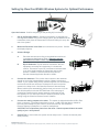
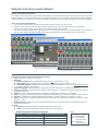
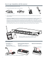
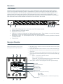
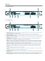
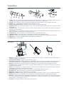
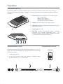
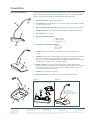
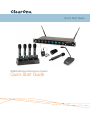
Quick Start Guide
WS800 Wireless Microphone System
Quick Start Guide
Setting Up ClearOne WS800 Wireless Systems for Optimal Performance
Open the Cartons: Confirm everything on the packing slip is enclosed.
1.
Set up the Docking Station: ClearOne transmitters are shipped with rechargeable batteries. Plug in the charging dock, put the batteries in the transmitters, then place the transmitters in the dock while you set up the rest of the system.
2. Mount the Receivers in the Rack and connect them to power. Confirm the displays light up.
3.
Antenna Design:
A.
Place the antennas according to the guidelines mentioned in the Antenna Applications Guide. Improper antenna placement is the main cause of poor RF performance.
B.
Dipole Antennas: Dipole antennas mounted to the rack equipment can easily be locked away in a closet/rack cabinet. This results in poor RF performance because there is no line of sight between the transmitter and receiver antenna. Therefore, remote antennas are preferred.
See the Antenna Application Guide for details.
4.
Connect the Antennas: The receiver that connects to the antennas should be set as the Antenna Master receiver. Master is the factory default. If your system daisy-chains antennas together, the downstream Master
receivers should be set as Slaves. Terminators are used on the last system in the daisy-chain. Use ClearOne Remote’s Antenna Setup Wizard, which opens automatically the first time you connect. You can
also find the wizard under the SETTINGS tab of the main page. If Terminators
Slave
connecting ClearOne active remote antennas, make sure the red LED lights up. If not, check the receiver’s antenna phantom power
setting using the ClearOne Remote Control Software.
5. Connect the analog outputs to the mixer: The system is shipped with either XLR or Euro block connectors. The default output level is set to +4 dBu. Note that factory default for the front panel headphone jack is set for mixed line-level out. Use ClearOne Remote>Settings>Headphone, to reset for headphones.
CAUTION! Turn off phantom power from the mixer. Phantom power distorts the audio quality of your microphones.
6. System Test: In most cases, the system is now ready to use. Confirm all channels pass audio perfectly.
Modifications (FCC 15.21)
Changes or modifications to this equipment not expressly approved by ClearOne may void the user’s authority to operate this equipment.
2
Using the ClearOne remote software:
Editing Transmitter Parameters:
The easiest and most intuitive way to set the parameters of ClearOne transmitters and receivers is with ClearOne
Remote software. Load ClearOne Remote from the disk provided onto a computer running Windows XP or Windows
7 (32 or 64-bit) and connect to the receiver via USB or RS232. Then open ClearOne Remote and select ONLINE.
Open The Channel Edit Window:
1. The [Click to Edit] function opens the edit window of the channel you wish to edit.
2. Select the functions you want to edit and enter the parameter. (The various functions are described below.) Click [OK] to save the changes and close the Channel Edit window.
3. You will notice that the [Needs to Sync] alert is lit. This indicates that one or more parameters are in queue in
the receiver ready to be downloaded and implemented with the next transmitter Sync of the channel.
1) Click to Edit the channel’s parameters
2) Select the new parameter values and
click OK to save changes to the receiver.
3) The “Need To Sync” alert is lit. Sync the transmitter
to apply the selected parameters.
ClearOne Remote provides the following functions:
1. File: Save a PDF image of the screen.
2. Settings:
A. Phantom Power: Turn antenna phantom power on or off. Default = ON.
B. Redundancy: Set adjacent pairs of receivers to redundancy mode. Default = OFF.
C. Headphone Mode: Toggles the mixed output jack from headphone mode to a balanced line output.
Default = Balanced line output.
3. Ethernet Settings: If using Ethernet, assign the proper IP address to the ClearOne Receiver.
4. RF Scan - RF Plot: Shows the RF strength of each antenna in a ClearOne system and shows if there is
outside interference.
5. Presets: Save or load preset system parameters configurations. Default = As Ordered.
6. GPIO: Assign contact closure functions and setup for RS232 control. Default = RS232 - Output mutes.
7. Security: Password to prevent unauthorized changes: (Under construction). Default = none.
8. Alerts: Send alerts to authorized personal when preventive maintenance is required of if there is a fault.
Default = none.
9. Update System: Checks to see if the system has the most current firmware and provides a wizard for
updating the firmware.
10.Help:
A. Tutorials: Setting parameters, Antenna Application Guide, etc.
B. About: Shows vital statistics for each component of the system
Default Transmitter Preamp Gain Settings:
Transmitter + Last 4 digits of serial Number
3
Default Transmitter Preamp Gain
BLT XXXX
10 dB
HH XXXX
H18 = 0dB / H10 = 10dB
PDM XXXX
10dB
BDM XXXX
20dB
Key:
BLT = Beltpack
HH = Handheld Mic
PDM = Gooseneck
/Podium Mic
BDM = Tabletop
Boundary Mic
How to sync transmitters with the receiver:
How to sync transmitters with the receiver:
1. Locate the IR (infrared) Sensor on the transmitter.
IR
IR
IR
IR
IR
IR
ON/OFF
USB
USB
ON / OFF
2. Power on the transmitter.
3. Hold transmitter about 6 inches from the corresponding receiver module with the IR sensor aimed at the
receiver module.
4. Simultaneously press the two buttons on the bottom of the corresponding receiver module to start sending
the IR signal. “SYNCING” shows on the receiver OLED when the IR signal starts. “SYNC OK” shows
when the sync is successful. Repeat the procedure if the receiver display shows “SYNC FAILED”. It is not
necessary to press any buttons on the transmitter during the procedure. Note: You may get a “Sync Failed”
message if the receiver antennas are not in the same room as the receiver. In this case verify that either the
transmitter display shows “Sync Good” OR the green LED on the transmitter flashes. Also make sure to dock
each transmitter after syncing to avoid 2 transmitters being synced to the same receiver frequency.
NOTE: The transmitter and receiver are assigned a new,
random AES 256-bit encryption key every time they are synced.
How to read the LED:
1. The Gooseneck or
Boundary Mic is in use:
RED = AUDIO MUTE
GREEN = AUDIO PASSES
BLINKING RED = BATTERY IS LOW
BLINKING GREEN = SYNC SUCCESSFUL
2. The Gooseneck Battery Cassette and Boundary Mic are in the docking station:
RED = CHARGING
OFF/OR GREEN = FINISHED CHARGING
BLINKING RED = CHARGING ERROR (RE-SEAT THE
TRANSMITTER AND CHECK THE BATTERIES)
NOTE: All transmitters placed in the charging dock will “RF MUTE”.
4
3. When the Hand-held Mic and the Belt-pack are in the Docking Station:
The OLED shows
the battery status
Receiver:
FRONT PANNEL:
ClearOne receiver main-frames hold either four or eight, independent, 24-bit digital audio receiver modules.
There is a front-panel mixed audio output for headphones or direct recording. Each module shares the mainframe’s two antennas for full-diversity. Up to eight receiver main-frames can be daisy-chained together into an
antenna network that shares two antennas. This eliminates the need for external antenna distribution amps.
Main-frames can be connected to form an Ethernet network that monitor and control the system via a computer.
Main-frames also have USB and RS232 connections for serial monitor and control.
Made In USA
USB
POWER
PHONES
1
3
2
4
5
6
1.
2.
3.
4.
Antenna Front Mounting Hole: Use back-to-front TNC cables included.
Receiver Module. See details below
Mixed audio volume control.
USB Port. Connect to computer for ClearOne Remote control. Run software to monitor/edit system
parameters, scan for RF interference and download firmware upgrades.
5. Mixed audio output, 1/4” (See headphone mode - Pg. 3) phone jack for monitoring individual channels
or mixed channels.
6. Power Switch.
Receiver Module:
MODULE:
Modules are designed for quick and easy
field replacement for added redundancy.
1
2
3
IR
SELECT
1
2
AUDIO
BATTERY
SLOT 3
ON
CH 1
AES256
1.
Select Next Function: Move the cursor to the next menu function on the display
(Under construction)
2. IR Sync LED: Sends IR information to SYNC the receiver and transmitter (SYNC pg4)
3. Select Previous Function: Move the cursor to the previous menu function (Under
construction)
4. Soft Key Left: Select the choice displayed in the bottom left of the display 4 & 6
pressed at the same time: Sends SYNC signal from receiver to transmitter (SYNC pg4)
5. Status LED:
•
Green --> The channel is ON and un-muted
•
Red --> The channel is OFF
•
Flashing Red --> Encryption key mismatch, Re-sync receiver with transmitter
•
Amber --> The receiver is muted or GPIO is triggered
6. Soft Key Right: Select the choice displayed in the bottom right of the display
RF BARS
ANTENNA DIVERISITY
AUDIO LEVEL
BATTERY LEVEL
CHANNEL NAME
ENCRYPTION
STATUS: (Colored text indicates status)
ON = Green
OFF = Red
MUTE = Amber
KEY = Flashing Red (“KEY” = mismatched encryption key)
FUNCTION
(SYNC)
STATUS
FREQUENCY
5
4
5
6
Receiver:
BACK PANEL WS880:
7
1
Made In USA
IN
IN
-
8
+
G
-
7
+
G
-
6
+
G
-
5
+
-
G
4
+
G
-
3
+
G
-
2
+
G
-
1
+
G
OUT
OUT
50-60 Hz 100-240 VAC
ANTENNA B
2
3
ETHERNET
4
RS232-GPIO
5
ANTENNA A
MIC OUTPUTS
6
8
BACK PANEL WS840:
7
1
Made In USA
IN
IN
-
4
+
G
-
3
+
G
-
OUT
ANTENNA B
2
2
+
G
-
1
+
G
OUT
50-60 Hz 100-240 VAC
3
ETHERNET
4
RS232-GPIO
5
MIC OUTPUTS
6
ANTENNA A
8
1. Antenna A Input: TNC connector for dipole antennas (included), front-to-back antenna cables (included), or
antenna cable to active extension antenna.
2. Antenna A Output: Daisy-chain to the input of another receiver-frame to form an antenna network.
3. Power Cord Input: (Cord with local plug configuration Included). 100-240 VAC, 50/60Hz, 15 W, 250V 320mA
slow-blow fuse (spare included)
4. Ethernet: Connect to a computer or network. Multiple receiver-frames can be daisy-chained together to form
a network. (Under construction)
5. GPIO/RS232: This connector combines a General Purpose Input / Output (GPIO) and a RS232 on one
DB25 connector. The RS232 can be disabled to add up to 24 GPIO pins.
RS232: The pinout for the RS232 is the standard pinout. Pin 2 on the receiver is transmit, pin 3 is receive,
and pin 7 is ground. Most computers now use a DB9 connector for RS232. The standard off-the-shelf DB9
to DB25 cable will work. This cable swaps pins 2 and 3 internally. If you computer has a DB25 connector for
RS232, use a straight DB25 to DB25 cable. Do not use a null modem cable.
GPIO: GPIO acts like a contact closure. Use ClearOne Remote to assign an event that toggles the GPIO
pin. The factory default toggles pins X through X to correspond to muting a receiver module. ClearOne
Remote has a feature that lets you assign how the system responds to a transmitter mute (see ClearOne
Remote)
A. Mute the channel’s receiver audio. (Factory default)
B. Toggle the GPIO but do not mute the receiver audio. Use this with automated mixers or echo cancelling
DSPs.
C. Mute the channels receiver audio and toggle the GIPO pin.
6. Audio Output Jacks: Configured for four or eight-module receiver frames and for XLR or Euro-block terminal
connectors.
7. Antenna B Input: TNC connector for dipole antennas (included), front-to-back antenna cables (included), or
antenna cable to active extension antenna (see section on antennas, antenna placement and antenna cables).
8. Antenna B Output: Daisy-chain to the input of another receiver-frame to form an antenna network.
6
Transmitters:
HAND-HELD:
6
8
6
9
8
9
7
1
3
2
4
4
10
11
12
1.Heads: Five (5) microphone condenser elements are available. In general, condenser heads are more
“transparent” and do not require the microphone to be held as close to the mouth.
2.Display: OLED display is used to program and display the current status of the transmitter functions.
3.Switch: User programmable to toggle on/off, on/mute/ or on/on.
4. Battery and Control Cover: Unscrew counter-clockwise and gently slide open.
5. Antenna Cover: Do not hold the antenna cover. Your hand will shield the RF signal and cause poor audio
performance.
6. IR Sensor Port: The IR sensor is used to transfer channel settings and a random encryption key from the
receiver to the transmitter.
7. Select button: Press this button to select a function. The first press activates the first edit able function in the
tree. Press again to move to the next edit able function.
8. Parameter Up: Press this button to increase the value of the selected function.
9. Parameter Down: Press this button to decrease the value for the selected function.
10.USB Port: Plug a micro USB cable into the USB port to charge the batteries or upgrade the firmware.
11.Batteries: (not shown) AA NiMH, 2200 to 2500-mAHr recommended.
12.Battery Door: Open position.
5 6 7 8
BELT PACK:
s
2
1
3
4
9
11
10
12
13
13
10
1. Antenna: Length and style varies with the transmitters model number. Antennas are field replaceable to
improve reliability and redundancy.
2. Programmable Switch: Toggle on/off, on/mute/ or on/on.
3. Microphone Connector: TA4 mini XLR style: ClearOne offers a full range of lavaliere and headset mics for
optimal performance of your ClearOne transmitter. Works with both snap in and screw-in microphones.
4. Display: OLED display is used to program and display the current status of the transmitter functions.
5. IR Sensor Port: The IR sensor is used to transfer channel settings and a random encryption key from the
receiver to the transmitter.
6. Select: Press this button to select a function. The first press activates the first edit able function in the tree.
Press again to move to the next edit able function.
7. Parameter Down: Press this button to decrease the value for the selected function.
8. Parameter Up: Press this button to increase the value of the selected function.
9. Batteries: AA NiMH, 2200 to 2500-mAHr recommended.
10. Battery Door Locks: To open, press both at the same time and lift the door open. To close, snap the door closed.
11. USB Port: Plug a micro USB cable into the USB port to charge the batteries or upgrade the firmware.
12. Belt-Clip: Spring-loaded clip for attaching the transmitter to a belt or similar object. Spring pressure presses
the clip into two holes in the transmitter body. Pull them out to remove or reverse the clip. Exercise caution to
prevent injury or scratching the case.
13. Contacts: Charging contact points for the docking station.
7
Transmitters:
CONFERENCE TABLE-TOP:
The ClearOne DS80-C Conference Table-top Mic combines the professional audio specs and security of a
wired mic with wireless convenience. Available in omni or cardioid polar pick-up patterns with 265-bit FIPS 197
encryption.
1.
Power LED: When the Table Mic is on, the LED signals:
Red = audio mute
Green = audio passes
Blinking Red = battery low
Blinking Green = sync successful.
2. Contacts: Contact points for the charging station.
3. I/R Sensor: Inputs programming instructions and encryption
key from the receiver.
4. Power Switch: On / Off.
1
5. USB Port: Doubles as the power supply / recharger
connection and computer programming port.
The
transmitter operates normally under USB power, with dead
or no batteries for permanent installations.
2
IR
OFF/ON
USB
3
4
5
2
PODIUM GOOSENECK STEM :
GOOSENECK MIC CAPSULE:
ClearOne Gooseneck Podium Mic Stems are available in 18” and 12”
lengths that are interchangeable and the Gooseneck mic comes with
cardioid polar pattern.
1.
CARDIOID
Flexible stem section.
2. A 4-pin XLR connector allows the exchange of different length
microphone stems (12, 18, inch lengths).
3
2
2
1
8
Transmitters:
PODIUM GOOSENECK:
The ClearOne Podium microphone combines the professional audio specs
and security of a wired mic with wireless convenience. For use with battery
power or permanently install the microphone using USB power.
1. ClearOne Capsules: Cardioid polar pattern.
1
2
2. Goosenecks: Two flexible sections to extend over a laptop or briefcase. Available
in 12 and 18 inch lengths.
3. Radio-transparent ABS Top: Stylish design that hides and protects the antenna.
4. Cast Metal Bottom: Zinc base bottom adds stability and absorbs desk noise.
3
5. Power LED: (see fig. 2 below)
6. Button Programming Options:
1) press to talk
2) press to mute
3) toggle on or off.
7. Power Switch Programming Options:
1) On / Off
2) On / Mute
3) On / On.
4
8. I/R Sensor: Inputs programming instructions and encryption key from the
receiver.
9. USB Port: Doubles as the USB recharger connection and computer programming
port. The transmitter operates normally under USB power, with dead or no
batteries for permanent installations. When charging using the USB Port, The LED
signals: RED = Charging / OFF = finished charging.
5
6
10. Battery Cassette: Push tab to remove the battery cassette. Recharge the
batteries by inserting the cassette into the ClearOne Charging Dock. (See figure 1)
The battery cassette holds four, off-the-shelf, AA, NiMH batteries for up to 9.5
hours continuous usage per charge.
11. Keyholes: For permanent mounting
12. Rubber Feet: Absorb desk noise and provide a stable, non-skid base.
(Figure 1)
(Figure 2)
Recharge the batteries by inserting the
cassette into the ClearOne Charging Dock.
9
When the Gooseneck Mic is in use, the LED signals:
8
7
RED = Audio Mute
GREEN = Audio Passes
BLINKING RED = Battery Low
BLINKING GREEN = Sync Successful
12
11
9
10
North America
Tel: 801-975-7200
Toll Free: 800-945-7730
Sales: 800-707-6994
Fax: 801-977-0087
[email protected]
Europe & Oceania
Tel: +44 (0) 1189 036 053
[email protected]
Asia Pacific
Tel: +852 3590 4526
[email protected]
Latin America
Tel: 801-974-3621
[email protected]
Middle East
Tel: +852 3590 4526
[email protected]
Other product names may be registered trademarks of their respective owners who do not necessarily endorse ClearOne or ClearOne’s products. All rights reserved. Information in
this document subject to change without notice. © 2012 ClearOne. QSG-0007-001 Revision 1.0 December 2012.