1
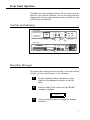
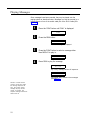
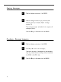
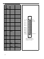
Lucent Technologies
Bell Labs Innovations
Multiple Digital Message Unit
Installation and Use Manual
Issue 1, October 1999
© 1999 Bogen Communications, Inc.
All rights reserved. 54-2024-01 9910
Model: LUMDMU
PEC Code: 5325-100
COM Code: 408184000
Select Code: 701-000-117
© 1999 Bogen Communications, Inc.
All Rights Reserved. Printed in U.S.A.
Repairs to this equipment, other than routine repairs, can be
made only by the manufacturer or its authorized agents.
Notice
If the equipment causes harm to the telephone network, the
local telephone company may temporarily discontinue your
service and, if possible, notify you in advance. If advance notice
is not practical, you will be notified as soon as possible. You will
be given the opportunity to correct the problem and informed
of your right to file a complaint with the FCC.
Every effort was made to ensure that the information in this
guide was complete and accurate at the time of printing.
However, information is subject to change.
FCC Statement (Part 15) - Radio Frequency
Interference
The Multiple Digital Message Unit generates and uses radio
frequency energy and if not installed and used in strict accordance with the manufacturer's instructions, may cause interference to radio and television reception. Testing is being conducted for compliance with the limits for a Class B device in
accordance with the specifications in Part 15 of the FCC Rules
and Canadian D.O.C. regulations. This testing is designed to
provide reasonable protection against such interference.
However, there is no quarantees that interference will not
occur in a particular installation. If this equipment does cause
interference to radio or television reception, which can be
determined by turning the Multiple Digital Message Unit off
and on, the user is encouraged to try to correct the interference by one or more of the following measures:
- Reorient the radio or TV receiving antenna.
- Relocate the Multiple Digital Message Unit with respect to
the radio or TV receiver or vice-versa.
- Plug the Multiple Digital Message Unit unit into a different
outlet so that it and the radio or TV receiver are on different
branch circuits.
If necessary, the user should consult the dealer or an experienced radio/television technician for additional suggestions. The
user may find the following booklet. "How To Identify and
Resolve Radio-TV Interference Problems," helpful. This booklet
was prepared by the Federal Coommunications Commission
(FCC) and is available from the U.S. Government Printing
Office, Washington, DC 20402. Stock order No. 004-00000345-4.
Federal Communications Commission (FCC)
Statement (Part 68)
This equipment is component registered with the Federal
Communications Commission (FCC) in accordance with Part
68 of its rules. In compliance with the rules, be advised of the
following:
Registered eqipment may not be used with Coin Telephone
Lines. Equipment may be used with Party Lines in areas where
state tariffs permit such connections and when equipment is
adaptable for such service.
This equipment is registered as follows:
Registration Number - F4PCAN-20988-AN-N
Ringer Equivalence -1.6B
If trouble is experienced, the equipment should be disconnected from the interface to determine if this equipment, or the
telephone line is the trouble source. If the equipment is determined to be malfunctioning, it should not be reconnected until
repairs are effected.
The local telephone company may make changes in its facilities,
operations, or procedures that could affect the proper functioning of your equipment. If they do, you will be given adequate notice in writing to allow you an opportunity to maintain uninterrupted telephone service.
Important Safety Information
Always follow these basic safety precautions when installing
and using the system:
1. Read and understand all instructions.
2. Follow all warnings and instructions marked on the products.
3. DO NOT block or cover the ventilation slots and openings.
They prevent the product from overheating. DO NOT place
the product in a separate enclosure or cabinet, unless proper
ventilation is provided.
4. Never spill liquid on the product or drop objects into the
ventilation slots and openings. Doing so may result in serious
damage to the components.
5. Repair or service must be performed by a factory authorized repair facility.
6. The product is provided with a CSA approved, 3-wire
ground type plug. This is a safety feature. DO NOT defeat the
safety purpose of the grounding type plug. DO NOT staple or
otherwise attach the AC power supply cord to building surfaces.
7. DO NOT use the product near water or in a wet or damp
place (such as a wet basement).
8. DO NOT use extension cords. The product must be
installed within 6 feet of a grounded outlet receptacle.
9. DO NOT install telephone wiring during a lightning storm.
10. DO NOT install telephone jacks in a wet location unless
the jack is specifically designed for wet locations.
11. Never touch uninsulated wires or terminals, unless the line
has been disconnected at the paging or controller interface.
12. Use caution when installing or modifying paging or control
lines.
Support Information
Paging systems integrated with small phone systems such as
Merlin Legend and Partner are supported by the National
Service Assistance Center (NSAC). The main number for the
NSAC is 800-628-2888. Paging systems integrated with large
switches such as the DEFINITY G3 are supported by the
Technical Service Center (TSC). The main number for the TSC
is 800-242-2121.
Domestic and International Approvals
CSA Certified LR55025;NRTL/C Certified: FCC Part 15 and
Part 68.
Table of Contents
Introduction
1
Before You Start
1
Installation Steps
2
Power Up System
6
Front Panel Operation
7
■ Controls and Indicators
7
■ Recording Messages
7
■ Listening to Recorded Messages
9
■ Playing Messages
10
■ Playing Messages in Sequence
11
■ Adding a Time Delay Between Message Plays
12
■ Clearing a Message Sequence
13
■ Checking Message Times
14
■ Reset Delay Times to Default
15
■ Audio and Memory Tests
Audio Test
Memory Test
15
15
16
Telephone Access Operation
17
■ Recording Messages
17
■ Listening to Recorded Messages
17
■ Playing Messages
18
■ Clearing a Message Sequence
18
Specifications
19
iii
Introduction
The Multiple Digital Messaging Unit (MDMU) is a micro processor based
digital voice announcement system. It outputs prerecorded messages
through a public address system. Up to 99 messages can be placed in
the units digital memory for queued replay. Up to eight messages can
be programmed to play in sequence with timed delays.
Depending on the amount of memory option configured in the MDMU,
multiple messages can range from 32 seconds up to 8 minutes 44
seconds in length. Voice and audio messages can be stored into
memory through dial-up telephone, microphone interface, or tape input.
(The MDMU is programmed by dial-up telephone DTMF tones.)
This guide gives installation, recording, and programming steps. Since
messages are digitally stored, and there are no moving parts, the MDMU
should give years of uninterrupted service.
Before You Start
Before installing your system, read and understand the safety instructions
on page ii. Be sure you have all the necessary parts, tools, and test
equipment, listed below.
■
■
■
■
1
Read important Safety Information on Page ii.
2
Check Shipping Container Contents.
Multiple Digital Messaging Unit
Mounting Hardware (screws and brackets)
Cables, RJ-21 to wire lug end and power cord
This Installation and Configuration guide
1
3
Have Required Tools
The following tools are required for the installation of the MDMU
hardware an cabling.
■
Phillips screwdriver (small and large)
■
Standard blade screwdriver (small and large)
■
Wire strippers (24 AWG - 12 AWG)
■
Telephone test set
■
Tone out circuit tester (optional, for troubleshooting)
■
Volt-ohm Meter (optional for troubleshooting)
■
4 wood screws, if mounted on wall
Installation Steps
1
Mount the MDMU to either a wall, cabinet or a rack
(near the paging equipment if possible).
Figure 1. Wall Mounted Unit
2
Figure 2. Rack Mounted MDMU
2
Connect the MDMU to the Telephone System
AUX. CONNECTOR
J1
REM
OPTION
SWITCH
BATTERY
OFF ON
MOST
TELEPHONE
SYSTEM
TIP AND RING FROM
ANALOG STATION
Figure 3 MDMU Connection to Telephone System
3
3
Plug the modular cord into connector J1 on MDMU
and connect the wires on the other end to the
Over Ride terminal.
Figure 4. MDMU Connection to Over Ride
4
NOTE: For specific pin-out
information for this connector
refer to Figure 9 at the end of
this guide. Messages 1
through 6 correspond to
message starts 1 through 6.
Connect the RJ-21 cable/connector to the MDMU Aux.
Interface and to terminal block.
AUX. CONNECTOR
J1
REM
OPTION
SWITCH
BATTERY
OFF ON
RJ-21 CABLE AND
CONNECTOR
SCREW LUG
TERMINAL BLOCK
MESSAGE #1
TYPICAL CONNECTION
TO MOMENTARY
CONTACT CLOSURE
TO START MESSAGE
TYPICAL
CONNECTION TO
TERMINAL BLOCK
MESSAGE #6
Figure 5 Connection of RJ-21 Cable to MDMU.
4
5
NOTE: Switches 1, 2, and 3
sets the number of messages in
a single queue sequence. The
timing between those
messages is set by switches 4,
5, and 6. Switch 7 sets the
total possible number of
messages for the unit. Switch
8 is always in the ON position.
REM
Set the MDMU options on the DIP switch. Refer to
the table below.
BATTERY
OFF ON
OPTION
SWITCH
Figure 6 Set MDMU Options on DIP Switch
Table 1. DIP Switch Setting Definitions
SET
SET
SET
SET
SET
SET
SWITCH SWITCH SWITCH SWITCH SWITCH SWITCH
# 2 TO
# 7 TO
# 3 TO
# 5 TO
# 6 TO
# 4 TO
MAX. No. of
MESSAGES IN
SEQUENCE:
SET
SWITCH
# 1 TO
1
ON
ON
ON
—
—
—
—
2
OFF
ON
ON
—
—
—
—
3
ON
OFF
ON
—
—
—
—
4
OFF
OFF
ON
—
—
—
—
5
ON
ON
OFF
—
—
—
—
6
OFF
ON
OFF
—
—
—
—
7
ON
OFF
OFF
—
—
—
—
8
OFF
OFF
OFF
—
—
—
—
DEFAULT DELAY BETWEEN MESSAGES:
0:05
—
—
—
ON
ON
ON
—
0:10
—
—
—
OFF
ON
ON
—
0:30
—
—
—
ON
OFF
ON
—
1:00
—
—
—
OFF
OFF
ON
—
5:00
—
—
—
ON
ON
OFF
—
15:00
—
—
—
OFF
ON
OFF
—
30:00
—
—
—
OFF
OFF
OFF
—
—
—
—
—
ON
OFF
NUMBER OF MESSAGES AVAILABLE:
1 TO 9
01 TO 99
—
—
5
Power Up System
1
Plug the power cord into the A.C. input connector on
the MDMU, then into the wall oulet.
The MDMU will display three messages in sequence:
MDMU 2.00
Software version of unit.
3.16
Total time available in memory for
recording.
IDLE
Indicates the status MDMU: Idle = no
activity; PLY = A message is being
played out through connector J1; Delay =
the time delay between successive
messages is active.
2
NOTE: The internal battery
maintains the recorded
messages two hours in the
event of a power failure or
brownout. Allow 48 hours to
fully charge.
If power is to be removed from
the MDMU for an extended
period of time, turn the battery
switch to the Off position to
avoid permanent damage to
the battery.
NOTE: The suggested reliable
lifetime of the rechargeable
battery used in the equipment
is 36 months. To ensure the
system has reliable battery
backup, it is recommended
the battery be replaced every
30 months.
6
Push the Battery slide switch to the ON position.
The MDMU is now ready to record and play meassages.
REM
Figure 7 Battery Switch
OPTION
SWITCH
BATTERY
OFF ON
Front Panel Operation
The MDMU can record messages input from the front panel through the
Hand Set, Tape, and Mic connectors. The unit also record and store
messages input remotely through telephone access to the REM port using
a DTMF (touch tone) telephone.
Controls and Indicators
FRONT VIEW
FUNC
MULTIPLE DIGITAL
MESSAGING UNIT
HAND
SET
RUN
TAPE
MIC
TAPE
INPUT
MIC
INPUT
IDLE
FUNCTION
DISPLAY
RUN
FUNCTION
BUTTON
FUNCTION
SELECTION
BUTTON
HANDSET
INPUT
REAR VIEW
AUX. CONNECTOR
50 PIN RJ-21
CONNECTOR
J1
MESSAGE
OUTPUT
REM
TELEPHONE
ACCESS
OPTION
SWITCH
BATTERY
OFF ON
OPTION
SWITCH
BATTERY
SWITCH
POWER
INPUT
Figure 8 Controls and Indicators.
Recording Messages
The highest priority message should be recorded on the lowest message
number (1) to ensure fastest replay (i.e. Fire in Building...).
1
2
Plug the telephone handset, microphone, or tape
player into the appropriate connector on the front
panel.
Press the (black) FUNC button until the RECORD
message is displayed.
RECORD
3
Press the (red) RUN button to display the message
number #1.
7
NOTE: Depending on number
of messages optioned during
installation (switch 7), the
(available message numbers
will read 1 through 9, or 01
through 99.
4
5
NOTE: If the message number
selected has been
pre-recorded, a messaged will
display "SURE?" Press "RUN"
again to append to the existing
message.
To record on another message number, press the
FUNC key until the desired message number appears.
Press the RUN button and begin speaking into the
handset, microphone, or press play on the tape player.
SURE ?
During recording, the display
will show the amount of
memory remaining for the unit
in minutes and seconds.
mm:ss
6
When recording is complete, press the FUNC key.
The display shows the amount of time
used for the message:
NOTE: While recording a
message, pressing RUN will
pause the recording. Press
RUN again to continue.
TIME
0:30
DONE
IDLE
7
8
Repeat steps 2 through 6 to record other messages.
Listening to Recorded Messages
1
NOTE: Use the front panel
handset to listen to messages.
Press the FUNC button until the display indicates
monitor.
MONITOR
2
Press the RUN button to select the message number.
MSG-01
3
Press the FUNC key until the desired message
number appears.
MSG-11
4
As the message plays into the
handset, the display counts
down the message time.
Press RUN to listen to the message.
mm:ss
Length of message.
DONE
Done playing message.
9
Playing Messages
Once messages have been recorded, they may be played over the
paging system as described below. Messages can also be queued by a
contact closure of one of the switch cable pair of the RJ-21 cable (See
figure 5).
1
Press the FUNC button until PLAY is displayed.
PLAY
2
Press the RUN button.
MSG-01
The first message is displayed.
3
Press the FUNC button to select a message other
than MSG-01 to play in.
MSG-09
4
Press RUN to play the message.
PLY-S09
Ply = Play, message #9 out off sequence.
DEL-S09
Configured delay between the messages
(see table 1).
NOTE: If a contact closure
comes in on the RJ-21 cable,
the message sequence will
stop. The contact closure
message will play until the
closure is removed. The
sequence message will resume
where it left off.
10
Playing Messages in Sequence
A group or sequence of messages can be played to the output channel.
The maximum number of messages in a sequence can be up to 8
(determined by the DIP switch settings on the back panel). To add
messages to the sequence simply repeat the PLAY command, selecting
the message to be added each time.
1
Press the FUNC button until PLAY is displayed.
PLAY
2
Press the RUN button.
MSG-01
The first message is displayed.
3
Press the FUNC button to select a message other
than MSG-01 to play in:
MSG-09
4
Press RUN to play (and group) the message.
PLY-S09
Ply = Play, S = sequence message #9.
5
Repeat steps 1 through 4 to add up to 8 messages if
you are configured for 8 (see page 9).
NOTE: If a contact closure
comes in on the RJ-21 cable,
the message sequence will
stop. The contact closure
message will play until the
closure is removed. The
sequence message will resume
where it left off.
11
Adding a Time Delay Between Message Plays
A time delay can be inserted before successive message plays. The
amount of time depends on the maximum time delay set on the option
DIP switch.
1
Press the FUNC button until DELAY appears.
DELAY
2
Press the RUN button to display the message
numbers.
MSG-01
3
NOTE: A delay may only be
selected for a message which
has previously been recorded.
Press the FUNC button to select the message number
to add the delay.
MSG-04
4
Press the RUN button to display the delay times.
DLY-0:05
5
Press the FUNC button to scroll the available delay
times.
DLY-0:30
30 second delay
6
Press the RUN button to accept the selected delay time.
DONE
7
12
Repeat steps 1 through 6 to add delays to other
message numbers.
Clearing a Message Sequence
The message sequence can be cleared leaving the
individual messages to be played separately.
1
Press the FUNC button until PLAY is displayed
PLAY
2
Press the RUN button.
MSG-01
3
Press the FUNC button until the following message is
displayed.
MSG-00
This is the message abort number.
4
Press RUN to clear the message sequence.
CLEARED
DONE
IDLE
13
Checking Message Times
The TIME function displays the time used for each message recorded.
It also displays the remaining time available in system memory to record
other messages.
1
Press the FUNC button until TIME appears.
TIME
2
Press the RUN button (once) to view message
numbers and recording time.
MSG-01
Message number.
mm:ss
Time used to record message in
minutes and seconds.
3
Once all messages and times are displayed, the
display indicates:
LEFT
Amount of time left on the system to
record other messages.
2:09
Available MDMU memory time in minutes
and seconds.
DONE
14
Reset Delay Times to Default
The INIT (initialize) function resets the operating parameters and delay
time to the default setting of five seconds without effecting the recorded
messages.
1
Press the FUNC button until INIT appears.
INIT
2
Press the RUN button.
SURE ?
Verification of command.
3
Press the RUN button again to initialize.
WAIT
DONE
Audio and Memory Tests
Two diagnostics tests are built into the MDMU internal software. The
audio test plays a 1000 Hz tone to the installed J1 output line. The
memory test clears all recorded messages and internally writes and
reads a number of test patterns to verify proper operation.
Audio Test
1
Press the FUNC button until TEST appears.
TEST
2
Press the RUN button to display the test options.
AUD TEST
3
Press the RUN button again to begin the test.
15
4
Press the FUNC button to end the continuous audio
test.
WAIT
IDLE
Memory Test
1
Press the FUNC button until TEST appears.
TEST
2
Press the RUN button to display the test options.
AUD TEST
3
Press the FUNC button to select the memory test.
MEM TEST
4
Press the RUN button to initialize the test.
SURE ?
Verification of memory test command.
CAUTION! The memory test
will erase all recorded and
stored messages.
5
Press the Run button again to begin the test.
ADD TEST
To cancel the memory test
command, press the FUNC
button.
0
This number indicates the number of times
the memory test has executed.
6
Press the FUNC button to end the test.
DONE
16
Telephone Access Operation
The MDMU may be accessed remotely using a DTMF (Touch Tone)
telephone. Telephone access can be made directly through a telephone
switching system with one of its analog stations connected to the MDMU
REM port.
Recording Messages
1
2
3
4
Dial the telephone extension of the MDMU.
Press ✽ 7 (R for record) and the message number.
(for example, ✽ 76 - record message number 6)
When you hear the beep, begin recording the
message.
Optionally, to send this message to a particular
paging zone, dial the zone number
now, then continue recording this message.
5
Press the # keys to end recording and save message.
6
Press the # key again to disconnect from the MDMU.
Listening to Recorded Messages
1
2
Dial the telephone extension of the MDMU.
Press ✽ 6 (M for monitor) and the message number.
(for example, ✽ 609 - monitor message number 9)
Press the # key to end monitoring message.
Press the # key again to disconnect from the MDMU.
17
Playing Messages
1
2
Dial the telephone extension of the MDMU.
Dial the message number to play over the public
address system (for example, 14, for message
number 14).
The message is played and added to the sequence of
messages playing.
Press the # key to disconnect from the MDMU.
Clearing a Message Sequence
1
Dial the telephone extension of the MDMU.
2
Press 0 (or 00 if set for 99 messages).
This action removes all messages from the sequence,
stops any contact closure message starts, and places
the MDMU in the IDLE state.
3
18
Press the # key to disconnect from the MDMU.
Specifications
Table 2 lists the specifications for the Multiple Digital Messaging Unit.
Figure 9 on the next page give the Aux. Connector pin-out definitions.
Table 2 Multiple Digital Messaging Unit Specifications.
Power Supply
■
Dimensions and
Weight
■
■
■
■
Fuse Ratings
■
■
115 VAC, 60 Hz, or 220 VAC, 50 Hz (specified on MDMU rear panel).
Height: 1.75 inches (4.4 cm).
Width: 16.25 inches (41cm) without brackets, 19 inches (48.3 cm) with brackets attached.
Depth: 9.25 inches (23.5 cm).
Weight: 13 pounds (6 kg).
AC Power: MDL 0.25 amp Slow Blo.
Battery: MDL 2.0 amp Slow Blo.
Temperature
Range:
■
■
0 to +40 deg. C. (32 to 104 deg. F.) operational.
–40 to +66 deg. C. (–40 to +150 deg. F.) storage and shipment.
Humidity Range:
■
5% to 95% (non-condensing) storage/shipment and operation.
Altitude:
■
Sea level to 10,000 ft. operational (1048 to 648 millibars) 40,000 ft. max. shipment.
Environmental
■
Locate in an area free of excess moisture, corrosive gases, dust, and chemicals.
Battery Backup
■
Allows up to two hours of operation during a power failure. Total charge time 48 hours.
Frequency
Response
■
– 200 Hz to 3.4 kHz ( +3 dB).
Output Level
■
Adjustable to a maximum of –9 dBm.
Input Impedance
■
Handset: 220 ohm; Microphone: 600 ohms; Tape: 10K ohms.
Voice Encoding
■
8 KHz sampling rate, 8 bits/sample (PCM).
Interconnect
Cable
■
50 pin, RJ-21 connector providing contact closure message starts.
19
PIN
1
2
3
4
5
6
WIRE COLORS
BLUE
WHITE
ORANGE
WHITE
GREEN
WHITE
BROWN
WHITE
SLATE
WHITE
BLUE
RED
7
8
9
10
11
12
13
14
15
16
17
18
19
20
21
22
23
24
ORANGE
GREEN
BROWN
SLATE
BLUE
ORANGE
GREEN
BROWN
SLATE
BLUE
ORANGE
GREEN
BROWN
SLATE
BLUE
ORANGE
GREEN
BROWN
SLATE
WHITE
WHITE
WHITE
WHITE
25
26
27
28
29
30
31
32
33
34
35
36
37
38
39
40
41
42
43
44
45
46
47
48
49
50
WHITE
RED
RED
RED
RED
RED
BLACK
BLACK
BLACK
BLACK
BLACK
YELLOW
YELLOW
YELLOW
YELLOW
YELLOW
VIOLET
VIOLET
VIOLET
VIOLET
VIOLET
Table 3
20
RED
RED
RED
RED
BLACK
BLACK
BLACK
BLACK
BLACK
YELLOW
YELLOW
YELLOW
YELLOW
YELLOW
VIOLET
VIOLET
VIOLET
VIOLET
VIOLET
BLUE
ORANGE
GREEN
BROWN
SLATE
BLUE
ORANGE
GREEN
BROWN
SLATE
BLUE
ORANGE
GREEN
BROWN
SLATE
BLUE
ORANGE
GREEN
BROWN
SLATE
BLUE
ORANGE
GREEN
BROWN
SLATE
DEFINITION
J1 RING
CP 1 (C)
CP 1 (NC)
CP 1 (NO)
TIP 1
START 1 ( – )
START 1 ( + )
START 2 ( – )
START 2 ( + )
START 3 ( – )
START 3 ( + )
RING REMOTE
J1 TIP
START 1 ( – )
START 1 ( + )
START 2 ( – )
START 2 ( + )
START 4 ( – )
START 4 ( + )
ALARM ( NC )
START 5 ( – )
START 5 ( + )
ALARM ( NO )
START 6 ( – )
START 6 ( – )
ALARM ( C )
TIP REMOTE
26
27
28
29
30
31
32
33
34
35
36
37
38
39
40
41
42
43
44
45
46
47
48
49
50
1
2
3
4
5
6
7
8
9
10
11
12
13
14
15
16
17
18
19
20
21
22
23
24
25
RING 1
CP 1 ( C )
CP 1 ( NC )
CP 1 ( NO )
RING REMOTE
START 3 ( – )
START 3 ( + )
NOTE: The alarm contact
points are used for monitoring
the MDMU for unit failure.
START 4 ( – )
START 4 ( + )
ALARM (NC)
START 5 ( – )
START 5 ( + )
ALARM (NO)
START 6 ( – )
START 6 ( + )
ALARM ( C )
TIP REMOTE
Figure 9
50 Pin Connector and Wiring Code.