1
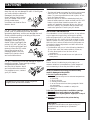
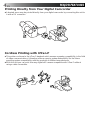
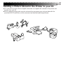
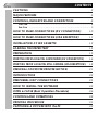
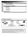
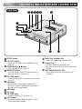
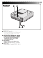
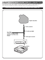
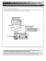
DIGITAL VIDEO PRINTER
GV-DT1
ENGLISH
Please visit our CyberCam Homepage on
the World Wide Web and answer our Consumer Survey (in English only):
http://www.jvc-victor.co.jp/index-e.html
INSTRUCTIONS
LYT0119-001A
EN
EN
SAFETY
PRECAUTIONS
WARNING:
TO PREVENT FIRE OR SHOCK
HAZARD, DO NOT EXPOSE
THIS UNIT TO RAIN OR
MOISTURE.
CAUTION
n When you are not using the unit for a long
period of time, it is recommended that you
disconnect the power cord from the mains
outlet.
n Dangerous voltage inside. Refer internal
servicing to qualified service personnel. To
prevent electric shock or fire hazard, remove
the power cord from the mains outlet prior to
connecting or disconnecting any signal lead
or aerial.
The STANDBY/ON
button does not
completely shut off mains power to the unit, but
switches operating current on and off. " "
shows electrical power standby and " " shows
ON.
The mains outlet shall be installed near the unit
and shall be easily accessble.
NOTE:
The rating plate (serial number plate) and safety
caution are on the bottom and/or the back of the main
unit.
IMPORTANT (for U. K. owners)
Connection to the mains supply in the United
Kingdom.
DO NOT cut off the mains plug from this
equipment. If the plug fitted is not suitable for
the power points in your home or the cable is
too short to reach a power point, then obtain a
proper safety approved extension lead/adapter
or consult your dealer.
BE SURE to replace the fuse only with an
identical approved type, as originally fitted,
and to replace the fuse cover.
If nonetheless the mains plug is cut off remove
the fuse and dispose of the plug immediately,
to avoid a possible shock hazard by inadvertent connection to the mains supply.
If this product is not supplied fitted with a
mains plug then follow the instructions given
below:
DO NOT make any connection to the Larger
Terminal coded E or Green.
The wires in the mains lead are coloured in
accordance with the following code:
Blue to N (Neutral) or
Black
Brown to L (Live) or
Red
If these colours do not correspond with the
terminal identifications of your plug, connect
as follows:
Blue wire to terminal coded N (Neutral) or
coloured Black.
Brown wire to terminal coded L (Live) or
coloured Red.
If in doubt — consult a competent electrician.
1
2
EN
Some Do's And Don'ts On The Safe
Use Of Equipment
This equipment has been designed and manufactured to meet international safety standards
but, like any electrical equipment, care must be taken if you are to obtain the best results and
safety is to be assured.
DO read the operating instructions before you attempt to use the equipment.
DO ensure that all electrical connections (including the mains plug, extension leads and
interconnections between pieces of equipment) are properly made and in accordance with
the manufacturer's instructions. Switch off and withdraw the mains plug when making or
changing connections.
DO consult your dealer if you are ever in doubt about the installation, operation or safety of
your equipment.
DO be careful with glass panels or doors on equipment.
DON'T continue to operate the equipment if you are in any doubt about it working normally,
DON'T
DON'T
DON'T
DON'T
DON'T
DON'T
DON'T
or if it is damaged in any way — switch off, withdraw the mains plug and consult your
dealer.
remove any fixed cover as this may expose dangerous voltages.
leave equipment switched on when it is unattended unless it is specifically stated that it
is designed for unattended operation or has a standby mode. Switch off using the
switch on the equipment and make sure that your family knows how to do this. Special
arrangements may need to be made for infirm or handicapped people.
use equipment such as personal stereos or radios so that you are distracted from the
requirements of road safety. It is illegal to watch television whilst driving.
listen to headphones at high volume, as such use can permanently damage your
hearing.
obstruct the ventilation of the equipment, for example with curtains or soft furnishings.
Overheating will cause damage and shorten the life of the equipment.
use makeshift stands and NEVER fix legs with wood screws — to ensure complete
safety always fit the manufacturer's approved stand or legs with the fixings provided
according to the instructions.
allow electrical equipment to be exposed to rain or moisture.
ABOVE ALL...
— NEVER let anyone especially children push anything into holes, slots or any other
opening in the case — this could result in a fatal electrical shock;
— NEVER guess or take chances with electrical equipment of any kind — it is better to be
safe than sorry!
CAUTIONS
Exercise caution when moving the printer. If you
drop the unit, do not attempt to use it. If during use
you notice that the cabinet is
damaged, shut the printer
down, unplug it and contact
your JVC dealer. Use of the
printer under these
conditions can lead to fire or
electric shock.
DO NOT place heavy objects on the printer’s
power cord, or leave the cord near any heatgenerating appliance, as this can damage the cord.
Avoid excessive pulling or twisting of the power
cord. If the power cord
becomes cut or otherwise
damaged, contact your JVC
dealer. When unplugging the
printer, DO NOT pull on the
cord. Hold the plug itself and
remove it from the AC outlet.
Use of the printer with a
damaged power cord can
lead to fire, electric shock
and unit malfunctions.
DO NOT remove the cover and attempt to repair or
modify the printer. There are high-voltage
components within the unit,
and the risk of electric shock
and unit malfunctions exists.
If a problem occurs, contact
your JVC dealer.
Illustrations of this video printer maydiffer
slightly from production models.
EN
3
ABOUT THERMAL HEADS
• The thermal heads, necessary for printing, are located
within the unit. The heads can become extremely
warm. To prevent possible burns and injuries, do not
touch the thermal heads.
• When the printer is used for extended periods, the
thermal heads experience wear and tear just like VCR
heads. As the thermal heads become worn, print
quality will gradually decrease. When you notice a
decline in quality, it is possible that the heads may
need to be replaced. Consult your JVC dealer.
MOISTURE CONDENSATION
If condensation occurs inside the printer, it may adhere
to print paper during printing, causing poor quality
prints and paper jams. If you think condensation may
exist within the unit, let the unit sit for at least 2 hours
(with the power on) to dry sufficiently. If paper is stuck
within the unit, remove it before turning the power on.
Unused print paper subjected to moisture should not
be used for printing.
• Condensation may occur in the following situations:
1) In a room when the heater suddenly comes on;
2) In the direct path of cool air from an air
conditioner;
3) When the unit is moved from a cool place to a
warm place.
DUST
Due to dust or lint adhering to print paper, or to
extreme variations in temperature, a small degree of
colour smearing or lines may be visible in prints.
Failure to heed the following precautions may
result in damage to the printer.
1. DO NOT place the printer . . .
... in an environment prone to extreme temperatures
or humidity.
... in direct sunlight.
... in a dusty environment.
... in an environment where strong magnetic fields
are generated.
... on a surface that is unstable or subject to
vibration.
2. DO NOT block the printer’s ventilation openings.
3. DO NOT place heavy objects on the printer.
4. DO NOT place anything which might spill on top of
the printer.
5. AVOID violent shocks to the printer during
transport.
CAUTION:
Changes or modifications not approved by JVC
could void user’s authority to operate the
equipment.
4
EN
MAJOR FEATURES
Printing Directly from Your Digital Camcorder
● A desired scene may be printed directly from your digital camcorder by connecting this unit to
it with a DV connector.
Cordless Printing with IrTran-P
● This printer conforms to the IrTran-P standard which ensures a greater compatibility in the field
of video communications. It therefore offers a superior system extendibility for the future
providing system compatibility with the products of different manufacturers.
● With this unit you can print from any digital still camera compatible with IrTran-P without
using a cable connection.
EN
Sending a Picture Stored in the Printer to your PC
● You can store a picture from a digital camcorder or a digital still camera in the printer and
transfer it to your PC.
● More creative printing work may be achieved by processing your picture data with the
provided MGI PhotoSuite or other commercially available painting software.
5
6
CONTENTS
EN
CAUTIONS
3
MAJOR FEATURES
4
CONTROLS, INDICATORS AND CONNECTORS
8
Front View ....................................................................................... 8
Rear View ....................................................................................... 9
HOW TO MAKE CONNECTIONS (DV CONNECTION)
10
HOW TO MAKE CONNECTIONS (IrDA RECEPTION)
11
INSTALLATION OF INK CASSETTE
12
LOADING THE PAPER TRAY
14
PREPARATION
15
PRINTING FROM A DIGITAL CAMCORDER (DV CONNECTION)
16
PRINTING FROM A DIGITAL STILL CAMERA (IrDA RECEPTION)
18
PERSONAL COMPUTER PRINTER SECTION
21
INTRODUCTION
22
PERIPHERAL UNIT CONNECTIONS
24
HOW TO INSTALL THE SOFTWARE
25
OPEN & CLOSE (Basic Operation Procedure)
26
CONTROLS AND OPERATIONS
28
PRINTING PROCEDURE
31
CAPTURING A PICTURE INTO the PC
32
EN
PRINTING FROM the PC
7
33
How the Setup Dialog Works .............................................................. 34
How the Spooler Window Works ......................................................... 35
INDICATIONS AND MESSAGES
36
Lamp Indications .............................................................................
Printer Section ...............................................................................
PC Printer Section ............................................................................
Other Problems: .............................................................................
When Paper Jams ...........................................................................
SPECIFICATIONS
36
39
40
42
43
44
PROVIDED ACCESSORIES
CD-ROM
Floppy Disk
•MGI PhotoSuite
Paper Tray
Blank Paper Sheet Set
•Standard Print Paper (10 sheets)
•Ink Cassette (10 prints)
DV cable
• It should be noted that it may be unlawful to print from pre-recorded tapes or discs without
the consent of the owner of copyright in the video recording, broadcast or cable
programme and in any literary, dramatic, musical, or artistic work embodied therein.
• The copyright for the program which provides IrDA infrared communications for this
software is owned by Okaya Systemware Co., Ltd.
IrDA Protocol Stack "Deep Core TM " Okaya Systemware Co., LTD.
8
CONTROLS, INDICATORS AND CONNECTORS
EN
Front View
1 2345
6
7
8
9
0
!
1 PRINT button
2 IrDA/DV button
• Switches the video input between IrDA
and DV.
3 STANDBY/ON button
• Turns the printer on and off.
4 MEMORY button
• Used to store a video picture delivered
through the DV connector.
5 ON LINE button
• Press this for video communications with
your PC.
6 Vent holes
• Periodically clean these holes with a
vacuum cleaner. Make sure the printer’s
power cord is unplugged.
IrDA
lamp
7
DV
lamp
8
9 ON LINE lamp
• Lights when the PC mode is on.
0 IrDA sensor
• Receives a video data through the IrDA
communication system.
@
#
! Paper Tray Insertion Slot
• Insert the paper tray into this slot.
@ Output Tray
• Printed sheets are stacked here.
* Be sure to open the tray when using the
printer.
# Ink Cassette Insertion Slot
• Open this to load or unload the ink
cassette.
EN
Rear View
$ %
^ &
$ PARALLEL Connector
• Connect to the parallel (printer) terminal
of a computer using a commercially
available printer cable.
% Service Door for Jammed Paper Removal
• Open this door when paper is jammed.
* Do not open this door unless paper is
jammed. Be sure to close this after
clearing the paper jam.
DV
connector
^
• Used to receive a video data from a
digital camcorder with a DV connector.
Power
Cord
&
• Plug into an AC outlet (AC 220 – 240 V).
9
10
EN
HOW TO MAKE CONNECTIONS (DV CONNECTION)
Some televisions and video cassette recorders require a specific type of output cable. Refer to
their instruction manuals for details on television and VCR connections to the GV-DT1.
WHEN PRINTING FROM A DIGITAL CAMCORDER WITH A DV CONNECTOR
Digital camcorder
To DV connector
DV cable (provided)
Core Filter
Connect the end provided
with the Core Filter to the
Printer.
To DV input connector
DV IN
Printer
HOW TO MAKE CONNECTIONS (IrDA RECEPTION)
EN
11
WHEN PRINTING FROM AN IrTran-P COMPATIBLE DIGITAL STILL CAMERA
IrTran-P (Infrared Transfer Picture):
An infrared video data communications format which enables infrared communications of
video data between compatible units of different manufacturers.
IrTran-P compatible
digital still camera
Approx. 15°
Approx. 15°
Within an approx.
50 cm distance
Data communications may
not be possible between
some units when they are
too close or too distant.
IrDA sensor
Printer
Video data communications with the IrDA infrared communications system can be
accomplished only between one transmitter and one receiver.
If a picture is sent from one digital still camera to more than one printer, the picture can be
received and printed only by the printer that has first responded to the transmission.
12
INSTALLATION OF INK CASSETTE
EN
1
Install the ink cassette included with the available
blank paper sheet set.OF INK CASSETTE
INSTALLATION
CASSETTE DOOR
1 OPEN
Pull the right top of the door in the direction
indicated by the arrow to open it.
UP SLACK
2 TAKE
Turn the roller on the side with the “
2
in the direction of the arrow.
Do not turn the part marked with
mark
A
” mark
.
INK CASSETTE
3 INSTALL
Insert the cassette label-side up from the end
marked. Push it until you hear a click.
A
3
CASSETTE DOOR
4 CLOSE
Push the right side of the door.
•The door clicks when it is fully closed.
4
Lock lever
When removing ink cassette
Push the lock lever in the direction of arrow.
The ink cassette is unlocked and can be removed.
CAUTION
Do not stick your fingers into the ink cassette
storage space. You may be burned or injured.
EN
13
About Blank Paper Sheet Sets (optional)
You must use one of the sets shown in the following chart:
SET
CONTENTS
PV-50SFAE
(Standard type)
• Standard Print Paper (50 Sheets)
• Ink Cassette (50 Prints)
Print your favorite images, just like
snapshots.
*PV-25SFSAE
• 1-Picture Single-Print Sticker
Paper (15 Sheets)
• 16-Picture Multi-Print Sticker
Paper (10 Sheets)
• Ink Cassette (25 Prints)
Make customized seals and stick
them on greeting cards, envelopes,
letters, etc.
PV-25UFAU
(Super Fine HG
type)
• Standard Print Paper (25 Sheets)
• Ink Cassette (25 Prints)
Suitable for storing Print paper.
(Sticker type)
USES
* This unit does not incorporate a function for splitting the screen into 16 pictures.
Printing on 16-picture multi-print sticker paper is impossible unless the digital still camera or the
application software has a 16-picture splitting function.
When multiple pictures are printed on a sheet, the print positions may vary from the intended
positions.
Before Printing
● Do not touch printing side of the paper.
● Do not use paper that is torn or curled, as
this can result in paper jamming.
● Do not use paper that is wet or damp.
Printing may not be possible and paper
jamming may occur.
● Do not touch or pull out the ink cassette’s
ink sheet.
● Keep young children away from the ink
cassette’s ink sheet.
● When the ink cassette is empty, replace it
with a new one. An empty ink cassette
cannot be used. Do not try to rewind and
re-use cassette.
● Do not expose the paper to high temperatures, high humidity and/or direct sunlight.
● You can write on one side of a PV-50SFAE
print sheet.
● If you want to write something or stick a
stamp on a PV-50SFAE sheet, wait until
printing is finished. If you write something
or stick something on before printing, the
printer may not work properly.
● Carefully read the precautions in the blank
paper sheet set box and on the back of the
blank sheet set before using.
After Printing
● If you touch a fresh print with wet hands,
the print image may be discolored.
● If a print absorbs organic cleaning solvents
(alcohol, ester, keton, etc.), the colours will
fade.
● If cellophane tape or soft PVC are affixed to
a print, the chemical reaction will cause
accelerated colour fading.
● When writing on a PV-50SFAE print sheet,
be sure to use a pencil or an oil-based
writing utensil. If you apply too much
pressure, you’ll leave imprints on the print
sheet.
Storage
● Avoid storing prints in areas subject to high
temperatures or humidity, or near a heater
or heat-generating device.
● Do not store prints in a soft plastic folder.
Accelerated colour fading may result due to
the chemical reaction, or the print(s) may
stick to the file.
● Do not store 2 prints with the printed sides
touching, as the sheets may stick together.
● Store print paper in its box, on a level
surface. Failure to do so may cause the print
paper to curl or bend, which can result in a
paper jam within the unit.
14
LOADING THE PAPER TRAY
EN
Opening the paper tray
A
● Open the lid while pushing
A
.
Inserting blank paper sheets in the
paper tray
To printer
Printing side
Cautions
Partition panel
1. Keep the partition panel upright. If it is
tilted, get it upright by pushing the back of
the paper tray.
2. Load print sheets in the tray, placing the
side with the detection marks toward you,
face down.
•Sticker sheets are not provided with
detection marks. Simply load them so that
the printing side faces upward.
•The tray can hold up to 25 sheets at one
time.
Detection marks
Be sure to read “Precautions when
inserting printing paper” on the back of
the paper tray lid.
Output tray
Loading/unloading the paper tray
● When loading, push the tray until it clicks.
● When unloading, push the tray slightly to
unlock the latch, then pull it out.
PREPARATION
EN
15
● Before printing, make sure everything is set up and ready.
1
Have a Blank Paper Sheet Set ready. (page 13)
2
Install the ink cassette in the printer (page 12)
3
Place the blank paper sheets in the paper tray and load the tray
(page 14).
● Use print sheets and ink cassette from the same kit.
4
Open the output tray.
5
Connect image source to the printer (page 10).
6
Plug the printer’s power cable into an AC outlet and press the
button.
● Power comes on and the
indicator lights.
You are now ready to print. For specific printing instructions,
read the page corresponding to the type of printing you
want to do (pages 16 through 19).
16
EN
PRINTING FROM A DIGITAL CAMCORDER (DV CONNECTION)
Preparation
● See page 10 for connection.
THE CAMCORDER TO PLAY
1 SET
•Refer to the instruction manual of your
camcorder.
IrDA/DV
MEMORY
PRINT
IrDA
ON LINE
DV
THE IrDA/DV BUTTON OF THE
2 PRESS
PRINTER
•When the DV lamp is
Blinking : Video data is being received by
the printer.
Lighting : Video data is not under reception.
Check for proper connection
referring to page 10.
ON LINE
YOU HAVE REACHED THE
3 WHEN
SCENE YOU WANT TO PRINT, SET
THE CAMCORDER TO STILL PICTURE
THE PRINTER MEMORY
4 PRESS
BUTTON
IrDA/DV
MEMORY
PRINT
IrDA
•The picture you want to print is stored in
memory.
•The PRINT lamp is blinking during video
data conversion (for about 40 seconds).
ON LINE
DV
ON LINE
When you want to transmit the stored
picture to your PC, see “Capturing a Picture
into the PC” on page 32.
EN
IrDA/DV
MEMORY
PRINT
IrDA
ON LINE
DV
ON LINE
17
THE PRINT LAMP STOPS
5 WHEN
BLINKING AND LIGHTS,
PRESS THE PRINT BUTTON
•The PRINT lamp blinks and printing starts.
•Printing is finished when the print paper is
discharged with the PRINT lamp lit.
•If you want to print the same picture again,
press the PRINT button again after printing
has once finished. Every pressing of the
PRINT button produces one print copy.
•If you want to print another picture, repeat
the steps 3 to 5.
18
EN
PRINTING FROM A DIGITAL STILL CAMERA (IrDA RECEPTION)
When using a digital still camera compatible with IrTran-P, please refer also to the instruction
manual provided with the camera.
Preparation
When only storing a picture
Remove the paper tray from the printer.
IrDA/DV
MEMORY
PRINT
ON LINE
When storing and printing a picture
Load the paper tray containing print sheets.
When picture data is sent from the digital
still camera, a copy is automatically printed.
THE PRINTER IrDA/DV
1 PRESS
BUTTON TO START THE IrDA
LAMP LIGHTS
THE PICTURE YOU
2 STORE
WANT TO PRINT IN THE DIGITAL STILL CAMERA
IrDA
DV
ON LINE
• Refer to the instruction manual
provided with the camera for details.
THE PICTURE IN THE
3 TRANSMIT
CAMERA TO THE PRINTER
IrDA sensor
• Aim the IrDA transmitter of the digital
still camera at the IrDA sensor of the
printer.
• The picture data is sent from the digital
still camera to the printer.
• Refer to the instruction manuals
provided with the machines in use for
details of their operation.
• The DV and ON LINE lamps blink with
the paper tray removed. Press the ON
LINE button to light the ON LINE lamp,
so as to cancel blinking.
If you want to transmit the stored picture
to your PC, refer to “Capturing a Picture
into the PC” on page 32.
q The picture is automatically
transmitted to the printer. A copy
is then automatically printed.
• When transmission is finished, the IrDA
lamp changes from blinking to lighting.
• Printing is finished when the print
sheets are discharged and the PRINT
lamp lights.
EN
19
q Procedure from Picture Data Transmission to Printing
The picture data sent from the digital still camera is automatically printed. The PRINT lamp
lights and blinks as indicated below until printing is finished.
PRINT
DV
IrDA
ON LINE
DATA BEING TRANSMITTED
1 PICTURE
FROM CAMERA TO PRINTER
Blinking slowly
PRINT
IrDA
DV
ON LINE
Lighting
Blinking
PRINT
IrDA
DV
ON LINE
CONVERTING THE PICTURE
2 PRINTER
DATA AFTER TRANSMISSION
• This may take several minutes depending on
the machines in use or the volume of data
transmission.
CONVERSION FINISHED
3 DATA
• Printing automatically starts with the paper
tray loaded.
Lighting
Blinking slowly
PRINT
IrDA
Lighting
DV
ON LINE
4 PRINTING FINISHED
Lighting
• The picture data is being stored in memory as
long as the PRINT lamp is lit. Every pressing
of the PRINT button produces a print copy of
the same picture.
• When you want to print another picture,
repeat the steps 2 and 3 on the previous page.
• Data communications may be variable or
impossible depending on the lighting
condition, battery consumption,
communications distance and sending and
receiving angles.
20
EN
MEMO
EN
21
PERSONAL COMPUTER
PRINTER SECTION
q The Readme.TXT file provides additional information for setup and information
that is not included in the instruction manual. Please read the file before installing
the provided software program.
q You can find the latest information (in English) on the provided software program
at our www server:
<www>http://www.jvc-victor.co.jp/
q If you want to process the picture, see the Idea Guide of the MGI PhotoSuite
included in the CD-ROM.
22
INTRODUCTION
EN
REQUIRED HARDWARE
qBi-Directional 25-pin printer interface
q486DX2 or higher CPU
OPERATING ENVIRONMENT
qPersonal computer with MicrosoftT* WindowsT* Operating System Version 3.1
(also verified to run with MicrosoftT WindowsT 95)
* MicrosoftT and WindowsT are trademarks of the Microsoft Corporation registered in the
United States and other countries.
q16 MB RAM or more
qAt least 8 MB available hard disk space
qColour display capable of handling at least 640 x 480 dots and 256 colours
(Recommended: true colour 24-bit)
qWindowsT-compatible mouse connected to PC
q3.5” 1.44MB floppy disk drive
qCD-ROM drive
THINGS YOU’LL NEED IN ADDITION THE PROVIDED
ACCESSORIES
A commercially available printer cable (3 m or shorter). Use one capable of all-pin wiring.
Some PCs are compatible only with a particular design of printer cable. Consult your dealer
before purchasing a cable.
When using a printer cable which is over 3 m long, a transmission error may occur.
(Example)
25-pin male
D-sub
36-pin male
Micro ribbon
EN
23
SOFTWARE FEATURES
DRIVER WINDOW
Print orientation, number of prints and image adjustment can be selected in this window.
•Print orientation : Portrait/Landscape
•No. of prints
: 1 to 25
•Image adjustment
Contrast
: Low — High (11 grades from –5 — +5)
Brightness : Dark — Bright (11 grades from –5 — +5)
CAPTURE UTILITY WINDOW FOR IMAGE CAPTURING
Images stored in the GV-DT1 can be processed and stored in your computer in the bitmap
(BMP) format.
Storage
format
File
Extension: *.BMP format
(full colour / 256 tone /
gray scale)
Image size 640 x 480 /
320 x 240 / 160 x 120
Image capture / Save /
Save as / Exit
Edit
Undo / Copy / Rotate 90° /
Resize / Change colour mode
Image
Enlarge / Reduce
Window
Tile / Cascade / Arrange
icons / Select file
Help
Help menu / Version
The GV-DT1 “Driver and capture utility software” is not operable as a network printer.
24
PERIPHERAL UNIT CONNECTIONS
EN
Some televisions and video cassette recorders require a specific type of output cable. Refer to
their instruction manuals for details on television and VCR connections to the GV-DT1.
When Printing from PC
q When connecting components, make sure all units are turned off.
Printer
To
PARALLEL
connector
Commercially
available printer
cable (bidirectional
parallel interface)
Parallel (printer)
connector
HOW TO INSTALL THE SOFTWARE
EN
INSTALLING IN A WINDOWST COMPATIBLE PC
25
See the instruction manual of WindowsT or the PC in use for the basic operation of WindowsT.
In the case of WindowsT 95
In the case of WindowsT 3.1
up WindowsT 95.
1 Start
• If you have any other applications
up WindowsT 3.1.
1 Start
• If you have any other applications
open, close them all.
open, close them all.
the “Driver & Capture Utility
2 Insert
Software” into the floppy disk drive.
the “Driver & Capture Utility
2 Insert
Software” into the floppy disk drive.
the My Computer icon on
3 Double-click
the desktop.
[File Manager] from the [Main]
3 Select
group on the WindowsT display.
a floppy disk drive.
the floppy disk icon.
4 Select
4 Double-click
• The setup. exe file appears on the display.
• The SETUP icon appears on the display.
the SETUP icon.
5 Double-click
• Installation begins.
• Follow the instruction messages on the
display.
• If you agree to the Software Licensing
Agreement, press [Yes]. If not, press
[No], and the processing is closed.
the setup. exe file.
5 Double-click
• Installation begins.
• Follow the instruction messages on the
display.
• If you agree to the Software Licensing
Agreement, press [Yes]. If not, press
[No], and the processing is closed.
the [Reboot] button.
6 Click
• WindowsT is once closed and then
the [Reboot] button.
6 Click
• WindowsT is once closed and then
opened again.
• This completes the installation
procedure.
opened again.
• This completes the installation
procedure.
The provided software is capable of displaying 6 languages including English, German,
French, Spanish, Italian and Dutch.
The language used by the software is selected automatically at the time of installation
according to the language setup of your personal computer.
English is used when your personal computer is set to a language other than one listed
above.
26
EN
OPEN & CLOSE (Basic Operation Procedure)
GETTING STARTED
You can launch this program using the standard procedure for WindowsT. There are some
differences between WindowsT 3.1 and WindowsT 95.
WindowsT 3.1 offers a number of ways to launch an application.
1. Open the group of application icons on the program manger and double-click the application you want to open.
2. Select Run in the program manger, select the file name of the application and click the
RUN button.
3. Double-click the application name in the File Manager menu.
File(F)
Edit(E)
View(V)
Help(H)
With WindowsT 95, click the [START] button on the taskbar, and the program menu
appears on the screen. Move the cursor to the program you want to run and click to start
the program.
Accessories
StartUp
MS-DOS Prompt
Windows Explorer
Now let’s actually launch the program.
If you’re using WindowsT 3.1, open the JVC GV-DT1 Capture group on the program manager
and double-click the JVC GV-DT1 Capture icon.
If you’re using WindowsT 95, select JVC GV-DT1 Capture on the start menu and start it.
EN
27
Once the program has loaded, WindowsT 3.1 displays the screen shown below.
Icon button
Control menu button
File(F)
Edit(E)
Titlebar
Image(I)
Window(W)
Maximize button
Help(H)
The titlebar and menubar look different on WindowsT 95.
Icon button
Control menu button
File(F)
Edit(E)
Titlebar
Image(I)
Window(W)
Close button
Help(H)
Maximize button
CLOSING THE PROGRAM
Double-click the control menu button in WindowsT 3.1 or click Close GV-DT1 Capture Utility
(X) on the [File (F)] menu.
With WindowsT 95, simply click the Close button.
28
CONTROLS AND OPERATIONS
EN
MENUBAR
File(F)
Edit(E)
Image(I)
Window(W)
Help
Capture New(N)
Save(S)
Save As(A)
Exit Capture Utility(X)
The menubar provides several menus with lists of commands that enable you to execute various
program functions.
Click the desired item on the menubar to pull down the menu. Then click on the desired
command in the pulldown menu.
Some commands may not be executable depending on where you are in the program. Disabled
functions look lighter than other items.
Each menu is configured as shown below
File(F)
Capture New(N)
Save(S)
Save As(A)
Exit Capture Utility(X)
Select to capture the image stored in printer into the
computer.
Select to change the file content without changing
the file name. This erases all the content previously
entered.
Select to save as a new file.
Closes the capture utility program.
EN
Edit(E)
Select to undo the most recent work done.
Select to copy to the clipboard. The copy is displayed in
colour according to the monitor setup.
Select to rotate through 90° clockwise.
Select to rotate through 90° counterclockwise.
Select to reduce the captured image to 1/4 or 1/16.
Select to change the number of colours (colour grade scale)
of the capture image.
Undo(Z)
Copy(C)
Rotate 90° Clockwise(9)
Rotate 90° Counterclockwise(0)
Resize(S)
Change Colour Mode(C)
Captured image
File(E)
Edit(E)
Image(I)
Window(W)
Help(H)
29
Rotate 90° clockwise
File(E)
Edit(E)
Image(I)
Window(W)
Rotate 90° counterclockwise
Help(H)
File(E)
Edit(E)
Image(I)
Window(W)
Help(H)
A
A
A
Click Undo when you want to restore the previous image.
Edit(E)
If you want to restore the previous size after resizing, click Undo.
If you resized the image more than once, you cannot restore the
original size.
Undo(Z)
Copy(C)
Rotate 90° Clockwise(9)
Rotate 90° Counterclockwise(0)
Resize(S)
Change Colour Mode(C)
640x480->320x240
640x480->160x120
Captured image
File(E)
Edit(E)
Image(I)
Window(W)
Help(H)
Reduces the current image to 1/4.
Reduces the current image to 1/16.
1/4
File(E)
Edit(E)
Image(I)
Window(W)
1/16
Help(H)
File(E)
Edit(E)
Image(I)
Window(W)
Help(H)
A
A
A
Edit(E)
Undo(Z)
Copy(C)
Rotate 90° Clockwise(9)
Rotate 90° Counterclockwise(0)
Resize(S)
Change Colour Mode(C)
256-Tone Index Colour
Grey Scale
Image(I)
800%
400%
200%
100%
50%
25%
Displays the captured image at the desired
magnification.
Switches between full-colour mode, 256tone index colour mode and Grey Scale
mode.
30
CONTROLS AND OPERATIONS (cont.)
EN
Window(W)
Arranges the captured images side by side and stacked one upon another.
A maximum of four tiles are visible at one time.
Arranges the captured images in cascade. Shows a maximum of four images
overlapping one another.
Arranges the minimized images side by side.
Tile(T)
Cascade(C)
Arrange Icons
1 Capture1
2 Capture2
3 Capture3
4 Capture4
Temporary file names for the captured images.
• Tile
File(F)
• Cascade
Edit(E)
Image(I)
Window(W)
4
Help(H)
File(F)
2
Edit(E)
Image(I)
Window(W)
Help(H)
1
2
3
4
3
1
• Arrange Icons
File(F)
Edit(E)
4
Image(I)
Window(W)
3
Help(H)
2
Help(H)
Contents(I)
About GV-DT1 Capture Utility(A)
1
Displays contents of the help file.
Displays the software version information.
PRINTING PROCEDURE
1
EN
31
Store the picture you want to transmit to the PC in the printer.
TRANSMITTING
2
Capture the picture you want to print into the PC.
3
Work on the characters and other data with the MGI PhotoSuite
provided or other optional software programs.
4
Start printing.
32
EN
CAPTURING A PICTURE INTO the PC
This is to capture a picture into the PC and display it on the monitor.
Preparation:
• Capture a picture from a digital camcorder or a digital still camera into the printer in advance.
• See “Printing from a Digital Camcorder” (page 16) or “Printing from a Digital Still Camera”
(page 18) for details of capturing.
• The PRINT lamp lights when capturing into the printer is finished.
1. Press the printer ON LINE button to
bring the on LINE lamp into lighting.
IrDA/DV
MEMORY
PRINT
IrDA
ON LINE
DV
ON LINE
2. Capture the image
•Select [Capture New (N)] in the File
menu to transfer the image data from
printer to PC.
•The printer ON LINE lamp blinks during
capturing the picture.
•The captured image from the DV
connection is framed in white.
Capture in progress
10%
Cancel
3. Capturing is finished
•The picture captured is shown on the
PC display.
If you want to keep the picture in the PC, store it in the hard disk or similar by selecting
[File] - [Save As].
PRINTING FROM the PC
EN
33
You cannot print the captured image with the provided Driver & Capture Utility Software. Use a
commercially available Paint or other photo editing software program to print the image.
Preparation:
Capture the picture referring to “Capturing a Picture into the PC” on the previous page.
1. Work on the characters and other data with the MGI PhotoSuite provided or other
commercially available painting software.
•See the instruction manual provided with the software for details.
2. Press the printer ON LINE button to bring the ON LINE lamp into lighting.
3. Set up the printer.
(Example)
•WindowsT 95
Select [Print (P)] of the File menu to call up the print display. Select [JVC GV-DT1] in the
printer name box.
•WindowsT 3.1
Select [Printer Setup (R)] of the File menu to call up the printer setup display. Select [JVC
GV-DT1] as the printer name.
Operations and displays may be different than described above in some applications.
Refer to the application’s instruction manual for details.
4. Call up the printer setup display (setup dialog).
(Example)
•WindowsT 95
Click (Properties (P)) on the print display and the (Setup Dialog) box appears. (See page 34)
•WindowsT 3.1
Click [Option (O)] on the printer setup display, and the [Setup Dialog] box appears.
(See page 34)
•Select print orientation, number of prints and image adjustment.
•When this is done, click OK. The new settings are saved and the Setup Dialog box closes.
5. To start printing ...
•Click (OK) on the print display to open the (Spooler) window. (See page 35)
When the all the print data is transferred to the printer (the spooler bar reaches the end),
printing starts.
NOTE : Printing may not work properly with some software programs.
Do not give a printing instruction to the PC while the printer is printing with the PRINT
button pressed, as this may result in the picture printed being abnormal.
34
PRINTING FROM the PC (cont.)
EN
HOW THE SETUP DIALOG WORKS
No. of prints
2
GV-DT1 Setup Dialog
Orientation
Print orientation
1
Number of Prints
Portrait
OK
Landscape
Cancel
Image Adjustment
Image adjustment
3
Normal(N)
Low
Contrast
Dark
Brightness
Normal
Help(H)…
2.
3.
Bright
Version(A)
Normal
1.
High
4
5
6
7
8
Print orientation
Select when printing.
Portrait
: Select when printing a
vertical image layout.
(Maximum size: H 480 dots x
V 640 dots)
Landscape : Select when printing a
horizontal image layout.
(Maximum size: H 640 dots x
V 480 dots)
4.
[OK]
Click to validate the change you have
made.
5.
[Cancel]
Click to cancel the change you have
made and close this window.
6.
[Normal (N)]
Click to set contrast and brightness to
normal.
Number of prints
Enter a number when you want to make
multiple prints of the same image. Up to
25 prints possible.
7.
[Help (H)]
Click to call up help information.
8.
[Version (A)]
Click to display the GV-DT1 printer driver
version.
Image adjustment
Select when you want to adjust how the
image looks.
Contrast (Low/High adjustment):
Adjustable between –5 (min.) and +5
(max.).
Brightness:
Adjustable between –5 (min.) and +5
(max.)
EN
35
HOW THE SPOOLER WINDOW WORKS
GV-DT1 Spooler
Information(I)
Signal indicator box
Help(H)
1
2
Message box 3
File name box
Transmitting now.
1.
Signal indicator box
Red : Print data capture in pause.
Blue : Print data capture in progress.
2.
File name box
Displays the name of the file or the
application which you have specified for
printing.
3.
Message box
Displays the current status.
4.
Control button
: Click to pause the spooler.
: Click to re-open the spooler. When
an error message appears, click
[Close] and then
.
: Click to delete the spooler bar.
4
5
Control button
6
7
8
9
Help button
Spooler bar box
Printer icon
Information button
Setup button
5.
Spooler bar box
Displays progress of the data transfer from
PC to printer. Print starts when the bar is
fully down.
6.
Help button
Click to call up help information for the
spooler window. Same as [Help] on the
menu bar.
7.
Printer icon
Displays the current printer status. See
Help for details.
8.
Information button
Displays the spooler version.
9.
Setup button
Spooler setup can be changed depending
on how WindowsT is used.
•Shape when opening the spooler
•State when opening the spooler
•How to open the spooler
•How to close the spooler
See Help for details.
36
INDICATIONS AND MESSAGES
EN
Lamp Indications
Lamp indication
PRINT
IrDA
DV
ON LINE
v Appears when:
m Recommended actions:
v Ink running out or ink cassette not
loaded.
m Replace with new one or insert ink
cassette.
Reference
pages
12
Blinking quickly
PRINT
IrDA
DV
ON LINE
Blinking quickly
PRINT
IrDA
DV
ON LINE
One of the input mode
lamps lights during the
blinking of the PRINT
lamp.
One of the following items applies.
1) v Rear door is open.
m Close the rear door.
2) v Output tray is closed.
m Open the output tray.
3) v Paper tray not loaded.
m Fill the paper sheets and load the tray.
4) v Print paper running out or jammed.
m Refill print sheets or remove the sheet
jammed.
5) v Print paper is not compatible with the
ink cassette type or the direction of
print paper is wrong.
m Open the rear door and remove the
jammed paper. Make sure that the
print paper is compatible with the ink
cassette.
v Temperature within the printer is high.
PRINT lamp may blink quickly also
during printing.
m Wait while until PRINT lamp stops
blinking.
12
|
14
43
—
Blinking
quickly
v IrDA mode selected, with no picture
stored in memory.
PRINT
IrDA
Lighting
DV
ON LINE
18
EN
Lamp indication
v Appears when:
m Recommended actions:
37
Reference
pages
v IrDA data being received.
PRINT
IrDA
DV
ON LINE
18
19
Blinking
v IrDA data being converted.
PRINT
IrDA
DV
ON LINE
18
19
Lighting
Blinking
PRINT
IrDA
DV
ON LINE
Lighting
v Printing with IrDA reception finished.
m Every pressing of the PRINT button after
finishing printing produces another
copy of the same picture.
18
19
Lighting
PRINT
IrDA
DV
v DV mode selected, with no picture
stored in memory.
ON LINE
16
Lighting
v DV data being received.
PRINT
IrDA
DV
ON LINE
16
Blinking
PRINT
IrDA
DV
ON LINE
v DV data being converted.
16
17
Lighting
Blinking
38
INDICATIONS AND MESSAGES (cont.)
EN
Lamp Indications (cont.)
Lamp indication
PRINT
IrDA
DV
ON LINE
Lighting
v Appears when:
m Recommended actions:
v DV data converted.
m Pressing the PRINT button allows
printing of the stored picture. Every
pressing of the PRINT button produces
another copy of the same picture.
Reference
pages
16
17
Lighting
v Ready to receive picture data from PC.
PRINT
IrDA
DV
ON LINE
32
Lighting
PRINT
IrDA
DV
v Picture data being captured from printer
to PC.
ON LINE
32
Blinking
Lighting
v Picture data being received from PC.
PRINT
IrDA
DV
ON LINE
32
Blinking
PRINT
IrDA
DV
v Picture data communications with the
PC has finished.
ON LINE
32
Lighting
Lighting
EN
39
PRINTER SECTION
If
Check to see if
Picture data cannot
be transmitted
through the DV
connection
v
m
v
m
v
m
Picture blurred
when printed from
the camcorder with
the DV connector
v Camcorder with the DV connector is in Still
Picture mode.
m When installing a picture from the camcorder by
the DV connector to the printer, set the camcorder
with the DV connector in Still Picture.
Picture data cannot
be transmitted
through IrDA
reception
v Printer is in IrDA mode.
m Press IrDA/DV button to light the IrDA lamp.
v Picture data is being transmitted at a correct
distance and angle.
m Aim the transmitter right in front of the IrDA sensor
of printer and transmit within an approx. 50 cm
distance. Data communications may be difficult at
a too close or too remote distance depending on
the machines in use.
Printer is in DV mode.
Press IrDA/DV button to light the DV lamp.
Cable is in correct connection.
Make sure of proper connection.
Picture is recorded on the DV tape.
Use a tape with picture data recorded.
Reference
pages
10
16
16
11
18
40
INDICATIONS AND MESSAGES (cont.)
EN
IF YOU HAVE THE FOLLOWING MEASSAGES ON THE DISPLAY
PC PRINTER SECTION
Message
v Appears when:
m Recommended actions
Printer is internally
overheated.
Please wait.
v Temperature in the printer rises too high for the
installation environment, continuous printing and
other reasons.
m Wait a while until the message disappears.
No ink cassette
loaded. Set ink
cassette and close
cover.
v The ink cassette is not installed or is improperly
installed.
m Insert the ink cassette and close the door.
Check the back door
or the paper/output
trays.
v Paper tray is running out of paper; rear door is
open; output tray is closed; and paper tray is not
loaded.
m Make sure that there is paper in the paper tray and
check for the items mentioned above.
IrDA mode or DV
mode is selected.
Switch to the PC
mode.
v Picture is captured or printed from a PC with the
printer ON LINE lamp kept off.
m Let the ON LINE lamp light by pressing the ON
LINE button.
Paper is not compatible with ink
cassette. Open back
door and remove
paper.
v Print sheets are not compatible with the ink
cassette model or the paper orientation is wrong.
m Open the jammed paper removing door and
remove the jammed paper.
Make sure that the print paper is compatible with
the ink cassette model.
Ink cassette is
empty. Replace ink
cassette. Pull out
paper tray and
check paper.
v Ink cassette is running out.
m Replace with a new one.
m When the ink cassette has been consumed,
remove the paper tray and check for jammed
paper. If paper is jammed, place the jammed paper
in the tray and load it on the printer.
m Make sure that the print paper is compatible with
the ink cassette model.
Paper jammed.
Remove paper.
v Paper jams during printing.
m Remove jammed paper referring to page 43.
Reference
pages
—
12
8
9
14
32
43
13
12
|
14
43
EN
41
IF YOU HAVE THE FOLLOWING MEASSAGES ON THE DISPLAY
Message
v Appears when:
m Recommended actions
Pull out paper tray
and check paper.
v The paper tray is running out of paper or paper
feeding is not working.
m Remove the paper tray and set print sheets
correctly.
Printer has malfunctioned unexpectedly.
Printing will be
cancelled.
v Any abnormality occurs during printing.
m Turn the power off, unplug the power cord, then
plug the cord back in and turn the power on again.
If the message remains, consult your dealer or your
local JVC service center.
Failed in connecting
with a printer.
Check printer type,
cable connection,
and power.
v PC is connected with any other printer; printer
power is not turned on; or cable is not in correct
connection.
m Turn the printer power on after checking to make
sure connections are correct.
Now Printing.
Please wait until
printing is over.
v Another operation is done during printing.
m Do not do another operation during printing.
Reference
pages
14
–
24
–
42
TROUBLESHOOTING (cont.)
EN
OTHER PROBLEMS:
This unit is a precision machine which includes a microprocessor. Its operational performance
may be influenced by external noise or disturbance. If a normal operation cannot be achieved
even after taking appropriate actions as defined below, the power should be turned off by
unplugging the power cable. Then reconnect the power by plugging it in again and recheck for
proper operation.
Reference
pages
If
Check to see if
Power won’t turn on
v Power cord is unplugged.
—
lamp lights
(or blinks)
v Take the appropriate action referring to “Lamp
Indications” on pages 36-38. If such an action fails
to solve the problem, turn the power off, unplug the
power cable and wait for a few minutes. Then plug
the cable and turn the power on again.
36
|
38
Paper is jammed
v Paper jam may be due to:
•Incompatibility of paper with ink cassette
•Wrong paper orientation
•The printer set upright or tilted
v Remove paper as directed on page 43.
43
Ink cassette is empty
v Remove the paper tray and check for jammed
paper. If paper is jammed, place the jammed paper
in the tray and load it in the printer.
14
43
Two or more
stacked sheets have
printed
v Blank paper sheets have been properly shuffled. If
not, shuffle them thoroughly to separate each sheet
before placing them on the paper tray.
14
The stored image
has disappeared
v The picture stored is erased when you turn the
printer power off or switches between IrDA and DV
modes. Carry out the storing procedure again.
—
Colour is weak or
wrong
v Colours are generally acceptable. The colours on the
TV screen may be somewhat different from those
actually printed, which is normal with this Printer.
—
The image you want
to print from the
playback unit
cannot be called up
on screen
v Printing results may not be normal when you play
the tape recorded with another camcorder or store
an image on a tape section with any scratches or
noise. Try storing it on a different section.
v Also, when you print a picture with special effects
(such as Wide or Cinema), you may not obtain a
normal print.
—
EN
43
WHEN PAPER JAMS
1. Unplug the power cord.
•The stored image disappears.
2. Remove the jammed sheet from the
output tray.
If no paper is jammed in the
slot of the paper tray
4. Remove the jammed paper removing
door and remove the paper.
Output tray
If no paper is jammed in the
output tray
3. Remove the paper tray and remove the
jammed sheet.
Lift the white lever and
remove the jammed paper.
5. After removing the paper, insert the paper
tray and re-place the jammed paper
removing door.
6. Plug in the power cord and turn on the
power.
44
SPECIFICATIONS
EN
Power
AC 220 — 240 V `, 50 Hz
Power consumption
During printing : Approx. 65 W, 0.5 A
When idle
: Approx. 4 W
Print format
Sublimation dye thermal transfer line printing
Print quality
Resolution : 640 (horiz.) x 480 (vert.) dots
Gradation : 256 tones
Print medium
Ink sheet :
(dedicated)
Print sheet :
(dedicated)
Connectors
DV input : DV connector
IrDA input : IrDA sensor
(Conforms to the IrTran-P standard and
corresponds to the IrDA Ver 1.0)
Parallel
: Amphenol 36 pin
Operating temperature
+5 — +35°C
Operating humidity
35 — 80%
Storage temperature
–20 — +60°C
Operating position
Level (horizontal) ±5°
Dimensions
213 W x 90 H x 213 D mm
Weight
Approx. 2.3 kg
Cartridge
3-colour consecutive printing (yellow, magenta, cyan)
Paper size 144 x 100 mm
Maximum print area 112 x 84 mm
Design and specifications subject to change without notice.
MEMO
EN
45
46
EN
MEMO
MEMO
EN
47
EN
GV-DT1
VICTOR COMPANY OF JAPAN, LIMITED
COPYRIGHT© 1998 VICTOR COMPANY OF JAPAN, LTD.
E/EK
Printed in Japan
0298MNV SW VP
* *