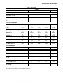
1
Pocket Hardmount Variable-Speed
PS40 Control
Refer to Page 9 for Model Identification
.
Para bajar una copia de estas instrucciones en
español, visite www.comlaundry.com
PHM1397C
PHM1397C
Keep These Instructions for Future Reference.
(If this machine changes ownership, this manual must accompany machine.)
www.comlaundry.com
Part No. F8112101R1
December 2007
Installation
Washer-Extractors
Table of
Contents
Safety Information..............................................................................
Explanation of Safety Messages...........................................................
Important Safety Instructions ...............................................................
Safety Decals ........................................................................................
Operator Safety.....................................................................................
Safe Operating Environment ................................................................
Environmental Conditions ...............................................................
Machine Location ............................................................................
Input and Output Services................................................................
DirectDrive ......................................................................................
Model Identification .............................................................................
3
3
3
5
6
6
6
7
7
8
9
Introduction.........................................................................................
Delivery Inspection...............................................................................
Nameplate Location..............................................................................
Replacement Parts ................................................................................
Customer Service..................................................................................
10
10
10
10
10
Specifications and Dimensions...........................................................
High Speed Models...............................................................................
Medium Speed Models .........................................................................
Machine Dimensions ............................................................................
40 Pound Models ............................................................................
60 Pound Models ............................................................................
80 Pound Models .............................................................................
100 Pound Models ...........................................................................
125 Pound Models ...........................................................................
140 Pound Models ...........................................................................
175 Pound Models ...........................................................................
Front and Rear Features........................................................................
Floor Load Data....................................................................................
Installation Instructions ........................................................................
Surface .............................................................................................
Anchors ............................................................................................
Mounting..........................................................................................
Mounting Bolt Installation Requirements ............................................
Location ...........................................................................................
Clearances ........................................................................................
Installing Anchors ............................................................................
Grouting and Setting Machine .........................................................
Mounting Bolt Hole Locations .............................................................
40 Pound Models ............................................................................
60, 80 and 100 Pound Models..........................................................
125, 140 and 175 Pound Models......................................................
Water Connection .................................................................................
Drain Connection Requirements...........................................................
Electrical Installation Requirements.....................................................
Circuit Breakers ...............................................................................
Grounding ........................................................................................
Wire Size..........................................................................................
11
11
14
16
17
18
19
20
21
22
23
24
26
28
28
28
28
28
28
29
31
31
31
32
34
36
38
39
40
41
41
41
© Copyright 2007, Alliance Laundry Systems LLC
All rights reserved. No part of the contents of this book may be reproduced or transmitted in any form or by any
means without the expressed written consent of the publisher.
F8112101
© Copyright, Alliance Laundry Systems LLC – DO NOT COPY or TRANSMIT
1
Making Connections to Machine .....................................................
Adjusting Control Transformer Taps...............................................
Provisions for 50 Hz Installations....................................................
Steam Requirements (Steam Heat Option Only)..................................
Chemical Injection Supply System.......................................................
Chemical Service Connections ........................................................
Connection of Chemical Supply Hoses ...........................................
Connection of Chemical Pump Signals ...........................................
43
43
43
44
45
45
45
46
First Start-Up ...................................................................................... 47
2
© Copyright, Alliance Laundry Systems LLC – DO NOT COPY or TRANSMIT
F8112101
Safety Information
Explanation of Safety Messages
Precautionary statements (“DANGER,” “WARNING,”
and “CAUTION”), followed by specific instructions,
are found in this manual and on machine decals. These
precautions are intended for the personal safety of the
operator, user, servicer, and those maintaining the
machine.
Important Safety Instructions
WARNING
To reduce the risk of fire, electric shock,
serious injury or death to persons when
using your washer, follow these basic
precautions:
W023
DANGER
1. Read all instructions before using the washer.
DANGER indicates the presence of a
hazard that will cause severe personal
injury, death, or substantial property
damage if the danger is ignored.
WARNING
WARNING indicates the presence of a
hazard that can cause severe personal
injury, death, or substantial property
damage if the warning is ignored.
CAUTION
CAUTION indicates the presence of a
hazard that will or can cause minor
personal injury or property damage if the
caution is ignored.
Additional precautionary statements (“IMPORTANT”
and “NOTE”) are followed by specific instructions.
IMPORTANT: The word “IMPORTANT” is used
to inform the reader of specific procedures where
minor machine damage will occur if the procedure
is not followed.
NOTE: The word “NOTE” is used to communicate
installation, operation, maintenance or servicing
information that is important but not hazard
related.
2. Refer to the GROUNDING INSTRUCTIONS in
the INSTALLATION manual for the proper
grounding of the washer.
3. Do not wash textiles that have been previously
cleaned in, washed in, soaked in, or spotted with
gasoline, kerosene, waxes, cooking oils, drycleaning solvents, or other flammable or
explosive substances as they give off vapors that
could ignite or explode.
4. Do not add gasoline, dry-cleaning solvents, or
other flammable or explosive substances to the
wash water. These substances give off vapors that
could ignite or explode.
5. Under certain conditions, hydrogen gas may be
produced in a hot water system that has not been
used for two weeks or more. HYDROGEN GAS
IS EXPLOSIVE. If the hot water system has not
been used for such a period, before using a
washing machine or combination washer-dryer,
turn on all hot water faucets and let the water
flow from each for several minutes. This will
release any accumulated hydrogen gas. The gas is
flammable, do not smoke or use an open flame
during this time.
6. Do not allow children to play on or in the washer.
Close supervision of children is necessary when
the washer is used near children. This is a safety
rule for all appliances.
7. Before the washer is removed from service or
discarded, remove the door to the washing
compartment.
8. Do not reach into the washer if the wash drum is
moving.
F8112101
© Published by permission of the copyright owner – DO NOT COPY or TRANSMIT
3
Safety Information
9. Do not install or store the washer where it will be
exposed to water and/or weather.
10. Do not tamper with the controls.
11. Do not repair or replace any part of the washer, or
attempt any servicing unless specifically
recommended in the user-maintenance
instructions or in published user-repair
instructions that the user understands and has the
skills to carry out.
12. To reduce the risk of an electric shock or fire, DO
NOT use an extension cord or an adapter to
connect the washer to the electrical power source.
13. Use washer only for its intended purpose,
washing textiles.
14. Never wash machine parts or automotive parts in
the machine. This could result in serious damage
to the basket.
15. ALWAYS disconnect the washer from electrical
supply before attempting any service. Disconnect
the power cord by grasping the plug, not the cord.
16. Install the washer according to the
INSTALLATION INSTRUCTIONS. All
connections for water, drain, electrical power and
grounding must comply with local codes and be
made by licensed personnel when required.
17. To reduce the risk of fire, textiles which have
traces of any flammable substances such as
vegetable oil, cooking oil, machine oil,
flammable chemicals, thinner, etc., or anything
containing wax or chemicals such as in mops and
cleaning cloths, must not be put into the washer.
These flammable substances may cause the
fabric to catch on fire by itself.
18. Do not use fabric softeners or products to
eliminate static unless recommended by the
manufacturer of the fabric softener or product.
20. Be sure water connections have a shut-off valve
and that fill hose connections are tight. CLOSE
the shut-off valves at the end of each wash day.
21. Loading door MUST BE CLOSED any time the
washer is to fill, tumble or spin. DO NOT bypass
the loading door switch by permitting the washer
to operate with the loading door open.
22. Always read and follow manufacturer’s
instructions on packages of laundry and cleaning
aids. Heed all warnings or precautions. To reduce
the risk of poisoning or chemical burns, keep
them out of the reach of children at all times
(preferably in a locked cabinet).
23. Always follow the fabric care instructions
supplied by the textile manufacturer.
24. Never operate the washer with any guards and/or
panels removed.
25. DO NOT operate the washer with missing or
broken parts.
26. DO NOT bypass any safety devices.
27. Failure to install, maintain, and/or operate this
washer according to the manufacturer’s
instructions may result in conditions which can
produce bodily injury and/or property damage.
NOTE: The WARNINGS and IMPORTANT
SAFETY INSTRUCTIONS appearing in this
manual are not meant to cover all possible
conditions and situations that may occur. Common
sense, caution and care must be exercised when
installing, maintaining, or operating the washer.
Any problems or conditions not understood should be
reported to the dealer, distributor, service agent or the
manufacturer.
19. Keep washer in good condition. Bumping or
dropping the washer can damage safety features.
If this occurs, have washer checked by a qualified
service person.
4
© Published by permission of the copyright owner – DO NOT COPY or TRANSMIT
F8112101
Safety Information
WARNING
CAUTION
This machine must be installed, adjusted,
and serviced by qualified electrical
maintenance personnel familiar with the
construction and operation of this type of
machinery. They must also be familiar
with the potential hazards involved.
Failure to observe this warning may result
in personal injury and/or equipment
damage, and may void the warranty.
SW004
IMPORTANT: Ensure that the recommended
clearances for inspection and maintenance are
provided. Never allow the inspection and
maintenance space to be blocked.
Be careful around the open door,
particularly when loading from a level
below the door. Impact with door edges
can cause personal injury.
SW025
WARNING
Never touch internal or external steam
pipes, connections, or components.
These surfaces can be extremely hot and
will cause severe burns. The steam must
be turned off and the pipe, connections,
and components allowed to cool before
the pipe can be touched.
CAUTION
SW014
Install the machine on a level floor of
sufficient strength. Failure to do so may
result in conditions which can produce
serious injury, death and/or property
damage.
W703
Safety Decals
Safety decals appear at crucial locations on the
machine. Failure to maintain legible safety decals
could result in injury to the operator or service
technician.
To provide personal safety and keep the machine in
proper working order, follow all maintenance and
safety procedures presented in this manual. If
questions regarding safety arise, contact the
manufacturer immediately.
Use manufacturer-authorized spare parts to avoid
safety hazards.
F8112101
© Published by permission of the copyright owner – DO NOT COPY or TRANSMIT
5
Safety Information
Operator Safety
Safe Operating Environment
WARNING
NEVER insert hands or objects into
basket until it has completely stopped.
Doing so could result in serious injury.
SW012
To ensure the safety of machine operators, the
following maintenance checks must be performed
daily:
Safe operation requires an appropriate operating
environment for both the operator and the machine. If
questions regarding safety arise, contact the
manufacturer immediately.
Environmental Conditions
●
Ambient Temperature. Water in machine will
freeze at temperatures of 32°F (0°C) or below.
●
Temperatures above 120°F (50°C) will result in
more frequent motor overheating and, in some
cases, malfunction or premature damage to solid
state devices that are used in some models.
Special cooling devices may be necessary.
●
Water pressure switches are affected by increases
and decreases in temperature. Every 25°F (10°C)
change in temperature will have a 1% effect on
the water level.
●
Humidity. Relative humidity above 90% may
cause machine’s electronics or motors to
malfunction or may trip ground fault interrupter.
Corrosion problems may occur on some metal
components in machine.
●
If relative humidity is below 30%, belts and
rubber hoses may eventually develop dry rot.
This condition can result in hose leaks, which
may cause safety hazards external to machine in
conjunction with adjacent electrical equipment.
●
Ventilation. The need for make-up air openings
for such laundry room accessories as dryers,
ironers, water heaters, etc., must be evaluated
periodically. Louvers, screens or other separating
devices may reduce available air opening
significantly.
●
Radio Frequency Emissions. A filter is available
for machines in installations where floor space is
shared with equipment sensitive to radio
frequency emissions.
●
Elevation. If machine is to be operated at
elevations of over 3280 feet (1000 m) above sea
level, pay special attention to water levels and
electronic settings (particularly temperature) or
desired results may not be achieved.
●
Chemicals. Keep stainless steel surfaces free of
chemical residues.
1. Prior to operating machine, verify that all
warning signs are present and legible. Missing or
illegible signs must be replaced immediately.
Make certain that spares are available.
2. Check door interlock before starting operation of
machine:
a. Attempt to start machine with door open.
Machine should not start with door open.
b. Close door without locking it and attempt to
start machine. Machine should not start with
door unlocked.
c. Close and lock door and start a cycle. Attempt
to open door while cycle is in progress. Door
should not open.
If door lock and interlock are not functioning
properly, call a service technician.
3. Do not attempt to operate machine if any of the
following conditions are present:
a. Door does not remain securely locked during
entire cycle.
b. Excessively high water level is evident.
c. Machine is not connected to a properly
grounded circuit.
Do not bypass any safety devices in machine.
WARNING
Never operate the machine with a
bypassed or disconnected balance
system. Operating the machine with
severe out-of-balance loads could result
in personal injury and serious equipment
damage.
SW039
6
© Published by permission of the copyright owner – DO NOT COPY or TRANSMIT
F8112101
Safety Information
Input and Output Services
DANGER
Do not place volatile or flammable fluids
in any machine. Do not clean the machine
with volatile or flammable fluids such as
acetone, lacquer thinners, enamel
reducers, carbon tetrachloride, gasoline,
benzene, naptha, etc. Doing so could
result in serious personal injury and/or
damage to the machine.
SW002
●
●
Water Pressure. Best performance will be
realized if water is provided at a pressure of 30 –
85 psi (2 – 5.7 bar). Although machine will
function properly at lower pressure, increased fill
times will occur. Water pressure higher than 100
psi (6.7 bar) may result in damage to machine
plumbing. Component failure(s) and personal
injury could result.
●
Steam Heat (Optional) Pressure. Best
performance will be realized if steam is provided
at a pressure of 30 – 80 psi (2 – 5.4 bar). Steam
pressure higher than 125 psi (8.5 bar) may result
in damage to steam components and may cause
personal injury.
●
For machines equipped with optional steam heat,
install piping in accordance with approved
commercial steam practices. Failure to install
supplied steam filter may void warranty.
●
Drainage System. Provide drain lines or troughs
large enough to accommodate total number of
gallons that could be released if all machines on
site drained at same time from highest attainable
level. If troughs are used, they should be covered
to support light foot traffic.
●
Power. For personal safety and for proper
operation, machine must be grounded in
accordance with state and local codes. Ground
connection must be to a proven earth ground, not
to conduit or water pipes. Do not use fuses in
place of circuit breaker. An easy-access cutoff
switch should also be provided.
Water Damage. Do not spray machine with
water. Short circuiting and serious damage may
result. Repair immediately all seepage due to
worn or damaged gaskets, etc.
Machine Location
●
●
Foundation. The concrete floor must be of
sufficient strength and thickness to handle floor
loads generated by high extract speeds of
machine.
Service/Maintenance Space. Provide sufficient
space to allow comfortable performance of
service procedures and routine preventive
maintenance.
Consult installation instructions for specific details.
CAUTION
Replace all panels that are removed to
perform service and maintenance
procedures. Do not operate the machine
with missing guards or with broken or
missing parts. Do not bypass any safety
devices.
SW019
WARNING
Ensure that a ground wire from a proven
earth ground is connected to the ground
lug near the input power block on this
machine. Without proper grounding,
personal injury from electric shock could
occur and machine malfunctions may be
evident.
SW008
Always disconnect power and water supplies before a
service technician performs any service procedure.
Where applicable, steam and/or compressed air
supplies should also be disconnected before service is
performed.
F8112101
© Published by permission of the copyright owner – DO NOT COPY or TRANSMIT
7
Safety Information
DirectDrive
●
Machines equipped with DirectDrive require special
attention with regard to operating environment.
●
●
8
An especially dusty or linty environment will
require more frequent cleaning of AC inverter
drive cooling fan filter and of AC inverter drive
itself.
Power line fluctuations from sources such as
uninterruptible power supplies (UPS) can
adversely affect machines equipped with AC
inverter drive. Proper suppression devices should
be utilized on incoming power to machine to
avoid problems.
A clean power supply free from voltage spikes
and surges is absolutely essential for machines
equipped with AC inverter drive. Inconsistencies
(peaks and valleys) in power supply can cause
AC inverter drive to generate nuisance errors.
If voltage is above 230 Volt for 200 Volt
installation or 460 Volt for 400 Volt installation,
ask power company to correct. As an alternative,
a step-down transformer kit is available from
distributor. If voltage is above 240 Volt for 200
Volt installation or 480 Volt for 400 Volt
installations, a buckboost transformer is required.
●
Sufficient space to perform service procedures
and routine preventive maintenance is especially
important for machines equipped with AC
inverter drive.
© Published by permission of the copyright owner – DO NOT COPY or TRANSMIT
F8112101
Safety Information
Model Identification
Information in this manual is applicable to these
models:
Medium Speed
High Speed
40
Pound
CP040PMN1
CP040PMQ1
CP040PMX1
CPC40M
IP040PMN1
IP040PMQ1
IP040PMX1
IPH40M
IPH180
CP040PHN1
CP040PHQ1
CP040PHX1
CPC40H
IP040PHN1
IP040PHQ1
IP040PHX1
IPH40H
JP040PHN1
JP040PHQ1
60
Pound
CP060PMN1
CP060PMQ1
CP060PMX1
CPC60M
IP060PMN1
IP060PMQ1
IP060PMX1
IPH60M
IPH270
JP060PMQ1
CP060PHN1
CP060PHQ1
CP060PHX1
CPC60H
IP060PHN1
IP060PHQ1
IP060PHX1
IPH60H
JP060PHN1
JP060PHQ1
80
Pound
CP080PMN1
CP080PMQ1
CPC80M
IP080PMN1
IP080PMQ1
IPH80M
IPH370
CP080PHN1
CP080PHQ1
CPC80H
IP080PHN1
IP080PHQ1
IPH80H
JP080PHN1
JP080PHQ1
100
Pound
CP100PMN1
CP100PMQ1
CPC100M
IP100PMN1
IP100PMQ1
IPH100M
IPH460
JP100PMQ1
CP100PHN1
CP100PHQ1
CPC100H
IP100PHN1
IP100PHQ1
IPH100H
JP100PHN1
JP100PHQ1
CP125PHN1
CP125PHQ1
CPC125H
IP125PHN1
IP125PHQ1
IPH125H
IPH570
JP125PHN1
CP140PHN1
CP140PHQ1
CPC140H
IP140PHN1
IP140PHQ1
IPH140H
JP140PHN1
JP140PHQ1
CP175PHN1
CPC175H
IP175PHN1
IPH175H
IPH790
125
Pound
140
Pound
Not Applicable
IP140PMQ1
IPH140M
IPH640
JP140PMQ1
CP140PMN1
CP140PMQ1
CPC140M
IP140PMN1
175
Pound
Not Applicable
Model Number Familiarization Guide
Sample Model Number: IP060PMQ1
I
Model Number Prefix Brand
P
Product Family; P=IPH
060
Washer-Extractor Capacity
(pounds dry weight of laundry)
P
Type of Control; P=PS40
M
Spin Speed; M=Medium
Q
Electrical Voltage; Q=200-208/220-240 Volt/50 or 60 Hertz/3 Phase
F8112101
© Published by permission of the copyright owner – DO NOT COPY or TRANSMIT
9
Introduction
This manual is designed as a guide for the installation
of a washer-extractor equipped with DirectDrive.
NOTE: All information, illustrations and
specifications contained in this manual are based
on the latest product information available at the
time of printing. We reserve the right to make
changes at any time without notice.
Delivery Inspection
Upon delivery, visually inspect crate, protective cover
and unit for any visible shipping damage. If the crate,
protective cover or unit is damaged or signs of possible
damage are evident, have the carrier note the condition
on the shipping papers before the shipping receipt is
signed or advise the carrier of the condition as soon as
it is discovered.
Remove the crate and protective cover as soon after
delivery as possible. If any damage is discovered upon
removal of the crate and/or protective cover, advise the
carrier and file a written claim immediately.
Replacement Parts
If literature or replacement parts are required, contact
the source from which the washer-extractor was
purchased or contact Alliance Laundry Systems LLC
at (920) 748-3950 for the name of the nearest
authorized parts distributor. A parts manual may be
ordered by returning the reply card provided with each
washer-extractor.
Customer Service
For technical assistance, contact your local distributor
or call:
(920) 748-3121
Ripon, Wisconsin
A record of each washer-extractor is on file with the
manufacturer. Always provide the machine’s serial
number and model number when ordering parts or
when seeking technical assistance. Refer to Figure 1.
Nameplate Location
The nameplate is located inside the door and on the
upper rear panel. Always provide the machine’s serial
number and model number when ordering parts or
when seeking technical assistance. Refer to Figure 1.
2
1
PHM1397C
PHM1397N
1
2
Inside the Door
On Upper Rear Panel
Figure 1
10
© Published by permission of the copyright owner – DO NOT COPY or TRANSMIT
F8112101
Specifications and Dimensions
High Speed Models
.
Models
Specifications
40H
60H
80H
100H
125H
140H
175H
Overall Width, in. (mm)
32
(813)
34.5
(876)
42.5
(1080)
42.5
(1080)
56.3
(1430)
56.3
(1276)
56.3
(1276)
Overall Height, in. (mm)
57
(1448)
62.6
(1590)
70
(1778)
70
(1778)
77.1
(1958)
77.1
(1958)
77.1
(1958)
Overall Depth, in. (mm)
45.6
(1158)
47.8
(1213)
51.4
(1306)
56.4
(1433)
56.1
(1425)
59.1
(1502)
64
(1626)
Overall Dimensions
Weight and Shipping Information
Net Weight, lbs. (kg)
1690
(768.2)
1795
(815.9)
1926
(875.5)
2167
(985)
2749
(1247)
3027
(1375.9)
3277
(1489.5)
Domestic Shipping
Weight, lbs. (kg)
1770
(804.5)
1895
(861.3)
2026
(920.9)
2267
(1030.5)
2849
(1292)
3127
(1421.3)
3377
(1535)
Domestic Shipping
Volume, ft.3 (m3)
63
(1.78)
76.9
(2.18)
110
(3.11)
122
(3.45)
160
(4.53)
167
(4.73)
179
(5.16)
Wash Cylinder Information
Cylinder Diameter,
in. (mm)
27
(686)
31
(787)
37
(940)
37
(940)
43
(1092)
43
(1092)
43
(1092)
Cylinder Depth,
in. (mm)
19
(483)
22
(559)
21
(533)
26
(660)
24
(610)
27
(686)
32
(813)
Cylinder Volume,
ft.3 (l)
6.3
(178.3)
9.6
(271.7)
13.1
(370.7)
16.2
(458.5)
20.1
(569.2)
22.7
(642.4)
26.8
(759.9)
Perforation Size,
in. (mm)
0.19
(4.83)
0.19
(4.83)
0.19
(4.83)
0.19
(4.83)
0.19
(4.83)
0.19
(4.83)
0.19
(4.83)
Cylinder Capacity 1:10
Fill Ratio, lbs. (kg)
39.3
(17.8)
60
(27.2)
81.6
(37)
101
(45.9)
125
(57)
141.7
(64.3)
175
(79.5)
Door Opening Information
Door Opening Size,
in. (mm)
15
(381)
17
(432)
20
(508)
20
(508)
24.5
(622)
24.5
(622)
24.5
(622)
Height of Door Bottom
Above Floor, in. (mm)
25.5
(648)
28.8
(730)
29.6
(752)
30.1
(765)
34
(837)
34.3
(871)
34.8
(884)
Overflow Size,
in. (mm)
1.5
(38.1)
1.5
(38.1)
1.5
(38.1)
1.5
(38.1)
3
(76.2)
3
(76.2)
3
(76.2)
Drain Outlet Size,
in. (mm)
3
(76.2)
3
(76.2)
3
(76.2)
3
(76.2)
3
(76.2)
3
(76.2)
3
(76.2)
Number of Drain
Outlets, (std/opt)
1/2
1/2
1/2
1/2
1/2
1/2
1/2
Drain System
Table 1 (continued)
All specifications are subject to change without notification.
F8112101
© Published by permission of the copyright owner – DO NOT COPY or TRANSMIT
11
Specifications and Dimensions
Table 1 (continued)
Models
Specifications
40H
60H
80H
100H
125H
140H
175H
3/4 NPT
3/4 NPT
3/4 NPT
3/4 NPT
3/4 NPT
1-1/4 NPT
1-1/4 NPT
2/3
2/3
2/3
2/3
2/3
2/3
2/3
Number of Dry
Chemical
Compartments,
(std/opt)
1/5
1/5
1/5
1/5
1/5
1/5
1/5
Number of Liquid
Supply Connections,
(std/opt)
6/12
6/12
6/12
6/12
6/12
6/12
6/12
Water Inlet
Connection Size
Number of Inlets,
(std/opt)
Chemical Supply System
Cylinder Speeds/Centrifugal Force Data
6
(0.014)
6
(0.016)
6
(0.019)
6
(0.019)
6
(0.022)
6
(0.022)
6
(0.022)
Wash Speed,
RPM (G-Force)
46
(0.8)
43
(0.8)
39
(0.8)
39
(0.8)
36
(0.8)
36
(0.8)
36
(0.8)
Balance Speed,
RPM (G-Force)
72
(2)
67
(2)
62
(2)
62
(2)
57
(2)
57
(2)
57
(2)
Low Extract Speed,
RPM (G-Force)
511
(100)
477
(100)
437
(100)
437
(100)
405
(100)
405
(100)
405
(100)
Medium Extract Speed,
RPM (G-Force)
605
(140)
564
(140)
516
(140)
516
(140)
479
(140)
479
(140)
479
(140)
High Extract Speed,
RPM (G-Force)
775
(230)
723
(230)
662
(230)
662
(230)
573
(200)
573
(200)
573
(200)
Maximum SmartSpin
Speed, RPM (G-Force)
885
(300)
826
(300)
756
(300)
756
(300)
701
(300)
640
(250)
640
(250)
1
1
1
1
1
1
1
3
(2.3)
5
(3.7)
7.5
(5.6)
7.5
(5.6)
10
(7.5)
7.5
(5.6)
15
(11.2)
STD
STD
STD
STD
STD
STD
STD
Not
Applicable
Not
Applicable
Not
Applicable
Low Wash Speed,
RPM (G-Force)
Drive Train Information
Number of Motors In
Drive Train
Drive Motor Power,
hp (kW)
Balance Detection
Vibration Switch
Installed
Electrical Heating (Optional)
Total Electrical Heating
Capacity, kW
Number of Electrical
Heating Elements
Electrical Heating
Element Size, kW
21.5@240V 32.2@240V 32.2@240V 32.2@240V
21.5@480V 21.5@480V 21.5@480V 21.5@480V
6 – 240V
6 – 480V
9 – 240V
6 – 480V
9 – 240V
6 – 480V
9 – 240V
6 – 480V
Not
Applicable
Not
Applicable
Not
Applicable
3
3
3
3
Not
Applicable
Not
Applicable
Not
Applicable
Table 1 (continued)
All specifications are subject to change without notification.
12
© Published by permission of the copyright owner – DO NOT COPY or TRANSMIT
F8112101
Specifications and Dimensions
Table 1 (continued)
Models
Specifications
40H
60H
80H
100H
125H
140H
175H
Electrical Connections (Non-electric Heated Models)
Max. Circuit Breaker
Size (200-240V, 3P)
15
15
20
20
30
30
Not
Applicable
Max. Circuit Breaker
Size (380-480V, 3P)
15
15
15
15
15
15
20
Table 1
All specifications are subject to change without notification.
F8112101
© Published by permission of the copyright owner – DO NOT COPY or TRANSMIT
13
Specifications and Dimensions
Medium Speed Models
.
Models
Specifications
40M
60M
80M
100M
140M
Overall Width, in. (mm)
32
(813)
34.5
(876)
42
(1080)
42.5
(1080)
50.3
(1276)
Overall Height, in. (mm)
57
(1448)
62.6
(1590)
70
(1778)
70
(1778)
77.1
(1958)
Overall Depth, in. (mm)
45.6
(1158)
47.8
(1213)
51.4
(1306)
56.4
(1433)
59.1
(1502)
Overall Dimensions
Weight and Shipping Information
Net Weight, lbs. (kg)
110
(499)
1175
(533)
1630
(740)
1770
(804)
2300
(1044)
Domestic Shipping Weight,
lbs. (kg)
1180
(536)
1250
(567)
1730
(785)
1870
(849)
2450
(1112)
Domestic Shipping Volume,
ft.3 (m3)
63
(1.78)
76.9
(2.18)
110
(3.11)
122
(3.45)
167
(4.73)
Cylinder Diameter,
in. (mm)
27
(686)
31
(787)
37
(940)
37
(940)
43
(1092)
Cylinder Depth, in. (mm)
19
(483)
22
(559)
21
(533)
26
(660)
27
(686)
Cylinder Volume, ft.3 (l)
6.3
(178.3)
9.6
(271.7)
13.1
(370.7)
16.2
(458.5)
22.7
(642.4)
Perforation Size, in. (mm)
0.19
(4.83)
0.19
(4.83)
0.19
(4.83)
0.19
(4.83)
0.19
(4.83)
Cylinder Capacity 1:10 Fill
Ratio, lbs. (kg)
39.3
(17.8)
60
(27.2)
81.6
(37)
101
(45.9)
141.7
(64.3)
Door Opening Size,
in. (mm)
15
(381)
17
(432)
20
(508)
20
(508)
24.5
(622)
Height of Door Bottom
Above Floor, in. (mm)
25.5
(648)
28.8
(730.3)
29.6
(751.8)
30.1
(765)
34.3
(871.2)
Overflow Size, in. (mm)
1.5
(38.1)
1.5
(38.1)
1.5
(38.1)
1.5
(38.1)
3
(76.2)
Drain Outlet Size, in. (mm)
3
(76.2)
3
(76.2)
3
(76.2)
3
(76.2)
3
(76.2)
1/2
1/2
1/2
1/2
1/2
3/4 NPT
3/4 NPT
3/4 NPT
3/4 NPT
1-1/4 NPT
2/3
2/3
2/3
2/3
2/3
Wash Cylinder Information
Door Opening Information
Drain System
Number of Drain Outlets,
(std/opt)
Water Inlet
Connection Size
Number of Inlets, (std/opt)
Table 2 (continued)
All specifications are subject to change without notification.
14
© Published by permission of the copyright owner – DO NOT COPY or TRANSMIT
F8112101
Specifications and Dimensions
Table 2 (continued)
Models
Specifications
40M
60M
80M
100M
140M
Number of Dry Chemical
compartments, (std/opt)
1/5
1/5
1/5
1/5
1/5
Number of Liquid Supply
Connections, (std/opt)
6/12
6/12
6/12
6/12
6/12
Liquid Supply Connection
Size
1/2 NPT
1/2 NPT
1/2 NPT
1/2 NPT
1/2 NPT
1
1
1
1
1
3
(2.3)
3
(2.3)
5
(3.7)
5
(3.7)
7.5
(5.6)
6
(0.014)
6
(0.016)
6
(0.019)
6
(0.019)
6
(0.022)
Wash Speed,
RPM (G-Force)
46
(0.8)
43
(0.8)
39
(0.8)
39
(0.8)
36
(0.8)
Balance Speed,
RPM (G-Force)
72
(2)
67
(2)
62
(2)
62
(2)
57
(2)
Extract Speed,
RPM (G-Force)
511
(100)
477
(100)
437
(100)
437
(100)
405
(100)
Maximum SmartSpin
Speed, RPM (G-Force)
625
(150)
585
(150)
535
(150)
535
(150)
500
(152)
STD
STD
STD
STD
STD
21.5@240V
21.5@480V
32.2@240V
21.5@480V
32.2@240V
21.5@480V
32.2@240V
21.5@480V
Not Applicable
6 – 240V
6 – 480V
9 – 240V
6 – 480V
9 – 240V
6 – 480V
9 – 240V
6 – 480V
Not Applicable
3
3
3
3
Not Applicable
Chemical Supply System
Drive Train Information
Number of Motors In Drive
Train
Drive Motor Power,
hp (kW)
Cylinder Speeds/Centrifugal Force Data
Low Wash Speed,
RPM (G-Force)
Balance Detection
Vibration Switch Installed
Electrical Heating (Optional)
Total Electrical Heating
Capacity, kW
Number of Electrical
Heating Elements
Electrical Heating Element
Size, kW
Electrical Connections (Non-electric Heated Models)
Max. Circuit Breaker Size
(200-240V, 3P)
15
15
15
15
20
Max. Circuit Breaker Size
(380-480V, 3P)
15
15
15
15
15
Table 2
All specifications are subject to change without notification.
F8112101
© Published by permission of the copyright owner – DO NOT COPY or TRANSMIT
15
Specifications and Dimensions
Machine Dimensions
Dimensional Clearances
Allow a minimum of 24 inches (600 mm) at the rear
and 18 inches (450 mm) at the sides for maintenance,
inspection and adjustment. Allow at least 18 inches
(450 mm) between machines in multiple installations.
Machine dimensions are indicated in Figure 2 through
Figure 8. For minimum clearances, refer to Figure 10.
16
NOTE: The dimensions shown here are for
planning purposes only. They are approximate and
subject to normal manufacturing tolerances. If
exact dimensions are required for construction
purposes, contact the distributor or the
manufacturer. We reserve the right to make
changes at any time without notice.
© Published by permission of the copyright owner – DO NOT COPY or TRANSMIT
F8112101
Specifications and Dimensions
40 Pound Models
L
4
K
3
1
5
J
2
6
7
A
E
F
C
O
G
N
H
M
D
I
B
P
10
8
9
REAR
FRONT
TOP
PHM727N
PHM727N
1
2
3
4
5
External Supply Connection
Auxiliary
Hot Water
Cold Water
Greasing Points
6
7
8
9
10
External Supply Wiring Connection
Power Inlet
Steam Inlet
Auxiliary Drain
Drain
Figure 2
A
45.6 in. (1158 mm)
I
11.7 in. (297 mm)
B
32 in. (813 mm)
J
10.25 in. (260 mm)
C
25.5 in. (648 mm)
K
19.35 in. (491 mm)
D
22.5 in. (572 mm)
L
27.93 in. (709 mm)
E
57 in. (1448 mm)
M
21.8 in. (554 mm)
F
52 in. (1321 mm)
N
43 in. (1092 mm)
G
48 in. (1219 mm)
O
51.4 in. (1306 mm)
H
44 in. (1118 mm)
P
8.88 in. (226 mm)
Table 3
F8112101
© Published by permission of the copyright owner – DO NOT COPY or TRANSMIT
17
Specifications and Dimensions
60 Pound Models
M
4
L
3
1
5
K
2
6
7
10
A
E
C
F
G
H
N
O
I
D
J
B
P
9
8
TOP
PHM728N
REAR
FRONT
PHM728N
1
2
3
4
5
External Supply Connection
Auxiliary
Hot Water
Cold Water
Greasing Points
6
7
8
9
10
External Supply Wiring Connection
Power Inlet
Auxiliary Drain
Drain
Steam Inlet
Figure 3
A
47.8 in. (1213 mm)
I
38.5 in. (978 mm)
B
34.5 in. (876 mm)
J
11.7 in. (297 mm)
C
28.8 in. (732 mm)
K
11.5 in. (292 mm)
D
25.8 in. (656 mm)
L
21.1 in. (536 mm)
E
62.6 in. (1590 mm)
M
29.69 in. (754 mm)
F
57.62 in. (1464 mm)
N
48.6 in. (1234 mm)
G
53.62 in. (1362 mm)
O
57.1 in. (1450 mm)
H
49.62 in. (1260 mm)
P
9.63 in. (245 mm)
Table 4
18
© Published by permission of the copyright owner – DO NOT COPY or TRANSMIT
F8112101
Specifications and Dimensions
80 Pound Models
O
1
4
3
2
N
5
M
6
7
10
A
G
F
E
C
H
I
P
J
Q
K
D
L
B
R
S
9
8
TOP
PHM729N
REAR
FRONT
PHM729N
1
2
3
4
5
External Supply Connection
Auxiliary
Hot Water
Cold Water
Greasing Points
6
7
8
9
10
External Supply Wiring Connection
Power Inlet
Auxiliary Drain
3 in. (76.2 mm) Drain
Steam Inlet
Figure 4
A
51.4 in. (1306 mm)
K
38.4 in. (975 mm)
B
42.5 in. (1080 mm)
L
11.7 in. (297 mm)
C
29.6 in. (752 mm)
M
12.25 in. (311 mm)
D
26.6 in. (676 mm)
N
29 in. (737 mm)
E
52 in. (1321 mm)
O
37.7 in. (958 mm)
F
61.05 in. (1562 mm)
P
56 in. (1422 mm)
G
70 in. (1778 mm)
Q
64.4 in. (1636 mm)
H
66 in. (1678 mm)
R
12 in. (305 mm)
I
62 in. (1575 mm)
S
6 in. (152 mm)
J
58 in. (1473 mm)
Table 5
F8112101
© Published by permission of the copyright owner – DO NOT COPY or TRANSMIT
19
Specifications and Dimensions
100 Pound Models
O
1
4
3
2
N
5
M
6
7
10
A
F
G H
E
I
Q
P
J
I
K
C
D
L
B
9
S
R
8
TOP
REAR
FRONT
PHM730N
PHM730N
1
2
3
4
5
External Supply Connection
Auxiliary
Hot Water
Cold Water
Greasing Points
6
7
8
9
10
External Supply Wiring Connection
Power Inlet
Auxiliary Drain
3 in. (76.2 mm) Drain
Steam Inlet
Figure 5
A
56.4 in. (1433 mm)
K
38.4 in. (975 mm)
B
42.5 in. (1080 mm)
L
11.7 in. (297 mm)
C
30.12 in. (765 mm)
N
29 in. (737 mm)
D
27.13 in. (689 mm)
O
37.7 in. (958 mm)
E
52 in. (1321 mm)
M
12.25 in. (311 mm)
F
61.05 in. (1562 mm)
P
56 in. (1422 mm)
G
70 in. (1778 mm)
Q
64.4 in. (1636 mm)
H
66 in. (1676 mm)
R
12 in. (305 mm)
I
62 in. (1575 mm)
S
6 in. (152 mm)
J
58 in. (1473 mm)
Table 6
20
© Published by permission of the copyright owner – DO NOT COPY or TRANSMIT
F8112101
Specifications and Dimensions
125 Pound Models
Q
O
3
P
N
4
5
2
6
1
9
G
A
H
F
E
C
J
R
K
S
L
D
M
B
T
U
TOP
I
REAR
FRONT
8
7
PHM731N
1
2
3
4
5
External Supply Connection
Hot Water
Cold Water
Auxiliary
External Supply Wiring Connection
6
7
8
9
Power Inlet
3 in. (76.2 mm) Drain
Auxiliary Drain
Steam Inlet
Figure 6
A
56.1 in. (1425 mm)
L
45.3 in. (1149 mm)
B
50.3 in. (1278 mm)
M
11.6 in. (294 mm)
C
34.3 in. (871 mm)
N
6.7 in. (171 mm)
D
31.3 in. (795 mm)
O
18.1 in. (460 mm)
E
58 in. (1473 mm)
P
28.8 in. (732 mm)
F
67.6 in. (1717 mm)
Q
31.1 in. (789 mm)
G
77.1 in. (1958 mm)
R
63.8 in. (1621 mm)
H
71.7 in. (1821 mm)
S
70.2 in. (1784 mm)
I
67.7 in. (1719 mm)
T
19.4 in. (492 mm)
J
64.5 in. (1638 mm)
U
6 in. (152 mm)
K
63.7 in. (1618 mm)
Table 7
F8112101
© Published by permission of the copyright owner – DO NOT COPY or TRANSMIT
21
Specifications and Dimensions
140 Pound Models
P
O
N
3
2
M
L
4
5
1
G
A
F
E
6
R
H
10
Q
I
C D
7
J
K
B
S
T
TOP
9
FRONT
8
REAR
PHM732N
PHM732N
1
2
3
4
5
External Supply Connection
Cold Water
Hot Water
Auxiliary
External Supply Wiring Connection
6
7
8
9
10
Power Inlet
Greasing Points
Auxiliary Drain
3 in. (76.2 mm) Drain
Steam Inlet
Figure 7
A
59.1 in. (1502 mm)
K
11.7 in. (297 mm)
B
50.3 in. (1276 mm)
L
12 in. (305 mm)
C
34.3 in. (871 mm)
M
15.18 in. (386 mm)
D
31.3 in. (795 mm)
N
17 in. (432 mm)
E
58 in. (1473 mm)
O
36.7 in. (932 mm)
F
67.6 in. (1717 mm)
P
45.26 in. (1150 mm)
G
82 in. (2083 mm)
Q
56 in. (1422 mm)
H
70.8 in. (1798 mm)
R
64.4 in. (1636 mm)
I
65.7 in. (1502 mm)
S
19.3 in. (490 mm)
J
45.6 in. (1158 mm)
T
6 in. (152 mm)
Table 8
22
© Published by permission of the copyright owner – DO NOT COPY or TRANSMIT
F8112101
Specifications and Dimensions
175 Pound Models
P
O
N
3
2
M
L
4
5
1
G
A
F
C
R
10
H
Q
I
E
6
7
J
D
K
B
S
T
TOP
9
FRONT
8
REAR
PHM733N
1
2
3
4
5
External Supply Connection
Cold Water
Hot Water
Auxiliary
External Supply Wiring Connection
6
7
8
9
10
Power Inlet
Greasing Points
Auxiliary Drain
3 in. (76.2 mm) Drain
Steam Inlet
Figure 8
A
64.1 in. (1628 mm)
K
11.7 in. (297 mm)
B
50.3 in. (1276 mm)
L
12 in. (305 mm)
C
34.3 in. (871 mm)
M
15.18 in. (386 mm)
D
31.3 in. (795 mm)
N
17 in. (432 mm)
E
58 in. (1473 mm)
O
36.7 in. (932 mm)
F
67.6 in. (1717 mm)
P
45.26 in. (1150 mm)
G
77.1 in. (1958 mm)
Q
56 in. (1422 mm)
H
70.8 in. (1798 mm)
R
64.4 in. (1636 mm)
I
65.3 in. (1658 mm)
S
19.3 in. (490 mm)
J
45.5 in. (1155 mm)
T
6 in. (152 mm)
Table 9
F8112101
© Published by permission of the copyright owner – DO NOT COPY or TRANSMIT
23
Specifications and Dimensions
Front and Rear Features
5
11
6
12
10
13
14
4
3
2
9
15
8
7
1
16
FRONT
PHM687N
REAR
PHM687N
1
2
3
4
5
6
7
8
Front Service Panel
Door Release Panel
Door Handle
Loading Door
Control Panel
Supply Dispenser
Rear Service Panel
Steam Service Connection
9
10
11
12
13
14
15
16
Chemical Service Connection
Water Service Connections
Lubrication Points for Bearings
Top Service Panel
Chemical Signal Control Connection
Power Service Connection
Cooling Fan and Filter
Drain Service Connections
Figure 9
24
© Published by permission of the copyright owner – DO NOT COPY or TRANSMIT
F8112101
Specifications and Dimensions
See next two pages for Floor Load Data
F8112101
© Published by permission of the copyright owner – DO NOT COPY or TRANSMIT
25
Height
of
Basket
Center
(in.)
Max
RPM
G
Calculated
Static
Load
(lbs.)
Static
Floor
Pressure
(lbs./ft.2)
Dynamic
Load
(lbs.)
Max
Vertical
Load
(lbs.)
Max
Dynamic
Floor
Pressure
(lbs./ft.2)
Base
Moment
(lbs./ft.)
Load
Freq
(Hz)
© Copyright, Alliance Laundry Systems LLC – DO NOT COPY or TRANSMIT
Machine
Size
Basket
Diameter
Net Wt.
of
Machine
(lbs.)
40M 100G
27
1583
33.35
511
100
1701
179
786
2440
256.8
2185
8.52
40M 150G
27
1583
33.35
625
149.6
1701
179
706
2359
248.3
1961
10.42
40H 230G
27
1690
33.35
775
230
1808
190.3
1808
3569
375.7
5025
12.92
40H 300G
27
1690
33.35
885
300
1808
190.3
1415
3175
334.2
3931
14.75
60M 100G
31
1627
37.2
477
100
1807
170.9
1201
2936
277.7
3722
7.95
60M 150G
31
1627
37.2
585
150.5
1807
170.9
1083
2818
266.6
3359
9.75
60H 230G
31
1795
37.2
723
229.9
1975
186.8
2758
4661
440.9
8551
125
60H 300G
31
1795
37.2
826
300
1975
186.8
2160
4063
384.3
6696
13.77
80M 100G
37
1766
40
437
100.2
2011
139.2
1636
3549
245.7
5452
7.28
80M 150G
37
1766
40
535
150.2
2011
139.2
1471
3384
234.3
4903
8.92
80H 230G
37
1926
40
662
230
2171
150.3
3754
5826
403.5
12512
11.03
80H 300G
37
1926
40
756
300
2171
150.3
2937
5010
346.9
9791
12.6
100M 100G
37
2007
40.3
437
100.2
2310
145.1
2025
4213
264.7
6799
7.28
100M 150G
37
2007
40.3
535
150.2
2310
145.1
1821
4009
251.9
6114
8.52
100H 230G
37
2167
40.3
662
230
2470
155.2
4646
6995
439.4
15603
11.03
100H 300G
37
2167
40.3
756
300
2470
155.2
3635
5984
375.9
2209
12.6
F8112101
Table 10 (continued)
Specifications and Dimensions
26
Floor Load Data
F8112101
Table10 (continued)
Basket
Diameter
Net Wt.
of
Machine
(lbs.)
Height
of
Basket
Center
(in.)
Max
RPM
G
Calculated
Static
Load
(lbs.)
Static
Floor
Pressure
(lbs./ft.2)
Dynamic
Load
(lbs.)
Max
Vertical
Load
(lbs.)
Max
Dynamic
Floor
Pressure
(lbs./ft.2)
Base
Moment
(lbs./ft.)
Load
Freq
(Hz)
125H 200G
43
2749
46.5
573
200.3
3124
165.8
5006
7980
423.6
19400
9.55
125H 300G
43
2749
46.5
701
299.7
3124
165.8
4496
7470
396.5
17421
11.68
140M 100G
43
2749
46.8
405
100
3174
155.5
2835
5839
286
11057
6.75
140M 150G
43
2749
46.8
500
152.5
3174
155.5
2593
5597
274.2
10112
8.33
140H 200G
43
3027
46.8
573
200.3
3452
169.1
5675
8957
438.8
22134
9.55
140H 250G
43
3027
46.8
640
249.8
3452
169.1
4248
7530
368.9
16567
10.67
175H 200G
43
3450
46.8
573
200.3
3975
166.6
7009
10774
451.5
27335
9.56
175H 250G
43
3450
46.8
640
249.8
3975
166.6
5246
9011
377.6
20461
10.67
Table 10
27
Specifications and Dimensions
© Copyright, Alliance Laundry Systems LLC – DO NOT COPY or TRANSMIT
Machine
Size
Specifications and Dimensions
Installation Instructions
Mounting Bolt Installation
Requirements
Surface
These machines must be securely anchored on a solid,
flat reinforced concrete surface capable of
withstanding the weight of the machine and the
considerable forces generated during the spin/extract
cycle. Surface should be a high quality concrete
(minimum 3500 psi test strength) and at least 12 in.
(305 mm) thickness for all models. The surface should
be clean, flat and free of irregularities. The pad should
be 12 in. (305 mm) larger than the footprint of the
machine on all sides, beveling out towards the bottom
of the pad.
Location
Plan the location of the machines. When placing
machines consider the following:
●
The loading door is easily accessible to your
workers and does not interfere with other
equipment such as dryers or adjacent washers
(door swings open 180 degrees). Make sure that
the machine does not block emergency exits,
open doors, work traffic paths, etc.
●
There is adequate clearance in front of the
machine for workers and laundry carts or to
remove the basket.
●
There is clearance behind and above the machine
to remove the rear and top service panels to
safely perform periodic maintenance. Always
check local codes. Refer to Clearances section.
Anchors
The use of “Hilti” brand or equivalent expansion bolt,
chemical adhesive anchor or “J” bolts is recommended
for installing washer-extractors.
Mounting
WARNING
• Always mount this machine on a solid,
stable ground floor.
• Never install a hard mount washerextractor on an above ground floor or
over a basement.
• Never use any material between the
machine and floor except grout. The use
of rubber pads, neoprene or other
materials will make the installation
unsafe, noisy and will void all
warranties.
All machine dimensions are subject to manufacturing
tolerances and design revisions. All specifications are
subject to change without notice. If precise machine
dimensions are required for construction, consult the
manufacturer for verification.
All washer-extractors must be mounted using high
strength machinery anchor bolts in 3500 psi
(24000 N/m2) reinforced concrete. The concrete is to
be a minimum of 12 in. (305 mm) thick over 24 in.
(610 mm) of compacted fill dirt. The pad should be
12 in. (305 mm) larger than the footprint of the
machine on all sides, beveling out towards the bottom
of the pad.
W706
On Metal Base
Installation on a raised metal base is not
recommended.
On Concrete
Refer to Grouting and Setting Machine section.
28
© Published by permission of the copyright owner – DO NOT COPY or TRANSMIT
F8112101
Specifications and Dimensions
Clearances
When installing the washer-extractor it is important to
allow adequate clearance on all sides of the machine.
If multiple machines are installed, observe the
minimum clearance allowed between machines. Refer
to Figure 10.
24 in.
(610 mm)
1 in.
(25 mm)
1 in.
(25 mm)
24 in.
(610 mm)
PHM692N
Figure 10
F8112101
© Published by permission of the copyright owner – DO NOT COPY or TRANSMIT
29
Specifications and Dimensions
If the machines are to be mounted less than 18 in.
(457 mm) from each other or less than 18 in.
(457 mm) from a side wall, only the inside bolt holes
will be accessible. If the machines are to be mounted
less than 6 in. (152 mm) from each other, a wall or
other equipment, they must be installed without using
the skirt around the bottom, as it cannot be reinstalled
after the machines are in place.
1
3
4
2
0.75 in.
(19 mm)
1
2
2 in.
(51 mm)
PHM737N
8 in.
(203 mm)
PHM737N
1
2
3
4
Machine Base (1 in. [25.4 mm])
Mounting Bolt Threads
Grouting
Reinforcing Rod
Figure 12
PHM178N
1
2
Frame
Grout
Figure 11
A bolt-locator fixture or rebar frame is available as an
option. This rigid welded assembly made of
reinforcing rod and mounting bolts is designed to be
embedded in concrete. Refer to Figure 12.
30
© Published by permission of the copyright owner – DO NOT COPY or TRANSMIT
F8112101
Specifications and Dimensions
Mounting Bolt Hole Locations
Installing Anchors
1. Before installing anchor bolts, measure holes to
verify that they match bolt hole pattern in base of
frame.
2. Clean out anchor holes and floor around them.
3. Insert anchors and secure them per their
manufacturer’s installation instructions.
Grouting and Setting Machine
Use a sturdy template to guide hammer-drill into floor.
The bit will have a tendency to walk as it sinks in,
making your hole locations inaccurate. Take your time
drilling and keep holes as perfect as possible – the
more accurate they are, the easier it will be to sit the
machine in place. A heavy steel template/drill guide is
available from your distributor.
Make sure to follow manufacturer’s recommendation
for bit size for the particular anchors you are using.
The dimensions shown in Figures 13 through 15 are
patterns for various models.
WARNING
Be very careful when lifting and moving
machine. If machine falls, serious
personal injury or death may result.
W707
After concrete has cured and anchor bolts are properly
set, proceed as follows:
1. Remove two 1/4-20 bolts that secure trim skirt
and remove skirt.
NOTE: There are 2 rows of holes in each foot of
frame. When installing the machine it is only
necessary to use one row in each foot – it doesn’t
matter which row. If close mounting the machines
it will be more convenient to use the inside row on
each foot. However, if an anchor pulls out or is
damaged, simply drill another hole in the outside
row and insert a new anchor.
2. Remove wood skid by unscrewing 4 carriage
bolts holding it to bottom of machine frame.
3. Lift machine off skid with an appropriately sized
forklift or palette jack.
4. Carefully locate machine over anchor bolts and
lower it into place – all anchor bolts should pass
through the frame holes easily.
5. Using 3 removable spacers, raise machine about
1/2 in. (12 mm) and level it both front to rear and
side-to-side. The machine should rest on 3 points
when this operation is completed.
6. Remove rear panel so inside is accessible for
grouting.
7. Mix enough machinery grout to fill all spaces
between machine base and floor. Grout
completely under all frame members. Force grout
under machine base until all voids are filled.
8. Before grout has set and become stiff, carefully
remove 3 spacers, allowing machine to settle into
wet grout.
9. When grout is fully hardened, place lock-washers
and nuts on anchor studs. Tighten nuts in even
increments using a diagonal pattern. This will
help insure equal tension at all anchor points.
NOTE: After machine has been in place and
operated for a day, retighten anchor bolts – some
types of grout shrink slightly and can leave
machine anchors loose.
F8112101
© Published by permission of the copyright owner – DO NOT COPY or TRANSMIT
31
Specifications and Dimensions
40 Pound Models
WALL
24 in. min. recommended for service
REAR OF MACHINE
G
I
H
F
E
J
K
D
C
L
M
B
A
FRONT OF MACHINE
N
O
P
PHM724N
Figure 13
32
© Published by permission of the copyright owner – DO NOT COPY or TRANSMIT
F8112101
Specifications and Dimensions
40 Pound
A
6.125 in. (156 mm)
I
22.88 in. (581 mm)
B
1 in. (25 mm)
J
34.75 in. (883 mm)
C
5.5 in. (140 mm)
K
27.31 in. (694 mm)
D
30.5 in. (775mm)
L
37 in. (940 mm)
E
17.5 in. (445 mm)
M
42.81 in. (1087 mm)
F
9 in. (229 mm)
N
21 in. (533 mm)
G
6.13 in. (156 mm)
O
30 in. (762 mm)
H
31.31 in. (795 mm)
P
32 in. (813 mm)
Table 11
F8112101
© Published by permission of the copyright owner – DO NOT COPY or TRANSMIT
33
Specifications and Dimensions
60, 80 and 100 Pound Models
WALL
24 in. min. recommended for service
REAR OF MACHINE
H
I
J
G
F
K
E
L
D
N
M
O
P
C
B
A
FRONT OF MACHINE
Q
R
S
PHM725N
Figure 14
34
© Published by permission of the copyright owner – DO NOT COPY or TRANSMIT
F8112101
Specifications and Dimensions
60 Pound
80 Pound
100 Pound
A
4.56 in. (116 mm)
2.63 in. (67 mm)
7.63 in. (194 mm)
B
1.5 in. (38 mm)
1.5 in. (38 mm)
1.5 in. (38 mm)
C
5.5 in. (140 mm)
7 in. (178 mm)
7 in. (178 mm)
D
35 in. (889 mm)
41.5 in. (1054 mm)
41.5 in. (1054 mm)
E
26.25 in. (667 mm)
33 in. (838 mm)
33 in. (838 mm)
F
17.5 in. (445 mm)
22 in. (559 mm)
22 in. (559 mm)
G
8.75 in. (222 mm)
11 in. (279 mm)
11 in. (279 mm)
H
4.56 in. (116 mm)
4.81 in. (122 mm)
4.81 in. (122 mm)
I
32.69 in. (8.30 mm)
41 in. (1041 mm)
41 in. (1041 mm)
J
25.6 in. (637 mm)
30.56 in. (776 mm)
30.56 in. (776 mm)
K
36.6 in. (916 mm)
45.19 in. (1148 mm)
45.19 in. (1148 mm)
L
29.31 in. (744 mm)
36 in. (914 mm)
36 in. (914 mm)
M
35.25 in. (895 mm)
43.63 in. (1108 mm)
43.63 in. (1108 mm)
N
41 in. (1041 mm)
51.5 in. (1030 mm)
51.5 in. (1308 mm)
O
47.06 in. (1195 mm)
57.31 in. (1456 mm)
57.31 in. (1456 mm)
P
42.19 in. (1072 mm)
50.38 in. (1280 mm)
50.38 in. (1280 mm)
Q
23.5 in. (597 mm)
28.5 in. (724 mm)
28.5 in. (724 mm)
R
31.5 in. (800 mm)
39.5 in. (1003 mm)
39.5 in. (1003 mm)
S
34.5 in. (876 mm)
42.5 in. (1080 mm)
42.5 in. (1080 mm)
Table 12
F8112101
© Published by permission of the copyright owner – DO NOT COPY or TRANSMIT
35
Specifications and Dimensions
125, 140 and 175 Pound Models
WALL
24 in. min. recommended for service
H
REAR OF MACHINE
I
J
G
F
E
K
L
N
M
D
C
B
O
P
FRONT OF MACHINE
Q
A
R
S
PHM726N
Figure 15
36
© Published by permission of the copyright owner – DO NOT COPY or TRANSMIT
F8112101
Specifications and Dimensions
125 Pound
140 Pound
175 Pound
A
4 in. (102 mm)
4.63 in. (118 mm)
4.63 in. (118 mm)
B
1.5 in. (38 mm)
1.5 in. (38 mm)
1.5 in. (38 mm)
C
7 in. (178 mm)
7 in. (178 mm)
7 in. (178 mm)
D
47.5 in. (1207 mm)
49 in. (1245 mm)
58.88 in. (1496 mm)
E
27 in. (686 mm)
27 in. (686 mm)
31.88 in. (810 mm)
F
18 in. (457 mm)
18 in. (457 mm)
22.88 in. (581 mm)
G
9 in. (229 mm)
9 in. (229 mm)
13.88 in. (353 mm)
H
3.5 in. (89 mm)
4.88 in. (124 mm)
4.88 in. (124 mm)
I
48.13 in. (1223 mm)
48.13 in. (1223 mm)
48.13 in. (1223 mm)
J
37.38 in. (949 mm)
37.38 in. (949 mm)
37.38 in. (949 mm)
K
50.56 in. (1284 mm)
50.56 in. (1284 mm)
50.56 in. (1284 mm)
L
40.5 in. (1029 mm)
40.5 in. (1029 mm)
40.5 in. (1029 mm)
M
45.19 in. (1148 mm)
45.19 in. (1148 mm)
45.19 in. (1148 mm)
N
54.44 in. (1383 mm)
54.44 in. (1383 mm)
54.44 in. (1383 mm)
O
67 in. (1702 mm)
68.06 in. (1729 mm)
71.75 in. (1822 mm)
P
59.75 in. (1518 mm)
60.94 in. (1548 mm)
65.06 in. (1653 mm)
Q
36.25 in. (921 mm)
36.25 in. (921 mm)
36.25 in. (921 mm)
R
47.25 in. (1200 mm)
47.25 in. (1200 mm)
47.25 in. (1200 mm)
S
50.25 in. (1276 mm)
50.25 in. (1276 mm)
50.25 in. (1276 mm)
Table 13
F8112101
© Published by permission of the copyright owner – DO NOT COPY or TRANSMIT
37
Specifications and Dimensions
Water Connection
1
WARNING
To avoid personal injury, recommended
inlet water temperature should be no
higher than 125° Fahrenheit (51° Celsius).
W709
In order for machine to function properly, water
service should have the following:
●
Separate hot and cold lines with individual shutoff valves.
●
Hot water temperature should be a maximum of
125°F (51°C). If available water temperature is
lower, it is recommended to equip machines with
steam or electric heating.
2
P038I
P038I
●
Water pressure should be between 30 and 85 psi
(2 to 7 bar). The machine will function properly
at lower pressure but with increased filling times.
●
It is highly recommended that screen filters be
installed in water supply lines to keep rust, grit or
other foreign material out of solenoid valves.
●
Suitable air cushions should be installed in
supply lines to prevent “hammering.” Refer to
Figure 16.
1
2
Air Cushions (Risers)
Water Supply Faucets
Figure 16
To connect water feeders to rear of machine, use
flexible hoses. Because this is a vibrating machine,
water lines must allow for movement or leaks may
result. Hang hoses in a large loop behind machine so
that they are not kinked or pinched. Refer to Table 1
and Table 2 for connection sizes and recommended
hose sizes.
For machines labeled with the CE mark, backsiphon
protection devices must be installed previous of all
machine water inlet valves in accordance with
accepted European standards.
38
© Published by permission of the copyright owner – DO NOT COPY or TRANSMIT
F8112101
Specifications and Dimensions
Drain Connection Requirements
1
A drain system of adequate capacity is essential to
washer-extractor performance. Ideally, water should
empty through a vented pipe directly into a sump or
floor drain. Figure 17 and Figure 18 show drain line
and drain trough configurations.
2
3
4
12 in.
(304.8 mm)
5
6
7
PHM621N
PHM694N
Figure 17
A flexible connection must be made to a vented drain
system to prevent an air lock and to prevent siphoning.
IMPORTANT: Washer-extractor must be installed
in accordance with all local codes and ordinances.
1
2
3
4
5
6
7
Rear of Machine
Drain Pipe
1 in. (25.4 mm) Minimum Air Gap
Steel Grate
Drain Trough
Strainer
Waste Line
Figure 18
Installation of additional washer-extractors will
require proportionately larger drain connections.
IMPORTANT: The top of the vent must be 12
inches (304.8 mm) lower than bottom of inlet
valves.
If proper drain size is not available or practical, a surge
tank is required. A surge tank in conjunction with a
sump pump should be used when gravity drainage is
not possible, such as in below-ground-level
installations.
Before any deviation from specified installation
procedures is attempted, the customer or installer
should contact the distributor.
Increasing drain hose length, installing elbows or
causing bends will decrease drain flow rate and
increase drain times, impairing washer-extractor
performance.
F8112101
© Published by permission of the copyright owner – DO NOT COPY or TRANSMIT
39
Specifications and Dimensions
Electrical Installation Requirements
IMPORTANT: Electrical ratings are subject to
change. Refer to serial decal for electrical ratings
information specific to your machine.
WARNING
This machine must be installed, adjusted,
and serviced by qualified electrical
maintenance personnel familiar with the
construction and operation of this type of
machinery. They must also be familiar with
the potential hazards involved. Failure to
observe this warning may result in
personal injury and/or equipment damage,
and may void the warranty.
SW004
WARNING
Dangerous voltages are present in the
electrical control box(es) and at the motor
terminals. Only qualified personnel
familiar with electrical test procedures,
test equipment, and safety precautions
should attempt adjustments and
troubleshooting. Disconnect power from
the machine before removing the control
box cover, and before attempting any
service procedures.
SW005
WARNING
Ensure that a ground wire from a proven
earth ground is connected to the ground
lug near the input power block on this
machine. Without proper grounding,
personal injury from electric shock could
occur and machine malfunctions may be
evident.
SW008
The AC inverter drive requires a clean power supply
free from voltage spikes and surges. A voltage monitor
should be used to check incoming power. The
customer’s local power company may provide such a
monitor.
If input voltage measures above 230V for a 200V drive
or above 460 for a 400V drive, ask the power company
to lower the voltage. As an alternative, a step-down
transformer kit is available from the distributor.
Voltages above 240 and 480 require additional
measures. Contact the distributor or the manufacturer
for assistance.
WARNING
Never touch terminals or components of
the AC inverter drive unless power is
disconnected and the “CHARGE”
indicator LED is off. The AC inverter drive
retains potentially deadly voltage for some
time after the power is disconnected.
There are no user-serviceable parts inside
the AC inverter drive. Tampering with the
drive will void the warranty.
SW009
DANGER
When controlling the AC inverter drive
with a parameter unit, the machine’s
computer and its safety features are
bypassed. This would allow the basket to
rotate at high speeds with the door open.
When using a parameter unit to control the
AC inverter drive, a large sign should be
placed on the front of the machine
warning people of the imminent danger.
SW003
WARNING
This machine must be protected by a
circuit breaker. DO NOT USE FUSES!
W691
Electrical connections are made at the rear of the
machine. The machine must be connected to the
proper electrical supply shown on the identification
plate attached to the side of the control module.
IMPORTANT: Alliance Laundry Systems
warranty does not cover components that fail as a
result of improper input voltage.
40
© Published by permission of the copyright owner – DO NOT COPY or TRANSMIT
F8112101
Specifications and Dimensions
The AC drive provides thermal overload protection for
the drive motor. However, a separate three-phase
circuit breaker or electrical supply disconnecting
device must be installed for complete electrical
overload protection. This prevents damage to the
motor by disconnecting all legs if one should be lost
accidentally. Check the data plate on the back of the
washer-extractor or refer to Table 14 for circuit
breaker requirements.
IMPORTANT: Do NOT use fuses in place of a
circuit breaker.
CAUTION
Do not use a phase adder on any variablespeed machine.
Circuit Breakers
The machines are to be connected to individual
common trip circuit breakers. Use only UL 489 rated
circuit breakers. Fuses are not to be used in any
installations. (Fuses may fail separately causing a
single-phase voltage condition.) A single-phase
condition will cause the other lines to have a
considerable change in current draw suddenly, which
may cause the inverter or drive motor to fail. Do not
install more than one machine per breaker and do not
install any other equipment on the breaker supplying
the machine. If there is a “stinger” leg (also known as
high leg, red leg, etc.) it must be connected to L3 of
the terminal block of the machine.
Grounding
SW037
The washer-extractor should be connected to an
individual branch circuit not shared with lighting or
other equipment.
The connection should be shielded in a liquid-tight or
approved flexible conduit with proper conductors of
correct size installed in accordance with the National
Electric Code or other applicable codes. The
connection must be made by a qualified electrician
using the wiring diagram provided with the washerextractor or according to accepted European standards
for equipment labeled with the CE mark.
Use wire sizes indicated in Table 14 for runs up to
50 feet (15.24 meters). Use next larger size for runs of
50 to 100 feet (15.24 to 30.48 meters). Use 2 sizes
larger for runs greater than 100 feet (30.48 meters).
For personal safety and for proper operation, the
washer-extractor must be grounded in accordance with
state and local codes. If such codes are not available,
grounding must conform with the National Electric
Code, article 250-95 or accepted European standards
for equipment labeled with the CE mark. The ground
connection must be made to a proven earth ground, not
to conduit or water pipes.
F8112101
WARNING
Failure to provide this equipment with a
proper proven earth ground may result in a
severe shock hazard and may increase
EMI emissions.
W708
All equipment should be grounded with a proven earth
ground. Do not use water pipes or electrical conduit as
an earth ground path. All grounding and wiring must
conform to local and national electrical codes.
Wire Size
Wire size must meet or exceed all codes for breaker
size.
Use either SO type cord or flex conduit with stranded
copper conductors of prescribed size for power supply
between machine and wall. Because this machine
vibrates in normal operation, hard conduit may
become loose and cause wire abrasion and solid
conductor wires may break during normal operation
on vibrating machines.
© Published by permission of the copyright owner – DO NOT COPY or TRANSMIT
41
Specifications and Dimensions
Pocket Hardmount
Electrical Specifications
mm2
140M
AWG
100M
Breaker
80M
Full Load
Amps
60M
mm2
40M
AWG
175H
Breaker
140H
Full Load
Amps
125H
Wire
100H
Phase
80H
Cycle
60H
Electric Heat
Voltage
40H
Standard
Code
Model
Voltage Designation
N
380 – 480
50/60
3
3
4
15
14
2.5
29
35
8
10
Q
200 – 240
50/60
3
3
8
15
14
2.5
56
60
6
16
N
380 – 480
50/60
3
3
6
15
14
2.5
29
35
8
10
Q
200 – 240
50/60
3
3
11
15
14
2.5
84
90
3
25
N
380 – 480
50/60
3
3
8
15
14
2.5
31
35
8
10
Q
200 – 240
50/60
3
3
15
20
12
4
87
110
2
35
N
380 – 480
50/60
3
3
8
15
14
2.5
32
40
8
10
Q
200 – 240
50/60
3
3
15
20
12
4
88
110
2
35
N
380 – 480
50/60
3
3
10
15
14
2.5
Q
200 – 240
50/60
3
3
19
30
10
6
N
380 – 480
50/60
3
3
11
15
14
2.5
Q
200 – 240
50/60
3
3
20
30
10
6
N
380 – 480
50/60
3
3
15
20
12
4
N
380 – 480
50/60
3
3
3
15
14
2.5
29
35
8
10
Q
200 – 240
50/60
3
3
5
15
14
2.5
56
60
6
16
N
380 – 480
50/60
3
3
5
15
14
2.5
29
35
8
10
Q
200 – 240
50/60
3
3
9
15
14
2.5
84
90
3
25
N
380 – 480
50/60
3
3
6
15
14
2.5
31
35
8
10
Q
200 – 240
50/60
3
3
11
15
14
2.5
87
110
2
35
N
380 – 480
50/60
3
3
7
15
14
2.5
32
40
8
10
Q
200 – 240
50/60
3
3
12
15
14
2.5
88
110
2
35
N
380 – 480
50/60
3
3
8
15
14
2.5
Q
200 – 240
50/60
3
3
16
20
12
4
Not Available
Not Available
Not Available
Not Available
NOTE: Wire-size based on: NFPA 70 (NEC), Table 310.16, 75°C Column. No more than three current
carrying conductors per raceway. Use copper conductors only. Use three-phase breakers only. Do
not use fuses or single-phase breakers. Suggested breaker size based on NFPA 70, Section 240.6. Contact
local authority having jurisdiction for additional information. Local electrical codes supersede all
suggestions of this table. Follow all local electrical codes. Local is defined as place of machine installation.
Table 14
42
© Published by permission of the copyright owner – DO NOT COPY or TRANSMIT
F8112101
Specifications and Dimensions
Making Connections to Machine
After electrical service feeder has been installed and
electrical service voltage verified by a volt meter,
follow this procedure to connect service to the
equipment.
1. Remove screw securing electrical service
connection panel and remove panel from
machine.
7. Power up machine temporarily and, using a volt
meter, verify the voltage on transformer
secondary is between 100 and 130 VAC.
Provisions for 50 Hz Installations
If machine is to be installed on a 50 Hz power system,
adjust control transformer taps as described in
Adjusting Control Transfer Taps section. Then
change drain valve wiring as follows:
2. Install an appropriate strain relief or conduit
connector in cover.
1. Disconnect power from machine. Follow lockout/tag-out procedures.
3. Feed wire through connector leaving about 6 in.
(150 mm) pigtails on inside of cover. Strip about
3/8 in. (10 mm) insulation off the end of each
wire.
2. Remove lower rear panel to access drain valves.
4. Tighten strain relief or conduit connector in
place.
5. Connect ground wire to ground terminal at
electrical service connections on machine.
6. Connect L1, L2 and L3 to terminal block
provided at electrical service connections on
machine.
7. Reinstall panel onto rear of machine and tighten
cover screw.
Adjusting Control Transformer Taps
Adjust control transformer to deliver correct voltage to
machine controls.
3. Snap black plastic cover off of each drain valve
motor by locating and squeezing two tabs on
each cover.
4. On each drain valve motor there are three
terminals (labeled 60 Hz, 50 Hz and N).
Locate these terminals.
5. On each drain valve motor, move wire from 60
Hz tap to 50 Hz tap. There should be wires on 50
Hz terminal and N terminal.
6. Reinstall black plastic motor covers.
7. Reinstall rear panel.
8. Reconnect power to machine.
NOTE: If the proper tap on drain valve motor is
not selected it will run hot and will be damaged.
1. Measure line-to-line voltage to be supplied to
machine with a volt meter.
2. Refer to the schematic supplied with machine
and locate transformer terminal chart.
3. In this chart, locate the primary voltage range,
which corresponds to line voltage measured
above, and note terminals which would be used
on primary.
1
50Hz
4. In the chart, locate the secondary terminals
corresponding to line voltage. If line voltage is
not in chart, round it up to the next higher
voltage, which is in the chart, or contact a service
technician for assistance.
5. Remove two screws holding rear electrical
enclosure in place and remove rear electrical
enclosure cover.
60Hz
N
PHM695N
1
Cover
Figure 19
6. Locate control transformer in enclosure – the
primary is on the right of the transformer and the
secondary terminals are on the left. Make sure
terminals are connected to primary and
secondary terminals selected in steps 3 and 4.
F8112101
© Published by permission of the copyright owner – DO NOT COPY or TRANSMIT
43
Specifications and Dimensions
Steam Requirements
(Steam Heat Option Only)
For washer-extractors equipped with optional steam
heat, install piping in accordance with approved
commercial steam practices. Steam requirements are
shown in Table 15.
WARNING
NOTE: Failure to install supplied steam filter may
void warranty.
Never touch internal or external steam
pipes, connections, or components. These
surfaces can be extremely hot and will
cause severe burns. The steam must be
turned off and the pipe, connections, and
components allowed to cool before the
pipe can be touched.
SW014
Steam Supply Information
40
60
80
100
125
140/175
1/2 (DN13)
1/2 (DN13)
1/2 (DN13)
1/2 (DN13)
3/4 (DN19)
3/4 (DN19)
1
1
1
1
1
1
Recommended pressure, psi (bar)
30 – 80
(2 – 5.5)
30 – 80
(2 – 5.5)
30 – 80
(2 – 5.5)
30 – 80
(2 – 5.5)
30 – 80
(2 – 5.5)
30 – 80
(2 – 5.5)
Maximum pressure, psi (bar)
80 (5.5)
80 (5.5)
80 (5.5)
80 (5.5)
80 (5.5)
80 (5.5)
Steam inlet connection, in. (mm)
Number of steam inlets
Table 15
44
© Published by permission of the copyright owner – DO NOT COPY or TRANSMIT
F8112101
Specifications and Dimensions
Chemical Injection Supply System
WARNING
Wear eye and hand protection when
handling chemicals; always avoid direct
contact with raw chemicals. Read the
manufacturer’s directions for accidental
contact before handling chemicals.
Ensure an eye-rinse facility and an
emergency shower are within easy reach.
Check at regular intervals for chemical
leaks.
SW016
Undiluted chemical dripping can damage the washerextractor. Therefore, all chemical supply dispenser
pumps should be mounted below the washer’s
injection point. All dispenser tubing should also run
below the injection point. Loops do not prevent drips if
these instructions are not followed. Failure to follow
these instructions could damage the machine and void
the warranty. Figure 20 shows a typical chemical
injection supply system.
1
Dispenser
Pump
Chemical Service Connections
Chemical service connections are located inside the
machine’s rear electrical enclosure. Provisions
include:
●
Clearly marked chemical signal locations.
●
Chemical signals are prewired for 85 VAC
signals (85 VAC on, 0 VAC off) and can be easily
changed to accommodate dry contact chemical
signal formats.
●
Up to 12 chemical signals are available.
●
A timer hold input is available for use with
dispensing systems feeding multiple machines.
●
7/8 in. (22 mm) hole is provided in rear electrical
panel cover for mounting a typical chemical
pump interface module or feeding chemical
pump control signal wires.
Connection of Chemical Supply Hoses
To connect a chemical supply hose to machine:
1. Remove one of the plastic plugs from an
injection port.
2. Screw one of the 6 3/8 in. (10 mm) nipples
supplied with machine into open injection port.
3. Connect feed hose to nipple and secure hose with
a hose clamp.
4. Ideally, pump system should be mounted so that
it is lower than chemical injection ports. Hose
connections at injection port should be highest
point in hose to prevent chemical drippage. Refer
to Figure 20. Making loops in chemical feed
hoses does not prevent dripping.
4
3
2
PHM689N
1
2
3
4
Chemical Signal Connections
Supply Hose
Chemical Injection Connections
Dispenser Pump
Figure 20
F8112101
© Published by permission of the copyright owner – DO NOT COPY or TRANSMIT
45
Specifications and Dimensions
Connection of Chemical Pump Signals
1
2
To connect pump control to AC voltage signals, do the
following:
3
4
1. Remove large rear electrical module cover on
machine to access chemical terminals.
2. Mount pump system interface module using 7/8
in. (22 mm) hole in cover so that box will be on
outside of machine when panel is reinstalled.
PHM690N
1
2
3
4
Chemical Injection Port
Chemical Hose
Pump
Chemical Bucket
4. Connect all pump system signal common wires
to two machine chemical signal terminals labeled
“COM” (it is recommended to connect three
wires to each COM terminal as drawn in
Figure 22 – each terminal can accommodate up
to 3 16 AWG wires).
Figure 21
HOLD
HOLD
PUMP SYSTEM
INTERFACE MODULE
HOLD RELAY COM
HOLD RELAY NO
COM
COM
6
SIGNAL 6 COM
SIGNAL 6
5
SIGNAL 5 COM
SIGNAL 5
4
SIGNAL 4 COM
SIGNAL 4
3
SIGNAL 3 COM
SIGNAL 3
2
SIGNAL 2 COM
SIGNAL 2
1
SIGNAL 1 COM
SIGNAL 1
5. If a chemical timer hold function is being used
(this is common on solid supply systems
connected to multiple machines), connect hold
relay common terminal to one of two “HOLD”
terminals. Connect chemical hold relay normally
open wire to remaining “HOLD” terminal as
shown in diagram.
6. Reinstall rear electrical module cover with
chemical system interface module mounted on it.
7. Finish pump system installation per its
manufacturer’s instructions.
PHM691N
Figure 22
3. Connect pump system signal wires 1 through 6 to
terminals 1 through 6 on the machine chemical
signal terminal block.
NOTE: Consult factory service or distributor for
assistance with dry contact format signals (to drive
pumps directly, for example).
WARNING
This machine is not designed to provide
power for a chemical pump system!
Connecting such a load to the machine’s
controls may overload the control
transformer! Never connect power for any
device to the machine’s main power
terminal block – this is a violation of the
NEC and other electrical regulations.
W692
46
© Published by permission of the copyright owner – DO NOT COPY or TRANSMIT
F8112101
First Start-Up
IMPORTANT: The following safety checks are to
be performed BEFORE initial start-up.
1. Make sure all electrical and plumbing
connections have been made in accordance with
applicable codes and regulations.
2. Make sure machine is electrically grounded. This
is a high leakage current device! Improper
grounding can cause electrical shock hazards and
EMI problems.
3. Make sure all service connections (water, drain,
electrical, steam, etc.) to equipment are flexible
and are of correct size, length and type. Make
sure there are no kinks and that all clamps and
attachment points are secure.
4. Make sure all transport brackets have been
removed (where applicable).
5. Make sure machine is properly grouted to floor
and leveled. Always allow plenty of time for
grout to harden before tightening anchor bolts
and running machine.
IMPORTANT: The following safety checks are to
be performed DURING the initial start-up.
1. Verify door lock system works properly
(whenever machine is in operation, loading door
must be in the closed position and locked). Do
this by attempting to unlock and open loading
door while machine is in operation. If necessary,
call a qualified technician.
2. Verify machine cannot operate with loading door
open. Do this by attempting to start a program
while loading door is open. If necessary, call a
qualified technician.
3. Verify machine does not move or vibrate
excessively. Do this by loading machine with a
small load of laundry (about half capacity) and
running a program with a high-speed extract. The
machine should be reasonably quiet and still
during the extract.
6. Make sure anchor bolts have been tightened
properly.
F8112101
© Published by permission of the copyright owner – DO NOT COPY or TRANSMIT
47