1
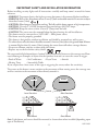
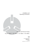
®
TM
Motion Sensing
Halogen Fixture
Model: SH-9525AU
Installation and Operating Instructions
FEATURES
•Automatically comes on when motion is detected.
•Automatically turns light off.
•Photocell keeps the light off during daylight
hours.
•LED indicates motion was sensed (day or
night).
REQUIREMENTS
•The light control requires 230 volts AC.
•If you want to use Manual Mode, the control
must be wired through a switch.
•It is illegal for persons other than a licensed
electrician or person authorized by legislation
to work on fixed wiring or other electrical
installations.
UNPACKING
Be sure to remove all contents from packaging
and verify all items are present before assembling
this light fixture. This package includes the following items:
•Security Light
•Canopy Extension with Rubber Gasket
•Rubber Plug
•Mounting Bolt
•Light Shield
•Owner’s Manual
Security Light*
*Note: Illustrations are for reference only and may
be different from actual product
Before installation, record the model number listed inside the fixture. Attach receipt
in case of possible warranty issues.
Model Number:
© 2011 The Chamberlain Group, Inc
201114-01A
IMPORTANT SAFETY AND INSTALLATION INFORMATION
Before installing security light, read all instructions carefully and keep owner’s manual for future
reference.
•WARNING: To prevent electric shock, please ensure that power is disconnected before installation.
•WARNING: Risk of fire. Keep fixture at least 51 mm (2") from combustible materials. Do not aim at objects
closer than 1 meter (3 feet).
1m
•CAUTION: Allow fixture to cool before touching. The bulb and the fixture operate at high temperatures.
• CAUTION: Use only T3, 250W (maximum) tungsten halogen 230 VAC lamps.
•CAUTION: Keep the sensor at least 25 mm (1") away from the bulb.
•CAUTION: The sensor must be mounted below the lamp housing for wall installations.
•This fixture must be connected to a 230V-240V ~ 50Hz power source.
•The fixture must be properly grounded.
•This fixture is designed for outdoor installation and should be mounted to a wall or eaves.
•To achieve best results, this fixture should be mounted 2.4 meters (8 feet) above the ground. Note: If fixture
is mounted higher than 2.4 meters (8 feet), aiming the sensor down will reduce coverage distance.
•Do not use dimmer switches or timers with this fixture.
•Replace any cracked or broken safety shield.
The sensor on this light fixture detects “motion” by the movement of heat across the coverage area. However, following are examples of objects that also produce heat and can cause the sensor to trigger:
• Pools of Water
• Air Conditioners • Dryer Vents • Animals
• Heating Vents
• Automobile Traffic
If you suspect that a heat source of this type is triggering the sensor, reduce the sensitivity.
The sensor on this fixture is more sensitive to the movement of heat moving across the coverage area
and less sensitive to the movement of heat directly towards it.
Motion
Least Sensitive
Wall Mount
Motion
Sensor
Most Sensitive
Eave Mount
Note: Light fixture and sensor should be mounted as shown above when installed (depending upon
type of installation).
201114-01
2
INSTALLATION
Canopy Extension
This light fixture must be installed by a
licensed electrician or other person authorized by legislation to work on fixed wiring
or other electrical installations.
UP
WARNING: Turn power off at circuit
breaker or fuse. Place tape over circuit
breaker switch and verify power is off at
the fixture.
IMPORTANT: Do NOT use with dimmers or
timers.
For best performance, mount the fixture about 2.4
meters (8 feet) above the ground. Note: If fixture is
mounted higher than 2.4 meters (8 feet), aiming
the sensor down will reduce coverage distance.
This fixture comes with a canopy extension. It is
pre-assembled on the fixture for shipping.
1. Remove the center mounting bolt connecting
the fixture canopy to the canopy extension (see
Figure 1). Note: Be sure rubber gasket is on
the canopy extension.
2. Place the canopy extension against the mounting surface and mark the positions for the
mounting screws (see Figure 2). Note: When
positioning the canopy extension for mounting,
do the following:
•Keep the mounting tabs level
•Make sure the canopy extension is turned
as shown in Figure 2
•Make sure the house wiring is located behind
or below the rubber grommet.
3. Use a power drill to drill into the wall to provide
a suitable mounting for the screws.
•Canopy extension mounting screws are not
included. Use 4mm dia. (8G) x 30mm screws.
•Care should be taken to avoid drilling or
screwing into concealed electrical wiring.
•For solid brick walls, screws and masonry
plugs should be used.
4. Make a small hole in the rubber grommet and
route the house wire through the hole (see
Figure 3).
5. Attach the canopy extension to the surface.
201114-01
Rubber Gasket
Mounting
Bolt
Fixture Canopy (Lamp
head and sensor not
shown for clarity)
Figure 1
Mounting Tab
L
N GND
UP
Figure 2
4mm dia. (8G)
x 30mm Screw
UP
Rubber
Grommet
House Wiring
3
Figure 3
WIRING
FINAL ASSEMBLY
1. Double check all wiring connections.
2. Verify the rubber gasket is properly seated
around the edge of the canopy extension (see
Figure 6).
3. Align the center hole on the fixture canopy
with the center hole on the canopy extension
and attach using the mounting bolt removed
in step 1 of Installation (see Figure 6).
IMPORTANT:
•If wall mounted, make sure the fixture is
mounted with the sensor below the bulb
holders.
•If eave mounted, mount the fixture with
sensor facing away from the house wall (see
Eave Installation Information for important
sensor orientation information).
4. Push the rubber plug firmly into place (see
Figure 7).
5. Caulk around top half of canopy extension
with silicone weather sealant (see Figure 7).
6. Install bulb. Do not exceed wattage rating on
fixture label.
WARNING: Turn power off at circuit
breaker or fuse. Place tape over circuit
breaker switch and verify power is off at
the fixture.
1. Connect the house wires to the terminal block
according to diagram (see Figure 4). Make
sure all screws on terminal block are tightened
securely.
2. Remove the strain relief cover and place the house
wires across the strain relief (see Figure 5).
3. Replace the strain relief cover and tighten
securely. Note: Be careful not to overtighten
and damage the wiring.
Terminal Block
From Fixture
From AC Source
Brown
Red or Brown
Blue
Blue or Black
Green/Yellow
Fixture Canopy (Lamp
head and sensor not
shown for clarity)
Green/Yellow
Figure 4
UP
Terminal Block
Rubber Gasket
Strain Relief
Cover
Mounting
Bolt
Screw
Figure 6
UP
House Wiring
Figure 5
4
201114-01
BULB INSTALLATION AND
REPLACEMENT
Caulk Upper Half of Canopy Extension
CAUTION: When replacing bulb, turn
power off and let the fixture cool.
Canopy
Extension
UP
Rubber Plug
Important: Use a clean glove or cloth when
handling the new bulb. Use isopropyl (rubbing)
alcohol to clean the bulb if it is touched with
your bare hands.
Figure 7
EAVE INSTALLATION
INFORMATION
NOTE: The bulb is included, but need to be
installed. The bulb is located behind the glass
cover of the lamp head.
1. Remove glass cover and remove the old bulb
by pushing the bulb towards the right until
the left side of the bulb is clear of the left
socket.
2. To install the bulb, place one end of the bulb on
the contact in the right socket. While pushing
the bulb against the right contact, lower the
other end of the bulb onto the contact in the
left socket.
3. Spin the bulb to verify it is seated properly.
4. Re-install the glass cover.
For proper operation and safety, the light
fixture must be above the sensor and the sensor head must be rotated so that the controls
are on the bottom.
IMPORTANT: For under eave installation only, the
sensor head must be rotated as shown in the next
two steps for proper operation and to avoid the
risk of electrical shock. For proper under-eave
operation, install light shield (included). See
Light Shield Installation for details.
1. Rotate the sensor head towards the clamp
screw joint (see Figure 8).
2. Then rotate the sensor head clockwise 180° so
the controls face down (see Figure 9).
Note: If the sensor pops out of the ball joint, loosen
the clamp screw and push the sensor back into the
ball joint. Tighten the clamp screw when done.
Controls
Clamp Screw
Bulb
Lamp Head
Left
Socket
Figure 8
1
Right
Socket
Controls
Contact
Light
Shield
2
Figure 10
Controls
201114-01
Figure 9
5
TESTING AND ADJUSTMENTS
4. Loosen the clamp
screw in the sensor
Clamp
ball joint and gently
Screw
rotate the sensor.
Ball
5. Walk through the
Joint
coverage area noting
where you are when
the lights turn on (also,
the LED will flash
several times when
Aim Sensor Down
motion is detected). In
for Short Coverage
TEST mode, light will
stay on for 5 seconds after motion has stopped
and then turn off.
Move the sensor head
Aim Sensor Higher
up, down, or sideways
for Long Coverage
to change the coverage
area. Keep the sensor
at least 2.5 cm (1") away from the bulbs.
6. Adjust the RANGE as needed. RANGE set
too high may increase false triggering due to
heat sources in the coverage area (see Troubleshooting section).
7. Secure the sensor head by tightening the clamp
screw. Do not overtighten the screw.
8. Set the amount of ON-TIME you want the
light to stay on after motion is detected (1, 5,
or 10 minutes). The timer will reset as long
as there is motion present. Once motion has
stopped, the timer will time-out after the
selected amount of time.
1. Turn on the circuit breaker and light
switch.
Note: Sensor has a 1 1/2 minute warm up period
before it will detect motion. When first turned
on wait 1 1/2 minutes.
2. Set:
•ON-TIME switch to TEST
•RANGE dial to Midway position
ON-TIME
RANGE
10 5 1 TEST
MINMAX
Bottom of Sensor
3. Adjust the lamp head by loosening the lock nut
or using a screwdriver. The lamp head must be
mounted horizontally (see Figure 11). After
positioning lamp head, tighten the lock nut
and apply thread sealant to ensure lamp head
does not rotate.
WARNING: Risk of fire. Do not aim the
bulbs at a combustible surface within 1
meter (3 feet).
1m
180°
2.4 m
(8 ft.)
RIGHT
21 m
(70 ft.)
Maximum
Maximum Range
Coverage Angle*
(Side View)
(Top View)
WRONG
The halogen light must be
mounted horizontally (+/- 4°).
Figure 11
6
201114-01
OPERATION
Mode:
Test
Auto
Manual
On-Time
5 Seconds
1, 5, or 10
Minutes
To Dawn*
LIGHT SHIELD INSTALLATION
If your light does not come on at dusk or turns
off unexpectedly, then another light source may
be activating the daytime shutoff feature. Possible
sources of light interference are street lights, landscape lighting, other security lights or lanterns, or
an interior house light shining through a window.
It could also be reflective light, such as from a pool
or light colored wall.
To install the light shield, follow these simple
steps.
1. Remove protective backing from the bottom
of the light shield.
2. Position light shield over the photocell with
the opening facing away from the interfering
light.
3. Press the adhesive side firmly against the
photocell to mount it permanently in place.
Works: Day Night
x
x
x
x
* resets to Auto Mode at dawn.
Note:When first turned on wait about 1 1/2 minutes
for the circuitry to calibrate.
MANUAL MODE
Manual mode only works at
night because daylight returns
the sensor to AUTO.
Flip the light switch off for one
second then back on to toggle
between AUTO and MANUAL
MODE.
Manual mode works only with
the ON-TIME switch in the 1,
5, or 10 position.
1 Second
OFF then...
Light
Shield
... back on.
MODE SWITCHING SUMMARY
TEST
AUTO
MANUAL MODE
ON-TIME Switch at 1, 5,
or 10 minutes
Flip light switch
off for one second
then back on*
* If you get confused while switching modes, turn
the power off for one minute, then back on. After
the calibration time the control will be in the AUTO
mode.
201114-01
7
Protective
Backing
SPECIFICATIONS
Range�������������������������������������������������Up to 21 m (70 ft.) [varies with surrounding temperature]
Sensing Angle������������������������������������Up to 180°
Electrical Load�����������������������������������Up to 250 Watt Maximum Halogen
Replacement Bulb������������������������������T3 250W (or less) halogen 230 VAC
Power Requirements��������������������������� 230 VAC, 50 Hz
Operating Modes�������������������������������TEST, AUTO, and MANUAL MODE
ON-Timer������������������������������������������ 1, 5, 10 minutes
Test Timer������������������������������������������ 5 Seconds
Manual Mode Timer�������������������������� Dusk-to-Dawn
Ingress Protection������������������������������� IP43
TROUBLESHOOTING GUIDE
SYMPTOM
POSSIBLE CAUSE
SOLUTION
Light will not come
on.
1.
2.
3.
4.
5.
6.
1.
2.
3.
4.
5.
6.
Light comes on in
daylight.
1. Light control may be installed in a relatively dark
location.
2. Light control is in TEST.
1. The fixture is operating normally under these
conditions.
2. Set ON-TIME switch to 1, 5, or 10 minutes.
Light comes on for
no apparent reason.
1. Light control may be sensing small animals or automobile
traffic.
2. Range is set too high.
1. Re-aim sensor. Reduce range.
Light stays on
continuously.
1. Bulb is positioned to close to the sensor or pointed at
nearby objects that cause heat to trigger the sensor.
2. The sensor may be picking up a heat source like an air
vent, dryer vent, or brightly painted, heat-reflective
surface.
3. Light control is in Manual mode.
4. Sensitivity is set too high.
1. Reposition the bulb away from the sensor or nearby
objects.
2. Re-aim sensor. Reduce range.
1. Heat or light from the bulb may be turning the light
control on and off.
2. Light control is in the TEST mode and warming up.
3. Heat being reflected from other objects may be affecting
the sensor.
4. If eave installation, light shield not installed properly.
1. Reposition the bulb away from the sensor.
Light flashes on
and off.
Light switch is turned off.
Bulb is loose or burned out.
Fuse is blown or circuit breaker is turned off.
Daylight turn-off is in effect.
Incorrect circuit wiring, if this is a new installation.
Light control aimed in wrong direction.
Turn light switch on.
Check bulb and replace if necessary.
Replace fuse or turn circuit breaker on.
Recheck after dark.
Verify wiring is correct.
Re-aim light control to cover desired area.
2. Reduce range.
3. Switch to Auto.
4. Reduce range.
2. Flashing is normal under these conditions.
3. Re-aim sensor. Reduce range.
4. Install light shield according to instructions.
The Chamberlain Group reserves the right to discontinue products and to change specifications at
any time without incurring any obligation to incorporate new features in products previously sold.
201114-01
8
CHAMBERLAIN LIMITED WARRANTY
Lighting and Chime Products
Chamberlain Australia Pty Limited / Chamberlain New Zealand Limited (Chamberlain) is committed to manufacturing and supplying high quality goods. As
part of this commitment, we seek to provide reliable service and support for our goods and are pleased to provide you, the original purchaser, with this Chamberlain
Limited Warranty.
We also provide the following statement as required by the Australian Consumer Law: In Australia, in addition to your rights under this Chamberlain Limited Warranty, our goods come with guarantees that cannot be excluded under the Australian Consumer Law. You are entitled to a replacement or refund for a major failure and
for compensation for any other reasonably foreseeable loss or damage. You are also entitled to have the goods repaired or replaced if the goods fail to be of acceptable
quality and the failure does not amount to a major failure.
Chamberlain’s warranty
Chamberlain warrants to the original purchaser of the lighting or chime product (including any LED lights which are provided by Chamberlain as part of the goods)
(Unit) that the Unit is free from defects in materials and workmanship for a period of 12 months from the date of purchase.
During the applicable Chamberlain Limited Warranty period, if you are concerned that the Unit may be defective, contact your retailer who will provide you with a
replacement Unit or refer you to our service centre for a factory repair or replacement.
If your retailer refers you to us, call our service centre on the toll free number below and a Chamberlain technician will diagnose the problem. Once the problem has
been diagnosed, subject to your rights under the Australian Consumer Law with respect to major failures, Chamberlain will provide you with shipping instructions
for a factory repair or replacement.
If a factory repair or replacement is required, provided the defective part or Unit is returned to Chamberlain well-packaged and in accordance with Chamberlain’s
shipping instructions, Chamberlain will repair or, at its option but subject to your rights under the Australian Consumer Law with respect to major failures, replace
any defective part or Unit and return it to you at no cost.
Repairs and replacement parts provided under this Chamberlain Limited Warranty are provided free of charge and are warranted for the remaining portion of the
original warranty period.
This Chamberlain Limited Warranty provides benefits which are in addition to your other rights and remedies as a consumer.
Exclusions
If our service centre determines that a warranty claim has been made in respect of a failure or defect arising under or out of any exclusion detailed below such that the
claim is not covered under this Chamberlain Limited Warranty, we may, subject to your other rights and remedies as a consumer, charge you a fee to repair, replace
and/or return the Unit to you.
Exclusions
This Chamberlain Limited Warranty does not cover any failure of, or defect in, the Unit due to:
1. non-compliance with the instructions regarding installation, operation, maintenance and testing of the Unit or of any product with which the Unit is used;
2. any attempt by a person other than an authorised installer to repair, dismantle, reinstall or move the Unit to another location once it has been installed;
3. tampering, neglect, abuse, wear and tear, accident, electrical storm, excessive use or conditions other than normal domestic use;
4. problems caused by electrical faults or replacement of batteries or light bulbs;
5. submersion in water or other fluids;
6. power supply greater or less than what is specified;
7. use of a light bulb with a higher wattage than that specified; or
8. for chimes products, radio interference from another radio frequency appliance.
If this Chamberlain Limited Warranty does not apply, you may have rights available to you under the Australian Consumer Law.
Liability – Australia only
Except as set out in the Australian Consumer Law (being Schedule 2 of the Competition and Consumer Act 2010) (as amended, consolidated or replaced):
1. all other guarantees, warranties and representations in relation to the Unit or its supply are excluded to the extent that Chamberlain can lawfully exclude them;
and
2. under no circumstances will Chamberlain be liable for consequential, incidental or special damages arising in connection with the use, or inability to use, the Unit,
other than those which were reasonably foreseeable as liable to result from the failure.
Liability – New Zealand only
Except as set out in the Fair Trading Act 1986 and the Consumer Guarantees Act 1993 (as amended, consolidated or replaced):
1. all other guarantees, warranties and representations in relation to the Unit or its supply are excluded to the extent that Chamberlain can lawfully exclude them;
and
2. under no circumstances will Chamberlain be liable for consequential, incidental or special damages arising in connection with the use, or inability to use, the Unit,
other than those which were reasonably foreseeable as liable to result from the failure.
Note
We request that you retain your sales docket or invoice as proof-of-purchase and attach it to this manual to enable you to establish the date of purchase in the unlikely
event of a warranty service being required. Chamberlain reserves the right to change the design and specifications of the Unit without prior notification. Some features
or accessories of the Unit may not be available in certain markets or areas. Please check with your retailer.
Chamberlain service centre contact details
Australia
New Zealand
Phone toll free 1800 638 234
Auckland phone 09 477 2823
Fax toll free 1800 888 121
Phone toll free 0800 653 667
Email: [email protected]
Fax toll free 0800 653 663
Chamberlain Australia Pty. Ltd.
Chamberlain New Zealand Limited
Unit 3, 7-9 Orion Rd
17A Arrenway Drive, Albany
Lane Cove NSW 2066
Auckland
(P.O. Box 1446, Lane Cove, NSW 1595)
(PO Box 100221 North Shore 0745)
Website
www.chamberlainanz.com
201114-01
9
NOTES__________
________________
________________
________________
________________
________________
________________
________________
________________
10
201114-01
NOTES__________
________________
________________
________________
________________
________________
________________
________________
________________
201114-01
11
NOTES__________
________________
________________
________________
________________
________________
________________
________________
________________
12
201114-01