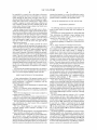
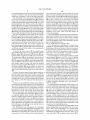
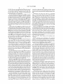
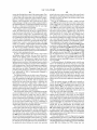
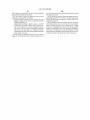
1
USOO7915570B2
(12) United States Patent
(10) Patent N0.:
Cetrulo et a].
(45) Date of Patent:
(54) SMART CAMERA WITH AN INTEGRATED
2
,
LIGHTING CONTROLLER
_
(75)
Inventors: Raffaele A. Cetrulo, Aust1n, TX (US);
William M. Allai, Austin, TX (U S);
-
'
.
Assignee: National Instruments Corporation,
A t- TX (Us)
Notlce:
_
_
2/2003
8/2003 Ulrich et 31‘
9/2005 Fielden et al.
_
Paulsen et a1.
Ulrich et a1.
2/2007 Roberge et a1.
7,259,522 B2
8/2007 Toyota et al.
7,331,681 B2
7,397,550 B2
2/2008 POhleIT et 31~
7/2008 Hackney et al.
2005/0236998
Subject to any d1scla1mer, the term of th1s
patent is extended or adjusted under 35
A1
7/2004
10/2005
2006/0032921 A1
Thibaud et al. ............. .. 250/205
Mueller et al.
2/2006 Gerst, 111 @131,
OTHER PUBLICATIONS
“Legend 540”; DVT Machine Vision; 2004; 2 Pages.
“PresencePLUS Vision Sensors”; Second Edition; Banner Engineer
Appl. N0.: 12/184,931
(22) Filed;
10/2005
1
10 eta .
6,522,777 B1
U.S.C. 154(b) by 368 days.
(21)
1cc
6,603,103 B1
6,950,196 B2
2004/0129860 A1 *
_
ethql
occ
3/2001 Jusoh et al.
7,178,941 B2
us In,
(*)
I‘ll;
,
6,963,175 B2 10/2006
11/2005 Gladnick
Archenholdet a1.et a1.
7,127,159 B2
Nlcolas Vazquez, Austln, TX (US)
_
Mar. 29, 2011
6,207,946 B1
6,956,963 B2
3n“?
2211110}:
Aufin?s T1? FEES),(U S )’_
f‘n“ aw, 011“ _ 0° ’
(73)
US 7,915,570 B2
ing Corp.; 2005; 36 Pages.
“Cognex Checker”; Cognex Corporation; 2005; 6 Pages.
Aug_ 1, 2008
“Cognex DVT LineScan Users Guide”; Cognex Corporation; 20
-
(65)
-
-
Pages; Accessed from Internet Jan. 15, 2009; http://www.c0gnexsen
Pnor PUbhcatlon Data
US 2009/0033761 A1
sors.com/support/DownloadsManager.php?Order:Index&
Feb. 5, 2009
KW:DVT%20MaIlua1#~
“Cognex MVS-8000 Series: MVS-8100L Hardware Manual”;
Related U_s_ Application Data
Cognex Corporation; Oct. 2006; 40 Pages.
(60) Provisional application No. 60/953,889, ?led on Aug.
3, 2007.
(continued)
Primary Examiner * Thanh X Luu
(51)
Int. Cl.
(74) Attorney, Agent, or Firm * Meyertons Hood Kivlin
G01J1/32
H053 37/02
(52)
(58)
(2006,01)
(2006.01)
Kowert & Goetzel, P.C.; Jeffrey C. Hood
us. Cl. ...................................... .. 250/205; 315/308
Field of Classi?cation Search ................ .. 250/205;
315/308
(57)
ABSTRACT
A smart camera includes an integrated lighting current con
troller and can couple to one or more external light sources.
See application ?le for complete search history.
The integrated lighting current controller can control and
power the one or more external light sources using a current
(56)
References Cited
pulse. The one or more external light sources can provide
illumination for the smart camera to acquire the image of an
US. PATENT DOCUMENTS
5,134,469 A *
5,172,005 A
7/1992
object under test.
Uchimura ..................... .. 348/68
25 Claims, 11 Drawing Sheets
12/1992 Cochran et al.
Smart Camera 111]
FPGA M
I— — — — — — —
E
750
_
Input
758
User Light
.
Timing
Settings 1
79
_ _
_ _
_ _
_ _
_ _
_ _
_ _
_ _
_ _
— — — -|- - — — -
I
_ _
_ _
_ _ _ _,
Lighting Controller LQQ I
.
=
'
m
|
|
I
I
|
|
|
(752 |WW7I
Generation
M
I
00,"
am
l
I
l
|
I
38mm
Generation
:
1L4
|
i
1
|
:
:
Ligsht‘Curr’enl l
e pain
I
I
l
US$760
I
Genera?on
Programmed
|
m
Lighlcorrent
|__________ _ _'____'l__“_'l'____'l'_“_'l___ 4
sew"?
: l— 756
l
'
L
I
:
_
1'
Processor Executing
er.
Algorithm Sequence
12:1
Inspection
Pass/Fail
Result
US 7,915,570 B2
Page 2
OTHER PUBLICATIONS
“PD2-1012iPD2 Series Digital Type”; CCS; 2006; Accessed from
Internet at http://WWW.ccs-inc.cojp/cgi-bin/hp.cgi?menu:102-201
“Installing the In-Sight 3000”; CogneX Corporation; 2002; 43 Pages.
“In-Sight Strobe Light Adapter Installation & Reference”; CogneX
Corporation; 2002; 18 Pages.
“Tech Note: Connecting a Strobe Device to the In-Sight 1000 and
4000 Series Vision Sensors”; CogneX Corporation; 2003; 12 Pages.
“SmaItImage Sensor Installation and User Guide, 7th Edition”; DVT
02-0 1 e.
“PS-3012-D24 Strobe Power Supply”; CCS; 2006; Accessed from
Internet at http://WWW.ccs-inc.cojp/cgi-bin/hp.cgi?menu:102-201
10-0 1 e.
“CogneX Product Guide 2007”; CogneX Corporation; 2007; 10
Pages.
Corporation; Aug. 2003; 157 Pages.
“FrameWork”; DVT Corporation; 2004; 2 Pages.
“Modular Lighting Controller (MLC)”; ETS-Lindgren; 2003; 2
“App 909iPP600 Heat Output”; Gardasoft Vision; 2003; 2 Pages.
“PP500 RangeiLED Lighting Controller With Ethernet Interface”;
Gardasoft Vision; 2006; 2 Pages.
“PP600 Series LED Lighting Controller” Gardasoft Vision; 2003; 2
Pages.
Pages.
“PP600iLED Lighting Controller for NERLITE MV Lighting
“The PP860 Series High Current LED Lighting Controllers”;
Gardasoft Vision; 2006; 2 Pages.
“Gardasoft Vision User MmualiPPSOO, PP520, PP500F, PP520F
LED Lighting Controllers”; Revision 08; Gardasoft Vision; 2007; 28
Components”; Siemens; 2003; 2 Pages.
“Installation of TPS-28 Universal Lighting Power Supply”; Execu
tive Engineering; May 2004; 25 Pages.
“Signatech Intensity Controller Manual MS210 / MS220 / CS410 /
CS420”; Advanced Illumination; Feb. 2006; 18 Pages.
Pages.
“Gardasoft Vision User ManualeP600, PP602, PP610, PP612
LED Lighting Controllers”; Revision 13; Gardasoft Vision; 2006; 32
“Pulsar 710 Controller Operator’s Manual & Installation Guide”;
Advanced Illumination; Oct. 2005; 40 Pages.
“Signatech Controller Manual S4000 / S6000 / S6000-AS”
Advanced Illumination; Oct. 2006; 17 Pages.
“GardasoftVision User ManualeP600F, PP602F, PP610F, PP612F
LED Lighting Controllers”; Revision 10; Gardasoft Vision; 2003; 32
“Application NoteiPP860 Heat Output”; GardasoftVision; Sep. 29,
2006; l Page.
“Application NoteiPP500 Heat Output”; GardasoftVision; 2003; 2
NERLITE MV Lighting Components”; Siemens; 2003; 2 Pages.
Pages.
Pages.
“SCM Strobe Control Module”; Banner Engineering Corp.; May
2001; 4 Pages.
Pages.
Pages.
“PP610iLED Lighting Controller With RS232 Control for
“NERLITE SCM-l Strobe Control Module, IVUD”; Siemens; 2003; 2
* cited by examiner
US. Patent
Mar. 29, 2011
Sheet 1 0f 11
US 7,915,570 B2
Em25u:8tug2s
N2£9562
we
F
5c:o?8c2i
1/9:
2
F
@268%
v.QIE:$25$5
US. Patent
Mar. 29, 2011
Sheet 2 0f 11
US 7,915,570 B2
1021‘
1 10 —\
Sma? Camera
192
JEEEEEEEEQEEEQ
W
@
%W@
,
w
@
FIG. 2A
110-\
Sma? Camera
192
JEEEEEEEE“®®®®\
@Y
@2
@6061@
Y9)
Y9
US. Patent
Mar. 29, 2011
US 7,915,570 B2
Sheet 4 0f 11
8ESQ O 29$g
:GEmeS
1H;
$5 $250 3
US. Patent
Mar. 29, 2011
Sheet 5 0f 11
US 7,915,570 B2
"FIG.4A
IEtxhp/earnOsiton
Software
192
I/ODirect
Lens
280
SLioguhrtcieng
FiCxatmuera
Enclosure
US. Patent
Mar. 29, 2011
Sheet 6 0f 11
FIG. 4C
US 7,915,570 B2
US. Patent
Mar. 29, 2011
Sheet 7 0f 11
US 7,915,570 B2
2520 .2
m0,me
_g_I
I_g0520:02_00
O20.6:0
?
n
Ig00082_
2\0WWW
[email protected] :82m02
0.03
g__|
_
_
_|_E5tFS0E.5I0
0.5|0ch
_
I<02?_
nmm0Fn20 025;02
__03.0 25
,$025me0
4/0:
_0I2 02 1 mII4o_Im8502h0m8:é|_gI 1| |
_
m
_02 90 2 _$005I_
_025m0_2m0 00m_00w_
@_08I02
$d20aQ§5>E0
.GI<6
US. Patent
Mar. 29, 2011
US 7,915,570 B2
Sheet 9 0f 11
S3m5u8cg3i$:55BEm=u§<1Mm¢QwS§m58N=%3S$»m?IQ
|n
_
_
_
_
n
_
a
_=
_
“
_
_2&8
sq:
w\la$88:25
_
H
_
Q:
E
_
_
Egon_H_mm“I.
at:55
511%
»m
o?|
1_
:_91\
3at_
8 \QQQa
"1%
5:3:
@250
1_
1_1
+1
SE:_EgoQQEmw
1"
__
$3_wson“
Em:
pam4/
1cg_sn
oEn
__
Essmm
_
"
om“H
1\
_§
1_
“1E_ESQEQ
_QRcg_Em:zm_w |
coh?mwmw
EEG2g
g
=21
$35
E58_
H1__1
W1Em:El_HI21.-H3l101l
1l1?
E$8mgu
\
_m_gQEsNSmQwEQE
w
u_32F1GNE%._9:1sz
m$32m=é<
2.? a
§5%DEu
E?w
$925%
US. Patent
Sheet100f11
B4ar.29,2011
wowk
Al 6:20
bmoq
Bmco
NW
\
N
EmtMso
mum2
US 7,915,570 B2
US 7,915,570 B2
1
2
SMART CAMERA WITH AN INTEGRATED
LIGHTING CONTROLLER
factors such as ambient light conditions and required expo
sure time. Existing lighting current controllers generally use
PRIORITY CLAIM
Various existing approaches to use light sources with a cam
linear power supply designs which are bulky, heavy, and hot.
era in machine vision/ image processing applications are
described below. Examples of lighting controllers include
This application claims priority to provisional patent appli
Camera Lighting Circuit with High Power Density and Long
BANNER PRESENCE and SCM products, ETS
LINDGREN MODULAR LIGHTING CONTROLLER,
Strobe Intervals,” to Cetrulo et al., ?led on Aug. 3, 2007.
ADVANCED ILLUMINATION SIGNATECH S4000/6000
cation No. 60/ 953 ,889 titled “New Architecture for Industrial
and PULSAR products, SIEMENS PP610 product, and
GARDASOFT PP420 product, among others.
FIELD OF THE INVENTION
A ?rst approach may use an external lighting current con
troller along with an external power supply. This approach
works well but requires additional and external components,
The present invention relates to the ?eld of machine vision,
and more particularly to a smart camera with an integrated
lighting current controller.
e. g., an external lighting current controller, and sometimes an
additional power supply. Furthermore, if the lighting current
DESCRIPTION OF THE RELATED ART
In many applications, machine vision or image processing
analysis is used to inspect or locate an object. For example, in
controller and/ or the power supply use regular linear power,
then the power draw and/or heat dissipation may become an
issue and may need bigger power supplies and/ or heat dissi
20
manufacturing applications, machine vision analysis may be
may be undesirable due to added complexity and cost, as well
as additional reliability issues.
used to detect defects in a manufactured object by acquiring
images of the object and using various types of image pro
cessing algorithms to analyze the images. As an example, a
system to manufacture electrical components such as capaci
Another approach may utilize integrated lights, such as
LED’s or other light sources, built into a smart camera. How
25
tors may use machine vision to examine respective sides of
ensure that the capacitors are labeled, marked, or color coded
30
the manufacturer, this approach does not solve the user’s
application.
Furthermore, the built-in lighting solutions mainly use a
35
cameras, line scan cameras, infrared imaging devices, x-ray
imaging devices, ultra-sonic imaging devices, and any other
type of device which operates to receive, generate, process, or
acquire an image or sensor data.
Typically, the image processing and analysis of image data
ability to directly control and/ or power external light sources.
As a result, if the user’s illumination requirements can not be
met by the limited selection of integrated lights provided by
era or other device may be used to acquire the images to be
analyzed in a machine vision application, including digital
ever, the integrated lights on a smart camera (e.g., integrated
illumination) do not provide the quality and intensity and
variety of con?gurations needed for many machine vision
applications. Systems with integrated lights do not have the
the capacitors in order to detect manufacturing defects,
properly, etc.
Machine vision applications may use image processing
software operable to perform any of various types of image
analysis or image processing functions or algorithms in
examining an acquired image of an object. Any type of cam
pation devices. Some heat dissipation devices, such as fans,
40
is performed by a computing system which may be coupled to
the camera. Increasingly, however, such image processing
voltage signal to control and power the built-in LED(s). The
brightness of an LED is usually controlled by the amount of
current through the LED. Using an unregulated or regulated
voltage signal that is, by some mechanism, converted to cur
rent is not accurate, and precludes the possibility of overdriv
ing the LED(s) in a strobing application.
SUMMARY OF THE INVENTION
capabilities are performed by the camera or sensor by hard
Various embodiments of a smart camera system with an
ware and/ or software “on-boar ” the device. The term “smart
camera” is intended to include any of various types of devices
45
integrated lighting current controller are presented below. In
that include a camera or other image sensor and a functional
some embodiments, the smart camera may comprise a pro
unit (i.e., a processor/memory and/or programmable hard
ces sing unit, imager, memory, and an integrated (i.e., built-in)
ware, such as a ?eld programmable gate array (FPGA))
lighting current controller. The smart camera may include a
capable of being con?gured to perform an image processing
housing containing all the elements of the smart camera. The
smart camera may also use a built-in imager for image acqui
sition, or alternatively it may connect to an external imager/
function to analyze or process an acquired image. Examples
of smart cameras include: NAVSYS Corporation’s GI-EYE,
50
which generates digital image data that are automatically
tagged with geo-registration meta-data to indicate the precise
position and attitude of the camera when the image was taken;
Vision Components’ GmbH Smart Machine Vision Cameras,
lens/ camera for analog or digital image acquisition.
The integrated lighting current controller may be operable
55
which integrate a high-resolution Charge Coupled Device
lights. The lighting current controller may be able to strobe
the lights substantially aron the time of the exposure, and
possibly right before the exposure, such that the unit under
test has the desired lighting when the exposure is taken.
(CCD) sensor with a fast image-processing signal processor,
and provide various interfaces to allow communication with
the outside world; and Visual Inspection Systems’ SMART
cameras with on-board DSP capabilities, including frame
to couple to one or more external light sources, which may be
regular of-the-shelf lighting sources such as LED’s or other
60
The lighting current controller uses a switching power
grabbers and robot guidance systems, among others.
Lighting controllers may be used to power lightheads (light
sources) that provide illumination of objects to be imaged.
limited power dissipation, it can be integrated into the smart
Lighting controllers can use either voltage or current to con
the light source by generating a current pulse from the switch
trol and power light sources. Lighting current controllers can
provide either continuous or strobed current at variable cur
rent levels as required for the application, determined by
supply that minimizes power dissipation, and because of its
camera. The lighting current controller can control and power
65
ing power supply (while in the active state). The switching
power supply may receive a pulse-width-modulated (PWM)
signal that controls it output, and the PWM signal itself may
US 7,915,570 B2
3
4
be controlled by a control loop on the input on the power
supply. During intervals when it is desirable not to send any
current through the light source, the light source may be
contrary, the intention is to cover all modi?cations, equiva
lents and alternatives falling within the spirit and scope of the
present invention as de?ned by the appended claims.
disconnected from the output of the switching power supply.
During these intervals the switching power supply cannot
DETAILED DESCRIPTION OF THE INVENTION
continue to regulate its current output unless a dummy load
were connected and thus provide an alternate path for the
current output. However, using a dummy load would waste
power and increase heat output.
Instead, during intervals when the light source is discon
Incorporation by Reference
The following references are hereby incorporated by ref
erence in their entirety as though fully and completely set
forth herein:
Provisional US. Patent Application No. 60/953,889 titled
“New Architecture for Industrial Camera Lighting Circuit
nected, the switching power supply may be turned off. Since
these intervals are unknown (may be short or long depending
on the application) and since during this time the switching
power supply is not operating, the values of the components
in the control loop may decay with time. Once the control
with High Power Density and Long Strobe Intervals,” to
Cetrulo et al., ?led on Aug. 3, 2007.
US. Pat. No. 7,327,396 titled “Smart Camera with Modu
lar Expansion Capability,” to Schultz et al., issued on Feb. 5,
loop/switching power supply is inactive, the power supply
may take a while to reach the active state again with the
desired current accuracy.
Thus an active circuit can sample and hold the control
values, and thus provide the necessary fast response time to
achieve full current accuracy. This can be implemented using
2008.
20
FIG. 1 illustrates an image acquisition system in which a
host computer system 102 is coupled to a smart camera 110.
As used herein, the term “smart camera” is intended to
include any of various types of devices that are operable to
a microcontroller having ADC (analog-to-digital converter)
and PWM (pulse width modulation) capabilities. With the
active circuit, a memory of the control variables can be main
tained from when the control loop was regulating the output
25
acquire and/or store an image and which include on-board
processing capabilities. A smart camera may thus be further
operable to analyze or process the acquired or stored image.
Examples of a smart camera include analog and digital cam
eras with on-board processors, and other similar types of
30
devices. The smart camera may also include all the elements
shown in FIGS. 5-7 without the chassis. Thus the smart cam
era may be built into a custom chassis at a later time.
As used herein, the term “functional unit” may include a
processor and memory or a pro grammable hardware element.
current. The active circuit memory enables the lighting cur
rent controller to keep the control loop in an inactive state, and
ready for a quick return from the inactive state to the active
state, thus providing the desired current signal. As a result, the
integrated lighting current controller may be operable to con
trol the one or more external light sources using a current
signal to provide illumination for acquisition of an image of
an object.
It is noted that the examples presented above are meant to
be illustrative only, and are not intended to limit the function
ality or use of the integrated lighting current controller.
FIG. liImage Acquisition or Machine Vision System
35 The term “functional unit” may include one or more proces
sors and memories and/ or one or more programmable hard
ware elements. As used herein, the term “memory medium”
BRIEF DESCRIPTION OF THE DRAWINGS
A better understanding of the present invention can be
includes a non-volatile medium, e.g., a magnetic media or
40
obtained when the following detailed description of the pre
ferred embodiment is considered in conjunction with the
following drawings, in which:
FIG. 1 illustrates various embodiments of a general image
acquisition system;
45
FIGS. 2 A-C illustrate various embodiments of an image
hard disk, optical storage, or ?ash memory; a volatile
medium, such as SDRAM memory.
Thus, FIG. 1 illustrates an exemplary image acquisition or
machine vision system 100, where the smart camera 110 may
include a functional unit for performing an image processing
function as described below. The smart camera 110 may
include one or more function modules 108 which may pro
vide various additional functions for the smart camera as will
acquisition/processing system for inspecting manufactured
be described below. The smart camera 110 may couple to the
objects;
host computer 102 through a serial bus, a network, or through
FIGS. 3A-B are diagrams of a smart camera coupled to a
computer system via a network.
other means.
50
The host computer 102 may comprise a CPU, a display
FIGS. 4A-C are illustration of various components that can
connect to a smart camera with an integrated lighting current
mouse or keyboard as shown. The computer 102 may operate
controller, according to some embodiments of the invention;
with the smart camera 110 to analyze, measure or control a
FIG. 5A-B illustrate exemplary block diagrams illustrating
some embodiments of a smart camera with an integrated 55
device or process 150. Alternatively, the computer 102 may
be used only to con?gure a functional unit in the image
lighting current controller;
acquisition device or one or more of the function modules
screen, memory, and one or more input devices such as a
108. In other embodiments, the computer 102 may be omit
ted, i.e., the smart camera 110 may operate completely inde
FIG. 6 is a block diagram of a smart camera with an
integrated lighting current controller, according to one
embodiment; and
FIGS. 7A-B are block diagrams of an integrated lighting
current controller, according to some embodiments.
While the invention is susceptible to various modi?cations
and alternative forms, speci?c embodiments thereof are
shown by way of example in the drawings and are herein
described in detail. It should be understood, however, that the
drawings and detailed description thereto are not intended to
limit the invention to the particular form disclosed, but on the
pendent of the computer.
60
The image acquisition system 100 may be used in a manu
facturing assembly, test, measurement, automation, and/or
control application, among others. For illustration purposes, a
65
unit under test (UUT) 150 is shown which may be positioned
by a motion control device 136 (and interface card 138), and
imaged and analyzed by the smart camera 110. It is noted that
in various other embodiments the UUT 150 may comprise a
process or system to be measured and/ or analyzed.
US 7,915,570 B2
6
5
back sides. Therefore, the smart camera 110 may include a
The smart camera 110 may include a memory medium on
housing having a plurality of sides and a lens directly attached
to the housing for acquiring an image of an object. In some
which computer programs, e. g., text based or graphical pro
grams, may be stored. In other embodiments, con?guration
information may be stored which may be used to con?gure a
programmable hardware element, such as a ?eld program
embodiments, the smart camera may also include all the
mable gate array (FPGA), comprised in the smart camera (or
chassis and/ or the imager/lens. Thus the smart camera may be
a function module, or the computer) to perform a measure
built into a custom chassis at a later time and may use a
ment, control, automation, or analysis function, among oth
custom and/ or external imager/lens.
As FIG. 3B also shows, the smart camera 110 may include
a chassis which includes a plurality of expansion slots for
elements shown in FIGS. 5A-B, 6, and 7, but without the
ers.
The host computer 102 may also include a memory
medium on which computer programs may be stored. In one
embodiment, another memory medium may be located on a
second computer which is coupled to the smart camera 110 or
to the host computer 102 through a network, such as a local
area network (LAN), a wide area network (WAN), a wireless
receiving function modules 108. The function modules 108
may thus provide a mechanism for expanding the capabilities
of the smart camera 110 in a modular fashion, such as
described in US. Pat. No. 7,327,396. In some embodiments,
the chassis does not contain any slots for the function mod
ules.
FIGS. 4 A-CiConnectivity Options of a Smart Camera
network, or the Internet. In this instance, the second computer
may operate to provide the program instructions through the
FIGS. 4A-C illustrate some embodiments of various con
network to the smart camera 110 or host computer 102 for
execution.
FIGS. 2 A-CiImage Processing Systems
nectivity options of a smart camera with an integrated lighting
20
module. It is noted that the smart camera 110 illustrated in
FIGS. 2 A-C illustrate image processing or machine vision
systems 500 according to various embodiments of the inven
FIGS. 4A-C is meant to be exemplary only, and is not
tion. The image processing system of FIG. 2A may comprise
any particular embodiment.
a computer 102 and a smart camera 110, and may further
include an actuator (e.g., a motion control device) 192. In one
intended to limit the form or function of the smart camera to
As indicated in FIG. 4A, in some embodiments, the smart
25
embodiment, the image processing system of FIG. 2B may
comprise smart camera 110 and motion control device 192,
and may not include computer system 102.
The smart camera 110 may include a digital camera that
acquires a digital video signal which comprises an image, or
30
a sequence of images, or other data desired to be acquired. In
one embodiment, the smart camera 110 may instead include
an analog camera that acquires an analog video signal, and the
35
particular application.
40
smart camera 110, according to some embodiments. FIG. 4B
shows how an external lighting current controller 622 may be
used in conjunction with the smart camera 110. The smart
camera may also include one or more ports (not shown) for
FIGS. 4B and 4C show various connectivity options for a
The smart camera 110 may include a lighting current con
troller allowing it to directly connect to one or more lighting
sources 606. In some embodiments, only one lighting source
is used to illuminate a part being examined. In some embodi
ments, multiple lighting sources are used to illuminate a part
612, an external power supply 614, Ethernet expansion I/O
616, operator interface 618 (such as for Human-Machine
Interface HMI), and/ or software 620, among others. The abil
ity to connect one or more off-the-shelf lighting sources 606
allows the user of the smart camera to directly connect anduse
various light sources available on the market as needed for the
smart camera 110 may further include A/D converters for
converting the analog video signal into a digital image.
camera 110 may be able to connect to various devices, such as
a lens 280, one or more off-the-shelf lighting sources 606, a
camera ?xture 608 for mounting the smart camera 110, an
enclosure 610 such as an all-weather enclosure, direct I/O
being examined, such as three separate lighting sources that
connections with one or more external lighting current con
provide Red, Green, and Blue (RGB) illumination. As
explained below, the lighting current controller may be oper
trollers and/or external power supplies. Also, an external
power supply 614 may be used in order to adequately power
able to pulse the one or more lighting sources such that the
the one or more external lighting sources 606. In some
one or more lighting sources are turned on only for duration of
embodiments the smart camera may be able to synchronize
the actual exposure of one or more images by the smart
camera 110. In some embodiments, the lighting current con
timing of the integrated universal current controller with tim
ing of the external lighting controller. For example, the FPGA
and/or the processing unit may ensure that the integrated
lighting controller and any external lighting controller are
troller may provide a continuous current to the one or more
lighting sources instead of a current pulse.
In the embodiments of FIGS. 2 A-C, the functional unit in
50
the smart camera 110 (or the computer system 102) may
control the actuator 192. Examples of motion control func
tions include moving a part or object to be imaged by a
able to illuminate one or more UUT’ s using proper timing for
a desired exposure interval.
FIG. 4C shows how the smart camera 110 with an inte
grated lighting current controller 290 may be used to directly
camera, rejecting a part on an assembly line, or placing or
af?xing components on a part being assembled, or a robotics
connect to one or more lighting sources 606, without the need
55 to use either an (additional) external power supply 614 or an
application, among others.
FIGS. 3 A-BiImage Acquisition System Having a Smart
external lighting current controller 622. The solution shown
Camera
FIGS. 3 A-B illustrate an image acquisition system with a
in FIG. 4C thus eliminates external hardware elements to save
smart camera 110. The smart camera 110 may include a 60
space, power, and cost that can be incurred by using the
external hardware elements.
FIG. 5A-BiSmart Camera Block Diagram
housing which encloses a portion or all of the smart camera
110 components, or may be comprised on a frame which
programmable hardware. As may be seen, this embodiment
primarily provides structural support for the smart camera
uses a combination of processor/memory 212/214 and pro
FIG. 5A is a block diagram of a smart camera 110 with
110 components. In some embodiments, a lens may be
attached directly to the housing. In one embodiment, the
housing may have a plurality of sides. For example, the plu
rality of sides may comprise top, bottom, left, right, front and
65
grammable hardware 206, e.g., FPGA, to perform image
processing (and/or other) functions. For example, the pro
grammable hardware 206 element in the smart camera 110
may be con?gurable to perform an image processing function
US 7,915,570 B2
7
8
on an acquired image. It should be noted that this embodiment
is meant to be illustrative only, and is not intended to limit the
architecture, components, or form of the smart camera 110.
The embodiment of the smart camera 110 illustrated in
FIG. 5A may include an imager 282 and a lens 280. The smart
camera may also include a functional unit 106, which may
comprise a programmable hardware element 206, e.g., a ?eld
vision system and the smart camera described in previous
?gures is that the embedded vision system does not necessar
ily include a built-in imager 282/lens 280. Instead, the embed
ded vision system may couple to an external imager 282/ lens
programmable gate array (FPGA), and may also comprise a
contain an imager 282, image memory 284, a lens 280, and a
processor 212 and memory 214. The programmable hardware
element 206, processor 212 and memory 214 may each be
coupled to the imager 282 and/or to an image memory 284.
images back to the embedded vision system. If the external
280 in order to acquire one or more images. The external
camera/lens may be a digital camera or it may be an analog
camera. If the external camera is a digital camera, then it may
digital bus interface to connect to and send one or more digital
The smart camera 110 may also include non-volatile memory
camera is an analog camera, then it may contain an analog bus
interface to connect to and send analog images back to the
288 coupled to the programmable hardware element 206, the
processor 212, the memory 214 and the image memory 284.
received analog images.
embedded vision system, which would then digitize the
The smart camera 110 may also include an T/O connector
In some embodiments, the lighting current controller inte
220 which is operable to send and receive signals. The T/O
connector 220 may present analog and/ or digital connections
grated into the embedded vision system operates in substan
tially similar manner to that of a smart camera, including
for receiving/providing analog or digital signals. For example
providing one or more current signals and/or pulses to one or
more external lighting sources as may be needed by the user
the T/O connector 220 may enable the smart camera 110 to
communicate with computer system 102 (such as the com
puter system shown in FIG. 3) to receive a program for
20
performing image processing (and/or other) functions. The
FIG. 6 illustrates some embodiments of a smart camera
including an integrated lighting current controller. In this
smart camera 110 may include a dedicated on-board proces
sor 212 and memory 214 in addition to the programmable
hardware element 206.
As shown, the smart camera 110 may include image
and/or an application program.
FTG. 6iBlock Diagram of a Smart Camera
block diagram various other elements of the smart camera are
25
memory 284 which couples to the programmable hardware
206, the imager 282, the processor 212, memory 214, bus
interface 216, the control/data bus 218, and a local bus 217.
The image memory 284 may be operable to store a portion of
not shown (such as of FIGS. 5A-B) for reasons of simplicity.
It should be noted that this embodiment is meant to be illus
trative only, and is not intended to limit the architecture,
components, or form of the smart camera 110.
In some embodiments, the smart camera 110 may include
30 a processing unit 206 such as an FPGA, as well as a lighting
current controller 290. The smart camera 110 may also con
an image, or one or more images received from the imager
282. The image memory 284 may enable the programmable
tain two or more lighting current controllers 290, where each
hardware 206 and/or the processor 212 to retrieve the one or
controller can connect to, control, and power multiple light
more images, operate on them, and return the modi?ed
images to the image memory 284. Similarly, one or more of
the function modules 108 may be operable to retrieve the
sources. The smart camera 110 may also contain a lens (not
35
image from the image memory 284, operate on the image, and
return the (possibly) modi?ed image to the image memory
284.
As shown, the smart camera 110 may further include bus
interface logic 216 and a control/data bus 218. In one embodi
ment, the smart camera 110 and/or a function module 108
may comprise a PCT bus-compliant interface card adapted for
coupling to the PCT bus of the host computer 102, or adapted
for coupling to a PXT (PCT eXtensions for Tnstrumentation)
40
smart camera 110. In some embodiments, the smart camera
45
FIGS. 5A and 5B.)
As shown, in one embodiment, the smart camera 110 may
50
ing signals between the smart camera 110 and one or more
other devices or cards, such as other smart cameras 110,
actuators, smart sensors, and/ or lighting current controllers.
In some embodiments, the smart camera 110 may contain
choosing a proper lighting source for the machine vision
application. In some embodiments the universal lighting cur
rent controller may be able to automatically sense the current
signal requirements necessary for the connected one or more
light sources. In some embodiments a user may need to indi
60
cate to the smart camera the type and/ or requirements of the
connected one or more lighting sources.
The analog image data created by the imager 282 and/or an
below with respect to FIGS. 6-8.
FIG. 5B illustrates some embodiments of an embedded
vision system with an integrated lighting module that can be
used with an external imager 282 and/or lens 280. In some
embodiments, an embedded vision system may be used as a
smart camera. One of the differences between the embedded
In some embodiments the lighting current controller may
be a universal lighting current controller, meaning that it can
connect to almost any off-the-shelf current controlled light
ing source. The combination of the processing unit/FPGA
206 may allow the lighting current controller to adapt the
switching power supply to almost any off-the-shelf current
controlled lighting source, giving the user great ?exibility in
55
one or more external light sources. The lighting current con
troller may be operable to control the one or more external
light sources using a current signal (e.g., a current pulse) to
provide illumination for acquisition of an image of the UUT.
Further discussion of the lighting current controller is shown
connect to an external camera and/or lens (such as an analog
or digital camera/lens described above with reference to
also include local bus interface logic 217. In one embodiment,
the local bus interface logic 217 may present a RTST (Real
an integrated lighting current controller 290 (referred to
herein as a “lighting current controller”) operable to couple to
type, duration, and/ or intensity of the current signal provided
by the integrated lighting current controller 290 may depend
on the type of imager 282 (i.e., imaging element) used by the
may not use the imager element 282, and instead it may
bus.
Time System Integration) bus for routing timing and trigger
shown) that may operate in conjunction with an imager ele
ment 282 (such as a charge couple device, or CCD) that may
be able to generate an analog image and/ or video upon receiv
ing light from a lens. Other sensor types are contemplated,
such as CMOS, CTS, and/or others. In some embodiments, the
65
external imaging element may be digitized by one or more
ADC’s 726. In some embodiments, if an external digital
imager is used, then the ADC 726 is not utilized. In some
embodiments, the digitized image data can be sent to one or
more image buffers 722 (or separate image memory 284 of
US 7,915,570 B2
9
10
FIG. 5B). The one or more image buffers 722 may be a part of
circuit, this voltage may decay with time, and may cause an
incorrect current to be sent through the light source, which in
an FPGA/processing unit 206. The data from the image buff
turn may cause a bad exposure and/or damage the light source
606.
ers may then be used by a separate processor, such as the
processor 212 of FIG. SE, to perform an algorithm/image
processing/machine vision application.
Furthermore, this decay may result in an unwanted
delayia period of time when the power supply 718, while
In some embodiments, the processing unit 206 may include
an exposure generation unit 710 that is operable to generate
an exposure generation signal 750. The exposure generation
turned on, would need to adjust its output (i.e., the current
unit 710 may generate the exposure generation signal 750 in
troller’ s 716 ADC may sample the voltage, such as instructed
response to an external or internal trigger input 758 (such as
a digital input or crossing of an analog threshold), as well as
by the FPGA 206 (e.g., using the sample control generation
signal 770) because of the lost charge. Thus the microcon
signal 754). The PWM output of the microcontroller 716 may
be operable to continually refresh the value (i.e., one of the
control values of the control loop) until the next time that the
from a software generated event. The trigger input 758 may
immediately trigger an exposure generation signal 750 or a
strobe generation signal 752, or there may be a built-in delay
power supply 718 may need to turn on, such as when the next
prior to the exposure signal and/or the strobe generation sig
strobe generation signal 752 arrives at the active circuit 708
from the processing unit 206.
One way to implement this is through a microcontroller
with integrated multichannel ADC and PWM DAC. The ADC
is used to sample these voltages when turning off the light, for
nal 752.
A light strobe control generation unit 712 may receive the
exposure generation signal 750 and generate a strobe genera
tion signal 752. In some embodiments, the light strobe control
generation unit 712 may directly receive the trigger signal
758 instead of receiving the exposure generation signal 750.
The light strobe control generation unit 712 may generate the
20
strobe generation signal 752 to turn on the one or more light
sources 606 for the exposure time of the camera (e.g., the
imager 282). Since it is desirable for the light (e.g., from the
25
one or more light sources 606) to be at full brightness before
the exposure starts, the strobe generation signal 752 may
slightly precede the actual exposure.
The strobe generation signal 752 may start activation of an
active circuit 708. The active circuit may be operable to
which the microcontroller is instructed to do so. The PWM
DAC may be used to create a replica of these voltages and
feed reactive components, such as loop capacitors, to keep
them charged at the desired level. Since this state is kept by
using active circuitry, the loop memory can be maintained for
an arbitrarily long time interval.
FIGS. 7A and 7BiBlock Diagrams of the Lighting current
controller
FIG. 7A illustrates some embodiments of the integrated
lighting current controller, and especially the control loop. It
718 (which may be a part of the active circuit) and supply a
should be noted that this embodiment is meant to be illustra
tive only, and is not intended to limit the architecture, com
ponents, or form of the lighting current controller.
control and power pulse (i.e., a current pulse) 770 to the one
or more light sources 606. As mentioned above, the lighting
above, to properly regulate the switching power supply. How
30
almost instantaneously activate the switching power supply
current controller 290 offers the advantage of minimiZing
power and current usage, and thus may provide suf?cient
The active circuit 708 may use a control loop, as mentioned
power to the one or more light sources 606 without using any
ever, control loops may take signi?cant time to establish their
?nal control value after starting from their initial state; in
other words, when all the reactive components of the system
additional external power supplies and with suf?ciently low
may be discharged. Adjustments to some of the one or more
35
heat dissipation.
control loop compensation network 730 that, in conjunction
control variables may occur faster because they represent a
smaller percent variation of the output signal. In some cases,
it may be necessary to have a memory of the state of the
with the power supply 718, is able to almost instantaneously
create the current pulse. The control loop compensation net
through the complete establishment time. In other words, the
In some embodiments, the active circuit 708 may contain a
work 730 may be necessary to supply control values to the
switching power supply 718. In some embodiments the con
40
control loop so it can be stopped and restarted without going
values of the one or more control variables may need to be
45
trol loop compensation network may supply the control val
ues directly to the switching power supply 718.
The active circuit 708 may receive a pulse width modulated
(PWM) signal 756 from a light current setpoint generation
unit 720, which may be included in the processing unit/FPGA
206, or it may be a separate element from the processing unit.
The PWM signal 756 may be ?ltered and eventually trans
mitted to the power supply 718. Since the power supply 718
may be a switching power supply, it may use the PWM signal
to control how much current to supply (as a percentage of full
acquired and stored for future use. The reactive components
of the system may need to be charged to a given energy to
remember the last control loop setting, so the control loop can
reach the ?nal value in the minimum amount of time possible
after an arbitrarily long idle time.
50
Lighting current controllers for a smart camera can be built
using switching power supplies, which may be used as an
implementation of a control loop. In some embodiments, a
switching supply with a single inductor buck-boost topology
55
can be used. In other embodiments, other topologies of
switching supplies may be used. In order to adjust the current
scale). Thus, the ?ltered PWM signal (see FIGS. 7A-B) may
be received by the power supply 718, which then generates
pulse 890 to one or more arbitrary values, the current value
the current pulse 770 as indicated. The PWM signal may be
setting the light current).
may be programmed to a speci?c intensity level (usually by
Alternatively the power supply can provide continuous
generated from the processing unit 206, and thus may be
user/ application programmable to a desired output current.
60
settling time issues, this solution has drawbacks. Many light
In some embodiments, the compensation sample control
generation unit 714 may generate a compensation sample
sources may have the ability to be overdriven at a higher
signal 754 to indicate to the ADC in the microcontroller 716
when to sample the voltage in the compensation network 73 0.
This voltage may be the value that determines where the
control loop picks up the next time that the output (i.e., the
current signal 770) is turned on. Without the sample and hold
power to the light sources. Although this would solve any
65
strobing current level. The strobing current level may be
higher than a continuous current level, most likely making
strobing current levels incompatible with continuous current
levels. The use of a switching power supply (e.g., a current
regulator) facilitates overdriving of the one or more lighting
US 7,915,570 B2
11
12
sources by allowing direct control of the current output. Thus
point for the one or more control values of the control loop is
held, and thus the lighting current controller would take con
siderably less time to get back to the desired control current
overdriving of a light source may occur when the light source
is driven with more current than would normally be appro
(e.g., the current pulse).
priate for a regular continuous operation. Due to the short
duration of the current pulse, this overdriving can be done
without damage to the light source within a range speci?ed by
the light manufacturer. Overdriving the lighting source allows
This can be implemented by using a sample and hold
circuit 856 that may measure the one or more control values
of the control loop (e.g., the inputs to the H(s) transfer func
tion unit 850). In some embodiments, the sample and hold
the user to obtain more illumination from the same light
source than would otherwise be possible.
For a lighting current controller with a switching power
supply, the current level may be set by a master processor
(e.g., the processor 212 and/or the FPGA 206) in the smart
camera, such as by using a DAC. As mentioned above, if no
measures are taken, stopping the switching power supply 290
for an arbitrarily long time interval may result in the discharge
of all the reactive components. In this event the lighting
current controller would need to go through the whole estab
lishment time in order to reach the ?nal value of the light
current. As a solution, a digital sample and hold circuit 856
can be implemented to sample all the control values of inter
est, such as loop voltages, and keep a memory of the loop
state. As a result, by keeping the memory of the loop state, the
key reactive elements in the control loop can be maintained or
restored to their operating/active state.
In order to integrate both of these devices, smart camera
and lighting current controller, into one device, the power
density of the lighting current controller may need to be
increased. Use of a switching power supply to provide the
circuit 856 may store, and/or create a copy, of the measured
one or more control values of the control loop. This informa
tion may be used to restore or maintain any of the reactive
elements inside this RC circuit 730 at working levels (i.e., at
active state levels). As a result, since the “working levels”
(i.e., from the active state) now became initial conditions, the
next time the switching power supply is activated to strobe the
one or more light sources, the settling time of the switching
power supply should be reduced or even eliminated, substan
tially independent of the length of any inactivity interval.
20
25
operable to receive the error signal 870 and generate the
30
as far as response time. Once the switching power supply has
been disabled for a long enough time, it may need a settling
time which may be orders of magnitude longer than some
possible strobing durations for the one or more light sources
The lighting controller may be able to turn off the one or
more light sources, and ensure that the control current 770
40
Thus, the transfer function unit 850 may be operable to
receive the error signal 870 and generate the intermediate
settling time of the power supply when it starts after an
setpoint signal 884. The switching power supply (e.g., the
arbitrarily long inactivity interval. Thus the lighting current
45
current regulator) 860 may be operable to receive the inter
mediate setpoint signal and generate the current pulse in
response to receiving the intermediate setpoint signal and
the user and/or a machine vision application.
Once the desired current pulse is established through the
power the one or more light sources 606.
FIG. 7B illustrates some embodiments of the integrated
one or more light sources, the values of the control variables
50
other words, for a ?xed current pulse, the transfer function’s
reactive components may be charged to constant values (e.g.,
the one or more control values). Although the values of the
one or more control variables may vary (e.g., depending on
the type of the light source), once they settle into a steady state
signals may be generated at the same levels and with the same
duration as the ?rst user and/or application requested current
signal.
provided by the control loop may reduce, or eliminate, any
inside the switching power supply loop may be stable. In
controller to generate a ?rst user and/ or application requested
current signal and any subsequent current signals with sub
stantially similar timing and current levels. In other words,
second and third user and/or application requested current
10’s of microseconds).
controller can provide the current signal for any strobing
duration and interval that may be needed, such as indicated by
error signal 870.
In some embodiments, the lighting current controller may
need to be initialized the ?rst time the one or more light
sources are connected to the system, such that the control loop
can settle to the needed levels (which may be unknown until
then). The initialization also may allow the lighting current
35
(e. g., milliseconds or 100’s of microseconds compared to
(e. g., the current pulse) can get back to the desired value of the
output current as fast as possible. This fast response time
may be implemented as an error ampli?er 808 of FIG. 7B.
The control loop may also use a transfer function unit 850
intermediate setpoint signal 884 in response to receiving the
control current (i.e., the current pulse) for the one or more
lighting current controllers, while making the power density
adequate (in terms of ef?ciency) may have serious limitations
The control loop may also use a feedback unit 882 operable
to generate a feedback signal 880. A summing unit 852 that
may receive the feedback signal 880 and the setpoint PWM
signal 869. The summing unit 852 may be further operable to
sum the setpoint PWM signal 869 minus the feedback signal
880 to generate an error signal 870. The summing unit 852
55
operation they usually do not change afterwards.
lighting current controller in more detail. In some embodi
ments, the implementation may be realized using a switching
power supply, such as a single inductor buck-boost regulator
with programmable current control, and may be based on the
Linear Technologies LTC3783 PWM LED Driver and Boost,
Flyback and SEPIC Converter, but is not restricted to this
speci?c part. In some embodiments, the switching power
The active circuit may be able to measure the one or more
supply may include various elements such as a power source
control values of the control loop for the power supply once it
has reached steady state operation, and then maintain them
862, inductor 816, transistor 812, a pass FET transistor 820,
an output capacitor 818, and a sensing resistor 824. Other
while the light is disconnected (i.e., when the power supply is
60
off). Thus state of the control variables for the transfer func
tion 850 may be stored, and the one or more control values of
the control loop may be maintained as if the one or more light
sources were connected and the control current (e.g., current
pulse) was ?owing through them. As a result, any settling time
for when the one or more light sources are reconnected may
be signi?cantly reduced because the steady state operating
implementations of the switching supply are contemplated,
and the implementation of this ?gure is shown for exemplary
and explanation purposes only.
In some embodiments, a control voltage may be set using a
PWM generated by an FPGA (or other similar unit) 802 that
65
may be programmed by a user and/or an application program.
The PWM signal then may be ?ltered by an FPGA PWM ?lter
module 804. After ?ltering, the PWM voltage may very
US 7,915,570 B2
13
14
across a de?ned range, which may act as a set point for the
or more light sources) may be disconnected to prevent the
maintenance strobes from being noticeable to the user.
current regulator (see element 860 of FIG. 7A) in order to
control the output current (i.e., the current pulse) on the load
(i.e., the one or more light sources). This voltage may be
mapped to output currents between 0 and full scale. In other
embodiments, other ranges of output currents and PWM volt
ages are contemplated. Thus the setpoint generator 720 may
Thus, a smart camera 110 may utilize a lighting current
controller 290 in order to provide a current pulse to one or
more light sources. In other words, the smart camera may be
able to provide control and power to one or more standard/
off-the-shelf light sources without using external lighting
be operable to generate the PWM signal to set the one or more
control values of the control loop to a desired level.
current controllers and/or additional power supplies.
Thus embodiments of the invention use many of the aspects
The current regulator 860 (see FIG. 7A) may use a control
loop that may include a sense resistor 836 with a high side
of an external lighting current controller with the ease of use
sense with an embedded error ampli?er 808 and a PWM
Embodiments of the invention may also allow the user to
connect and power almost any off-the-shelf light source
directly to the smart camera.
of integrated lighting, yet without sacri?cing quality.
modulator 810. As mentioned above, when the lighting con
troller starts from a discharged state, it may need time to
achieve the desired level of output due to a delay attributed to
Although the embodiments above have been described in
soft start circuits, output capacitance and/or loop response
time, among others. By using the feedback loop, a control
considerable detail, numerous variations and modi?cations
will become apparent to those skilled in the art once the above
voltage may be kept stored in a capacitor even when the light
disclosure is fully appreciated. It is intended that the follow
ing claims be interpreted to embrace all such variations and
source is disconnected. The next time the control loop may be
activated, the PWM modulator 810 may start on the last duty
20
cycle and thus bypass any settling time. However, as men
What we claim:
1. A smart camera with an integrated universal current
tioned above, one or more factors such as capacitor discharge,
leakage currents on surrounding elements, any PCB losses,
contamination etc., may all contribute to decay in this voltage,
and thus over time the memory of the correct duty cycle may
be lost.
One way to solve this issue is to actively holdthe voltage on
a capacitor to compensate for these losses. This can be
achieved by a sample and hold circuit 856, which in some
embodiments may be created using a microcontroller 832
modi?cations.
controller, the smart camera comprising:
25
a processing unit;
an imager coupled to the processing unit; and
an integrated universal current controller con?gured to
couple to one or more external light sources, wherein the
integrated universal current controller is further con?g
ured to generate a current signal to control operation of
30
the one or more external light sources, wherein the inte
grated universal current controller comprises:
a switching power supply con?gured to generate the
with an integrated ADC (analog-to-digital converter) and
PWM DAC (digital-to-analog converter). In some embodi
ments, one or more control values of the circuit during the
current signal to provide power to the one or more
active operation, such as a voltage in the control loop (e.g.,
across a capacitor in the control loop), may be sampled and
external light sources; and
an active circuit con?gured to implement a control loop
to regulate generation of the current signal,
wherein the active circuit is con?gured to sample one
35
stored in memory. A copy of the one or more control values
may be created using the microcontroller’s 832 PWM DAC.
For example, the measured and then re-generated voltage
or more control values of the control loop while the
may be looped (such as to the capacitor) via a large resistor.
control loop is substantially in an active state, and
The control loop may use an RC circuit 730 to facilitate the
wherein, in response to a control signal or a user
40
initiated request, the active circuit is con?gured to
sample and hold of the control values. In some embodiments,
the RC circuit may include capacitors 828A-B, several resis
tors 826 and 830A/B, and other elements.
restore the one or more control values of the control
loop while the control loop is substantially in an
The regulator 860 may disconnect the capacitor during the
off time of the strobe. This may create high impedance and
thus provide a path to the voltage copy on the PWM DAC
from the microcontroller 832. Since this is driven by active
inactive state.
45
unit to generate the current signal with desired timing and at
circuitry (i.e., the microcontroller 832 and the control loop),
the voltage on the capacitor may be maintained for as long as
needed, without risk of discharge due to any effects such as
a desired level.
50
leakage, temperature, contamination on the board, among
others.
In some embodiments, because the timing of the current
pulse should be synchronized to the exposure time of the
image sensor to ensure consistent illumination of the object
55
4. The smart camera of claim 1, further comprising:
a ?rst port con?gured to couple to an external lighting
controller, wherein the smart camera is con?gured to
control the external lighting controller, and wherein the
smart camera is con?gured to synchronize timing of the
integrated universal current controller with timing of the
external lighting controller.
sure may be sent to the lighting current controller to indicate
60
5. The smart camera of claim 1,
wherein the integrated universal current controller further
comprises:
a setpoint generator con?gured to generate a setpoint
?ciently long that the voltage change on the output capacitor
is signi?cant. By brie?y enabling the switching controller, the
3. The smart camera of claim 1, wherein the processing unit
is further con?gured to control exposure of the imager and to
tune timing of the current signal relative to the exposure of the
imager.
being imaged, an additional input synchronized to the expo
when to strobe. In other embodiments the synchronization
may be achieved in other ways, such as by implementing
delay elements on the exposure strobe, or by other means.
Since the output capacitors can also be discharged, the FPGA
802 may also send maintenance strobes to the lighting current
controller as needed, such as when the delay interval is suf
2. The smart camera of claim 1, wherein the integrated
universal current controller is con?gurable by the processing
pulse width modulation (PWM) signal, wherein the
maintenance strobe may restore the voltage on any output
setpoint PWM signal is con?gured to set the one or
more control values of the control loop to a desired
capacitors. During these maintenance strobes, the load (one
level;
65