1
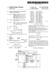
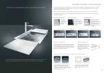
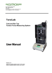
2013 Release 1.0 - 24/04/2013 USER MANUAL CONTENTS 1. OVERVIEW OF THE CAR ....................................................................... 4 2. CONTACTS ........................................................................................... 5 2.1. Organizers ....................................................................................... 5 2.2. Technical contacts ............................................................................ 5 2.3. Manufacturer.................................................................................... 5 2.4. Renault Sport extranet ...................................................................... 6 3. OVERALL DESCRIPTION ...................................................................... 7 3.1. Dimensions ...................................................................................... 7 3.2. Capacities ........................................................................................ 8 3.3. Technical Specifications ..................................................................... 8 4. USE...................................................................................................... 9 4.1. Switch panel .................................................................................... 9 4.2. Starting procedure .......................................................................... 10 4.3. Safety procedure ............................................................................ 10 4.5. Ballast location ............................................................................... 11 5. CHASSIS............................................................................................ 12 5.1. Basic Setup.................................................................................... 12 5.2. Setup adjustment ........................................................................... 13 5.3. Aero setup ..................................................................................... 13 5.4. Suspension geometry ...................................................................... 15 5.4.1. Toe/Camber shims position ........................................................ 15 5.4.2. Rear bracket position................................................................. 16 5.5. Damper setting .............................................................................. 17 5.6. Front antiroll stiffness setting ........................................................... 18 5.7. Brakes........................................................................................... 19 5.7.1. Discs / Pads bedding in procedure............................................... 19 5.7.2. Wear ....................................................................................... 19 5.8. Nosebox cap change ....................................................................... 19 5.9. Tightening torques.......................................................................... 20 6. ENGINE ............................................................................................. 21 7. TRANSMISSION / GEARBOX .............................................................. 22 7.1. Clutch bleeding procedure................................................................ 22 7.2. Ratio charts ................................................................................... 23 7.3. Lubrification ................................................................................... 23 7.4. Glue components............................................................................ 24 7.5. Gears ............................................................................................ 24 7.6. Selector......................................................................................... 26 7.7. Differential..................................................................................... 28 7.8. Final drive...................................................................................... 29 7.9. Bearings ........................................................................................ 31 7.10. Clutch shaft.................................................................................. 34 7.11. Rebuilding of the gearbox .............................................................. 35 7.12. Gear shift setup ............................................................................ 36 8. ELECTRONICS.................................................................................... 37 8.1. Dashboard ..................................................................................... 37 8.1.1. Driver pages ............................................................................ 37 2 Release 1.0 - 24/04/2013 8.1.2. Diag pages............................................................................... 38 8.1.3. Diag CAN ................................................................................. 39 8.1.4. Display settings ........................................................................ 40 8.1.5. Dash configuration .................................................................... 40 8.1.6. Synthesis operation................................................................... 43 8.2. Details of the transponder connector................................................. 44 8.3. Composition of the PI Data system kit ............................................... 44 The repair procedures prescribed by the manufacturer in this manual have been written in compliance with the technical specifications in force at publication issuing date. They are subject to modifications in case of changes made by the manufacturer to the production of the various components and accessories of his brand name vehicles". All copyrights are reserved to RENAULT SPORT TECHNOLOGIES. Reproducing or translating this document, even partially, and using the spare parts reference numbering system are prohibited without the previous written consent of SIGNATECH AUTOMOBILES © RENAULT SPORT TECHNOLOGIES 2013 3 Release 1.0 - 24/04/2013 1. OVERVIEW OF THE CAR 4 Release 1.0 - 24/04/2013 - 2. CONTACTS 2.1. Organizer Renault Sport Technologies ZA Courtaboeuf 2 14, Avenue des Tropiques 91978 Les Ulis Courtaboeuf Cedex FRANCE Tel : +33-1 76 82 40 00 Sporting coordinator: Rudy Thomann [email protected] 2.2. Technical contacts For any questions or advice, please contact: Renault Sport Technologies ZA Courtaboeuf 2 14, Avenue des Tropiques 91978 Les Ulis Courtaboeuf Cedex FRANCE Tel : +33-1 76 82 40 00 Fax : +33-1 76 82 12 40 http://extranet.renault-sport.com Racing Technical Support: Guillaume Argy Tel : +33-1 76 84 18 93 Mob: +33-6 84 93 86 46 [email protected] Racing Technical Dpt Referent: Julien Jehanne Tel : +33-1 76 82 41 25 [email protected] 2.3. Manufacturer Signatech Automobiles Parc Esprit 1 Rue Michael Faraday 18000 Bourges France Tel/Fax :+33-2 48 02 01 77 Racing Technical Support: Lionel Chevalier Tel : +33-2 48 02 01 77 [email protected] Spare Parts: Florent Pacholak Tel : +33-2 48 02 01 77 [email protected] 5 Release 1.0 - 24/04/2013 2.4. Renault Sport extranet The Renault Sport Extranet website is accessible for every FR1.6 owners, after asking for an access directly from the welcome page of the website: http://extranet-competition.renault-sport.com/ or All the technical documents issued are available through this website: - Technical Regulations User Manual Technical Bulletins & Information Notes Spare parts catalogue Softwares HQ Loom drawings and so on. 6 Release 1.0 - 24/04/2013 3. OVERALL DESCRIPTION 3.1. Dimensions Overall length 4118 mm Overall width 1670 mm Overall height 999 mm Wheelbase 2651 mm Front track 1486 mm Rear track 1436 mm Front overhang 935 mm Rear overhang 531 mm 7 Release 1.0 - 24/04/2013 3.2. Capacities Products Petrol Engine oil Gearbox oil Coolant Brake fluid Clutch fluid Quantity 43 L Around 6.5 L 2.1 L 6L 0.4 L 0.15 L Characteristics Unleaded 98 Elf HTX 825 (10W60) Elf HTX 735 (75W90) Elf HTX 115 Elf HTX 115 3.3. Technical Specifications Weight 470 kg without driver and fuel (with catalyser exhaust) Front suspension Push road, mono damper unit (non adjustable) Rear suspension Push road, twin damper unit (non adjustable) Wheels Rims : one piece Speedline aluminium alloy rim with central nut Rims size : Fr 8"x13" Rr 10"x13 Kumho tyres : Fr 180/53x13 Rr 220/54x13 Dunlop tyres : Fr 175/535x13 Rr 230/535x13 Brakes Engine 4 piston Alcon calipers, 274x18.5mm ventilated discs Right/Left foot adjustable pedal Renault Sport Type : K4M 854 – 1.6L Max power : 140 bhp @ 6800 rpm Max torque : 160 Nm @ 4500 rpm Max revs : 7200 rpm Transmission SADEV SL66 5 front gears + one reverse gear Shift cut system Free differential 8 Release 1.0 - 24/04/2013 4. USE 4.1. Switch panel 1 10 2 3 4 7 8 11 9 5 6 1- Unused Connector 2- Main switch 3- Rain light switch 4- Connector for the mechanic electronic throttle (joystick) 5- Dashboard reset 6- Neutral and reverse handgrip 7- Ignition switch 8- Starter button 9- Fuel pump switch for drain tank 10- Fire extinguisher handgrip 11- Brake balance handgrip (clock wise increases front brake pressure) “ON” is the up position of the switches 9 Release 1.0 - 24/04/2013 4.2. Starting procedure • • • • • • Switch the master switch and the ignition on. No throttle. Push the starter button few seconds. The engine must start. If the engine doesn’t start, switch ignition off and on and push the starter button again. After starting you can accelerate gently. Warm the engine up to 80°C before running. 4.3. Safety procedure Switch ignition and master switch off. For transportation it’s easy to disconnect the electrical system by unscrewing the main fuse (100A). In case of fire, the driver pulls the handgrip on the right side of the steering wheel or an external person pulls the red ring on the right side of the roll hoop. This action triggers the extinguisher and switches the electrical system off. After this action, the electrical system can be on again only by pushing the fire switch on the extinguisher ones (Spare parts catalog page 14 Ref 12). Fire extinguisher cables are located in two points: Behind the roll hoop Inside the cockpit 10 Release 1.0 - 24/04/2013 4.5. Ballast location The ballast must be placed inside the cockpit, under the driver seat. The lead ballast has to be fitted between the bottom of the chassis and the stainless steel cover. Ballast system are described as follows: • 3mm stainless steel cover : 2.0kg • 1.5 mm lead ballast: 1.5kg Maximum ballast weight possible: +/- 15kg. You can only fit the steel cover plate. Mounting screws: 3 FHC M5 with diam5x12 washers and nylstop nuts. Length depending of the thickness of the ballast Ballast mounting holes 11 Release 1.0 - 24/04/2013 5. CHASSIS 5.1. Basic Setup Gearbox SADEV SL66 Final drive 10/31 1st 11/35 2nd 14/31 3rd 18/30 5th 25/27 4th 19/25 Front Rear SPRINGS Spring Stiffness [lb/in - daN/mm] 800 Motion Ratio Wheel / Damper 14 0.86 DAMPERS 700 12.3 1.18 Nadal Tech non adjustable ANTIROLL Bellevilles Stack 11x1 Motion Ratio Wheel / Bellevilles 1.77 Element Stiffness [daN/mm] 81 GEOMETRY Ride Height [mm] 18 Castor [°] 10° Camber [°] -3.5° 33 -3.5° -2.5° -2.5° Toe per Wheel 1,5 mm OUT 1 mm IN Roll centre position vs ground [mm] 23 52 Anti-Dive 38% Anti-Squat 15% 40% WINGS Main [°] 4° Flap [°] 9° P2 = 3° TYRES Pressure [bar] @ 20° C 1.2 1.2 Hot Pressure [bar] 1.5-1.6 1.5-1.6 Kumho Circumference [mm] 1665 1696 12 Release 1.0 - 24/04/2013 5.2. Setup adjustment Adjustment Front Rear RIDE HEIGHT change 1 turn of damper platform (2mm) 1.7 mm 2.4 mm CAMBER change 1 mm shim 0.285° 0.278° 3.5mm shim 1° 0.97° +10mm ride height -0.3° +0.15° TOE change 1 turn (1mm) 0.653° around 4 mm at the Wheel 1.5 flat 1 mm at the wheel 0.157° around 1 mm at the wheel 1mm shim CASTER change 1mm shim 0.218° WING change 1mm shim -0.6° Special damper spanners are available (one for each size of platform) 5.3.available: Aero1setup Shim thickness mm, 1.5 mm and 2 mm. 15 mm 166 mm Ride Height Measurement Place 13 Release 1.0 - 24/04/2013 Front wing Wing angle measurement place 0° parallel to the car floor or to the reference plan on the top of the bellhousing Flap Angle adjustment – shims position The front wing shims must only be fitted on the rear of the front wing brackets. Available shims thickness: 0.5mm, 1mm and 2mm. Without shims, the wing angle is 5° (Maximum value) 14 Release 1.0 - 24/04/2013 Rear wing P3 = 6° P2 = 3° P1 = 0° P2 = 9° P1 = 0° 0° parallel to the car floor or to the reference plan on the top of the bellhousing 5.4. Suspension geometry 5.4.1. Toe/Camber shims position Front Camber Shims: 0.5-1-1.5-2mm 15 Release 1.0 - 24/04/2013 Rear Camber Shims: 0.5-1-1,5-2mm Rear Toe Shims: 0,5-1-1,5-2mm Rear toe and camber shims are the same. 5.4.2. Rear bracket position Only one rear bracket position is allowed (red fixing points) 16 Release 1.0 - 24/04/2013 5.5. Damper setting 73,9 60 40 20 Force (kgf) 0 -20 -40 -60 -80 -86,3 0,0 20 40 60 80 100 120 140 Velocity (mm/sec) 163,3 force [kg] Speed [mm/sec] bump min bump 20 14,35 100 160 bump max rebound min rebound rebound max 15,60 16,85 -13,16 -14,30 -15,44 44,34 48,20 52,06 -50,05 -54,40 -58,75 58,88 64,00 69,12 -71,02 -77,20 -83,38 gas force measured at middle stroke = 15kg +-1,5kg all measures are done at 30ºC shock temperature 17 Release 1.0 - 24/04/2013 5.6. Front antiroll stiffness setting The front antiroll stiffness is set by a Belleville washer stack. Belleville dimensions: diam 31.4 x 16.4mm thickness 1.75mm Only following Belleville stacks with the corresponding spacers are allowed: Stack Spacer Stiffness (daN/mm) Max Deflection (mm) 4x2 <<>><<>> 6x1 >>>>>> 444 2.4 5x2 <<>><<>><< 4x1 >>>> 355 3.0 6x2 <<>><<>><<>> 4x1 >>>> 296 3.6 7x2 <<>><<>><<>><< 254 4.2 8x2 <<>><<>><<>><<>> 9x2 <<>><<>><<>><<>><< 222 4.8 197 5.4 178 3.0 148 3.6 127 4.2 111 4.8 5x1 <><>< 6x1 <><><> 7x1 <><><>< 8x1 <><><><> 9x1 >>>>>>>>> 7x1 >>>>>>> 6x1 >>>>>> 5x1 >>>>> 9x1 <><><><>< 4x1 >>>> 99 5.4 10x1 <><><><><> 4x1 >>>> 89 6.0 11x1 <><><><><>< 81 6.6 12x1 <><><><><><> 74 7.2 13x1 <><><><><><>< 68 7.8 14x1 <><><><><><><> 63 8.4 15x1 <><><><><><><>< 59 9.0 16x1 <><><><><><><><> 56 9.6 Take care to respect the mounting direction of the Belleville stack with the smaller diameter of the Belleville in contact with the preload nut. If the Belleville stack needs a spacer, the spacer has to be mounted after the Belleville stack with the bigger diameter in contact with the preload nut. 18 Release 1.0 - 24/04/2013 5.7. Brakes 5.7.1. Discs / Pads bedding in procedure • • • • During the first 2 laps do not over heat the new brake discs and pads. Brake earlier than usually and with less brake pressure (50%) Don’t be aggressive, warm progressively the brakes by small and frequent braking: every 10 seconds. After 2 laps, do half slow lap to cool down the brakes Do again 2 laps like the first ones but with more brake pressure (75%) Do half lap to cool down the brakes and so after 5 laps you can brake like usualy. 5.7.2. Wear Disc nominal thickness: 18.5mm Disc minimal thickness: 16.5mm 5.8. Nosebox cap change In case of nosebox cap damage, it’s possible to change it. • Cut the nosebox cap at the mentioned dimensions. Around 20mm of the nose cap is still on the nosebox. • Unstick carefully this part of the nose cap. Take care not to damage the main part of the nosebox. • Use “ARALDITE 2031” to bond the new nose cap. For safety reason it’s forbidden to repair the nosebox if the honeycomb is damaged. 19 Release 1.0 - 24/04/2013 5.9. Tightening torques Bolt and nut Nm M5 10 M6 14 M8 25 M10 Roll Hoop 35 M10 40 M18 Wheel Nut 140 M20 Wheel Stud 180 Brake Bleeder 12 20 Release 1.0 - 24/04/2013 6. ENGINE • • • • • • • Optimum water temperature: 90°C Maximum water temperature: 105°C Maximum oil temperature: 140°C Revs limiter: 7200 rpm Engine oil and filter oil change : every 2500km Engine air filter cleaning: every 1000km Engine must be checked in case of an 8000RPM over rev 21 Release 1.0 - 24/04/2013 7. TRANSMISSION / GEARBOX The SADEV SL66-14 gearbox, is a sequential 5 front gears & one reverse gear with cut off system. Its weight is approximately 36 kg. It is equipped with a bevel gear differential. 7.1. Clutch bleeding procedure 22 Release 1.0 - 24/04/2013 7.2. Ratio charts Gear Ratio 1st 11x35 (0,314) 14x31 (0,451) 18x30 (0,6) 19x25 (0,76) 25x27 (0,925) nd 2 3rd 4th 5th Ref. D669002036J6J1 C66141830606J C66141925606J C66142527606J Reverse gear Primary shaft 11 Reverse gear 16 Secondary shaft 36 Final drive Secondary 10 shaft Crown 31 wheel 7.3. Lubrification Oil capacity: 2.1 L (at drain plug level) 1rst drain Drain frequency Viscosity After a 50Km running-in Each meeting 75W90 PARTICULAR PRECAUTIONS No additives should be added to the oil. The resulting consequences are not in any circumstances covered by the SADEV supplier. When topping up the gearbox oil, do not mix any other oil with that already in the box. Oil level plug 23 Release 1.0 - 24/04/2013 STORAGE AND USE Be particularly careful with any bottles which are open when used: Close the bottle again properly after use to prevent the introduction of water or dirt. Store bottles horizontally, protected from severe weather. Do not store bottles close to a washing station. Do not decant the oil into larger containers. WASHING UNDER PRESSURE When the gearbox is removed, seal all openings correctly to prevent the ingress of water into the gearbox. 7.4. Glue components Glue components and tightening torque are shown in the rebuild section. WARNING: Glue components have been chosen during tests sessions. Only ‘Loctite’ brand components must be used. Consequences of false glue component choice can’t be ensured by Sadev. 7.5. Gears FOUT90020081 Diff locking tool Removing - Engage neutral - Drain the gearbox through the lower plug (clean the oil level plug magnet) - Disconnect the potentiometer - Lock the differential using the dedicated 3 tool. - Remove the end cap (1) (4 M6 bolts) 4 Remove the secondary shaft nut (2) , its circlip and stopping washer Caution : It is left hand threaded. - Remove the back housing (3) (8 M7 nuts) 24 1 Release 1.0 - 24/04/2013 Caution : The secondary shaft, only guided with taper roller bearing and rested against the teeth, can drop a little. - Remove the fork axle (4). - Remove the gears 5th, 4th, 3rd, 2nd & 1st and reverse wheels, and all other parts of the primary and secondary stacks. - 6 Remove the reverse gear idler bolt (5). 8 7 Caution : It is glued, so use a hot air gun. - Remove the reverse gear idler - Remove the clutch shaft (7) (see 7.10) - Remove the primary shaft (6). Reinstallation - Clean and check the conditions of the parts. Clean the mating surfaces of the housings. - Reinstall the primary shaft (support the clutch shaft to slide the primary shaft) - Install the reverse gear idler (tighten the reverse gear idler bolt bonded with Loctite 648 to 5.5daN.m) - Reinstall all the parts in the reverse order as for removing. Lightly lubricate them with gearbox oil before fitting. - 9 Install the fork pin and make sure the fork actuating pins are in the relevant barrel slots. (Tool FOUT0085003 and check the barrel is in neutral position) Set up the primary simultaneously). - 5 2 & secondary stacks clearance (you can do this Primary stack adjusting shim (8): o If you did refit all the original parts, refit the original shim. o If not : install the finest shim of the set (F90020181), and close the gearbox (without glu or seal component & tighten the nuts moderatly). o Remove the differential (see 7.7), and check the primary stack axial clearance. 25 Release 1.0 - 24/04/2013 o - Choose the ideal adjusting shim (after setting, the primary line must be tight form 0 to 0.1mm) re-install the differential, re-open the gearbox and install it. Secondary stack preload adjusting shim (9): o In exclusion of wheels, wheels bearings, dogring & forks, if you did refit all the original parts, refit the original shim. o If not : install the thickest (2.5mm) shim of the set (F90020121), and close the gearbox (without glu or seal component & tighten the nuts moderatly). o Tighten the secondary shaft nut to 18daN.m (left hand thread) o Remove the differential (see 7.7), and check the secondary stack axial clearance “X”. o Calculate the shim thickness : 2.5mm – X. Choose the nearest thicker shim, re-install the differential remove the secondary shaft nut, reopen the gearbox and install it. - Coat the rear housing mating surface with Loctite 518, and install it. Thighten the M7 nuts to 2.2daN.m - Tighten the secondary shaft nut to 18daN.m (left hand thread), and install its stopping washer & the circlip. - Coat the end cap mating surface with Loctite 518, and install it. Thighten the M6 bolts bonded with Loctite 222 to 1.5daN.m - Reinstall and adjust the potentiometer. 7.6. Selector Removing the selector axle - Engage reverse gear - Drain the gearbox through the lower drain plug (Clean the drain plug magnet) - Remove the external axle (1) (2 M7 bolts). - Remove the reverse gear unlocking cable. - Remove the control closing block with the cut off switch (2) (2 M7 bolts). - Remove the dual pin rock pusher (3) (2 M5 bolts) - Introduce a round magnet FACOM (4) in the pusher guide hole and raise the dual pin rock making sure it is not in contact with the barrel. - Keeping the dual pin rock raised, make the selector axle turn ¼ of a turn and extract it from the control closing block side. 26 Release 1.0 - 24/04/2013 2 4 3 1 Reinstallation of the selector axle - Clean and check the conditions of the parts - Check the barrel is in reverse position. This position is visible when looking at the barrel through the selector axle hole : in reverse position, there is a notch on the barrel to let the selector axle go through. - Put the dual pin rock into the selector axle. - Insert the selector axle in the housing with the same position as when removing it. - Drive in the selector axle until the spring is completely compressed, turn it ¼ of a turn (in the opposite way to removing) and check the double ratchet is correctly installed in the barrel. - Install the dual pin rock pusher (3) (2 M5 bolts, Loctite 222, 0.5daN.m), control closing block with the cut off switch (2) (2 M7 bolts, Loctite 222, 2.2daN.m), Remove the external axle (1) (2 M7 bolts, Loctite 222, 2.2daN.m) and the reverse cable, being careful to clean and degrease all the screws. 1 Removal of barrel - Engage neutral - Drain the gearbox through the lower drain plug (Clean the drain plug magnet) - Remove the reverse gear unlocking cable & the potentiometer - Remove the indexor (1) - Lock the differential using the dedicated tool - Remove the end cap (4 M6 bolts) - Remove the secondary shaft nut, its circlip and stopping washer 4 3 Caution : It is left hand threaded. 2 27 Release 1.0 - 24/04/2013 - Remove the back housing (2) - Remove the fork pin (3) and disengage the forks to get out the fork actuating pins from the barrel slots - Remove the barrel (4) Reinstallation of the barrel - Clean and check the condition of the parts - Install the barrel taking care it’s resting well in its main housing bearing. - Adjust the barrel clearance: o If you refit all the original parts, refit the original shim. o If not : install the finest shim of the set (F90020041), and close the gearbox (without glu or seal component & tighten the nuts moderatly). o Remove the differential (see 7.7), and check the barrel axial clearance. o Choose the ideal adjusting shim (after setting, the clearance must be as near of 0mm as possible) re-install the differential & re-open the. - Install the chosen barrel clearance adjusting shim - Check the barrel is in neutral position. - Install the fork pin and make sure the fork actuating pins correctly fit the barrel slots. (Tool FOUT0085003) - Coat the rear housing mating surface with Loctite 518, and install it. Thighten the M7 nuts to 2.2daN.m - Tighten the secondary shaft nut to 18daN.m (left hand thread), and install its stopping washer & the circlip. - Coat the end cap mating surface with Loctite 518, and install it. Thighten the M6 bolts bonded with Loctite 222 to 1.5daN.m - Reinstall and adjust the potentiometer. 7.7. Differential Removing - Engage the neutral - Drain the gearbox through the lower drain plug (Clean the drain plug magnet) - Remove the differential housing (1) (11xM8 bolts) - Remove the differential (2) 28 2 1 Release 1.0 - 24/04/2013 Rebuild operation - Remove the bevel gears stops (3) (12xM6 bolts each) - Remove the bevel gears (4) noting their mounting side. - Remove the dowel pins (5) - Remove the planet gears, their axles and the nut. - 5 4 Clean an check the good conditions of the parts (change them if necessary). 3 - Reinstall the planet gears, their axles and the nut. - Reinstall new dowel pins. - Reinstall the bevel gear (taking care of their mounting side). - Reinstall the bevel gears stops. (for each one, tighten the 12xM6 bolts bonded with Loctite 243 to 1.5DaN.m) - Before re-installing, check the condition of the final drive (crownwheel and secondary shaft) and if necessary, change it (see 7.8) Reinstallation - Clean the threads , bolts & mating surfaces of the differential & main housings. - Install the differential. - Coat the differential/main housing mating surface with Loctite 518. - Install the differential housing (tighten the 11xM8bolts bonded with Loctite 222 to 2.2DaN.m) - Fill up the gearbox with oil to the Oil level. 7.8. Final drive Removal - Engage neutral Drain the gearbox through the lower plug (clean the oil level plug magnet) Disconnect the potentiometer Lock the differential using the dedicated tool. (FOUT90020081) Remove the end cap (4 M6 bolts) Remove the secondary shaft nut, its circlip and stopping washer Caution : It is left hand threaded. 29 Release 1.0 - 24/04/2013 - Remove the differential (see 7.7) Remove the gears (without primary shaft) (see 7.5) Remove the secondary shaft 2 Secondary shaft - - - Set the secondary shaft advance : Note the dimensions engraved inside the main housing (about 109.5mm) and on the secondary shaft (about 90mm) Make the following operation : housing dimension – shaft dimension – 18 = shim thickness Install the corresponding thickness shim (1), and the conical bearing on the shaft (2). Reinstall the secondary shaft and its gears (see 7.5). 4 Crownwheel - - - - 1 Remove the differential bearings (see 7.9) Remove the crownwheel. (8xM10 bolts) Clean and check the parts condition. Install the new crownwheel (tighten the M10 bolts bonded with Loctite 648 to 9DaN.m) Install the differential bearings (see 7.9) 3 Check the two differential bearings shim thicknesses, addition them and note the result (B). Set the final drive clearance : Install the FOUT90020401 (1) tool, and for each tooth of the tool, check the final drive clearance. The average clearance must be of 0.1 to 0.2mm. If the clearance is too high : make the crown wheel and pinion closer by increasing the spacer thickness at the ring gear side (2) and 30 1 Release 1.0 - 24/04/2013 decreasing the opposite spacer thickness (3) : you must keep the same total thickness If the clearance is too low : separate the crown wheel and pinion by decreasing the spacer thickness at the ring gear side and increasing the opposite spacer thickness : you must keep the same total thickness - - Process again until getting good values. Reinstall the gears (see 7.5) 3 2 7.9. Bearings Primary shaft bearings - Remove the primary shaft (see 7.5) - Remove the bearing (2) and spacer (3) on primary shaft using a press, taking care not to damage it - Clean and check the condition of bearing journal - Fit the new bearing using a press making sure it is correctly seated on its journal. - Fit the spacer making sure it is well positioned against the bearing inner race. 3 2 - Refit a new dowel pin - Remove the back housing lip seal - Heat the back casing using a hot air gun to approximately 120°C - Position an extractor FACOM (ref. U.49AD5) on the primary shaft bearing loosened in the back casing and extract it with a slide hammer 31 Release 1.0 - 24/04/2013 - Clean and check the conditions of the bearing journal - Put the new bearing using a press (or heating the shaft to approx. 120°C) making sure it is correctly seated in its housing - Install a new lip seal in the back housing. - Install the primary shaft and set up the primary line shims (see 7.5) Barrel bearings - Remove the barrel (see 7.6) - Remove the barrel bearing (4) using a press and taking care not to damage it - Clean and check the condition of the bearing journal - Install the new bearing using a press and making sure it is well positioned against the shoulder - Remove the back casing lip seal - Heat the back casing using a hot air gun to approximately 120°C - Position an extractor FACOM (ref. U.49AD5) on the primary shaft bearing loosened in the back casing and extract it with a slide hammer - Clean and check the conditions of the bearing journal - Put the new bearing using a press making sure it is correctly seated in its housing - Install the lip seal in the back housing after checking its condition - Reinstall the barrel (see 7.6) Secondary shaft bearings and 4 - Remove the differential secondary shaft (see 7.8) the - Remove the front plate (1) (11xM6 bolts) - Remove the back casing lip seal - Heat the back casing using a hot air gun to approximately 120°C - Extract the external ring from the back casing by hitting the ring through the oil way hole - Clean and check the condition of the bearing journal - Fit the new ring using a press and 32 1 Release 1.0 - 24/04/2013 making sure is correctly seated in its housing - Install the lip seal in the back housing after checking its condition - Extract the external ring from the main casing hitting the ring by the 3 dedicated holes (2) - Clean and check the condition of the bearing journal - Put the new ring using a press and making sure is correctly seated in its housing - Remove the secondary shaft bearing using possibly the tool FACOM (ref. U.53T1) taking care not to damage the bearing journal - Clean and check the condition of the bearing journal - Install the new bearing using a press and making sure it is well positioned against the spacer adjuster - Reinstall the differential and the gears (see 7.5) - Reinstall the front plate. (tighten the 11xM6 bolts bonded with LOCTITE 222 to 0.5DaN.m) 2 1 Differential bearings - Remove the differential (see 7.7) - Remove the differential case bearings (1) using a press and taking care not to damage it - Clean and condition. - check the parts 2 Fit the new bearings using a press making sure it is correctly seated on its journal. 33 1 2 Release 1.0 - 24/04/2013 - Set the bearings preload (only if you changed the main housing, the differential housing, the differential case or the bearings): Caution : You will have to set the final drive clearance too (see §6-4-3). - Install the differential and the thinnest shims (2) (1.5mm) between each bearing and its housing. - Install the differential housing, tightening the bolts moderately. - Measure the axial clearance of the differential “A”. Note : It is tight mounted, so you will have to push hard from one side and then from the other of de differential case to check the clearance. - Make the following operation : A+3mm+0.1mm=B Caution : Note it, this is an important measure for the final drive clearance set up. - Remove the differential. - Reinstall the differential (see 7.7). On each side, use shim thicknesses equal to B/2. 7.10. Clutch shaft Removal - Drain the gearbox through the lower drain plug (Clean the drain plug magnet) - Remove the lip seal from the front side of the gearbox - Remove the circlip which retains the clutch shaft bearing - Remove the clutch shaft 1 2 Reinstalling - Clean and check the conditions of the parts - Reinstall the clutch shaft inserting it in the primary shaft (mesh a speed and lock the differential if necessary) - Reinstall a circlip to lock the clutch shaft bearing - Reinstall a new lip seal 34 Release 1.0 - 24/04/2013 7.11. Rebuilding of the gearbox In Sadev workshop rebuilding Notes : - The gearboxes are delivered leaded and numbered. - The absence of lead 'Sadev' imposes a careful attitude in the event of minor or major problem to us, and applies to complete reserve of our share if necessary. Return gear boxes to revision : At the time of the return of the gearboxes in our buildings, a certain procedure of delivery has to be respected, so that our intervention can be total, and practical (casing ' closed' for passage to the bench). We must receive the complete product as described below: - Release bearing in place - entry and exit of lubrication closed by plugs envisaged for this purpose (Goodridge, SpeedFlow…) - Gear box drained and cleaned - Drain plug and drain plug seal in place - Differential in place - A card specifying the kilometers of the special stage and connection since the last service, available near our sales department The absence of elements can be specified on the card, but in case of doubt, the material will be send back re-equipped. Administrative procedure: 1. 2. 3. 4. Send a request for service to SADEV sales department Forward The material and its card (description above) in our workshops Approve the estimate presented by SADEV sales department APPROXIMATELY 2 TO 3 WEEKS OF DELIVERY TIME MUST BE CONSIDERED Personal revision: After sale parts for customers who want to proceed a revision by themselves, are delivered only by SADEV sales service. SADEV IS NOT RESPONSIBLE FOR ANY DAMAGE FOLLOWING A REVISION NOT EXECUTED IN A SADEV AGREED TECHNICAL SERVICE (LIST ON DEMAND). As every mechanical part which is dedicated for racing, there is not warranty at all from our side. 35 Release 1.0 - 24/04/2013 7.12. Gear shift setup - - - Pull the gear shift level to upshift. No need to use clutch and to throttle off. The ignition cut is automatic and has to be set-up. There is a switch cut on the left side of the gear box at the end of the barrel drive axle. It’s screwed with shims to adjust its position. Each car is delivered with a set of shims. When reducing the thickness of the shims, the ignition cut is earlier in the level movement. As soon as the barrel drive axle starts moving (first mm), the ignition has to be cut off. It’s possible to check the cut off position without running engine. Switch ignition on. The EDiag LED on the right of the dashboard is flashing. When pushing the barrel drive axle, the LED turns on permanently. 36 Release 1.0 - 24/04/2013 8. ELECTRONICS 8.1. Dashboard Alarm Revs - Direction Shift light Revs - Direction Page change and escape Validatio n Mechanic alarm Diag/EC U Decrement (-) Increment (+) 8.1.1. Driver pages Three driver pages are available. You can change the driver pages by pushing the red button. pulse on the red button pulse on the red button pulse on the red button 37 Release 1.0 - 24/04/2013 8.1.2. Diag pages To access to the different Diag pages : - Hold the green button down until this page appears : - Move the cursor with the blue or yellow button to access the 4 different Diag (Lap time ; Mini/Maxi ; Alarm ; Custom). When the cursor is located on the Diag you want, press the green button to display the page, and scroll it. Push the red button to exit. One of the three driver pages -The color of the arrows corresponds to the color of the BP -Simple arrow = short pulse -Double arrow = long pulse Diag menu Laptime Laptime displaying screen Min/max Min/Max displaying screen Alarm Custom Time alarm displaying screen Mechanic page 1 Mechani c page 2 Details on the 4 Diag pages: • Lap time: displays the lap times made. Sec: indicates the session by a letter. Lap: indicates which lap of the session. Time: indicates the lap time. Date of the lap Start time of the lap 38 Release 1.0 - 24/04/2013 With the blue or yellow button, you can select a lap time. The date and beginning hour of this lap are displayed in the two little windows located on the right. • Mini-Maxi: mini and maxi values of each parameter are displayed. To display all the parameters, scroll with the blue or yellow button. You can reset the values by pressing the blue and yellow buttons simultaneously until crosses (x) appear. • Alarm: displays how long, in seconds, the parameter has remained in "alarm" . To display another parameter, scroll by pushing the blue or yellow buttons. To reset the alarms completely, just press the blue and yellow buttons simultaneously, until the length figures are back to zero (all the duration of the different parameters will be reset at the same time). • Custom: these pages allow to display other parameters in "real time". Push the green button to scroll down. Mechanic page 1 Mechanic page 2 8.1.3. Diag CAN You can access to the diag can page by pushing simultaneously the blue and yellow button when the dash is displaying the first mechanic page. 39 Release 1.0 - 24/04/2013 8.1.4. Display settings To reach the display settings, press together the red and green buttons and hold them down until the page appears. To move within the different parameters, you have to use the green button. To change the value, you need to press the blue button in order to set the value down, and the yellow one to rise it up. Values go from 1 to 10. • • • • Contrast: to setup the shade between the screen background and the written indications. Backlight: to modify the brightness of the screen background. Led: to set up the brightness of the LEDs. Day and night: Set up for night or daylight. 8.1.5. Dash configuration To reach the configuration menu, push the green button before to raise the ignition switch. Once the page is displayed, move the cursor with the blue or yellow buttons. When the cursor is on the parameter to tune, use the green button to validate and the red one to exit. Push the green button before to raise the ignition switch Driver pages Configuration menu Beacon -The color of the arrows corresponds to the color of the BP -Simple arrow = short pulse -Double arrow = long pulse Beacon config. screen Alarm Alarm config. screen Gear Gear config. screen Led Led config. screen Rpm+Speed Rpm + Speed config. screen About… About… screen 40 Release 1.0 - 24/04/2013 Details on the configuration pages: • Beacon: to set up the timing parameters. Press the green button to select one of the three parameters and the blue or yellow one to adjust the time in seconds. Min lap time: to set the minimum gap time between two laps (to avoid in between beacons on the track). Display delay: to set the delay in seconds, between the time the beacon is set off and the lap time displayed on the screen. Display time: to set the length of time, during which the lap time remains displayed. • Alarms: to set the min and the max values of warning of the different parameters. You go from one value to the other by pushing the green button and you adjust the value thanks to the blue and yellow buttons (the unit value is displayed next to the given parameter). • Gear: to set the minimum and maximum of each gear (in volt) In the little window on the right, you have the voltage value given by the barrel potentiometer for the current gear engaged (R; N; 1). Setting example : for the first gear - Put the first gear - Check the value displays in the box current input - Move the cursor with the green button on the first row - Adjust the min and max values to “frame” the current input value with the blue or yellow button. NB: keep a little margin between the max value of a gear and the min value the following gear. 41 Release 1.0 - 24/04/2013 • Led: to set the revs leds and the shift led switch on (on top of the dash). You switch from a value to the other by pushing the green button and you tune the value with the blue and yellow buttons. • Bargraph first led: to set the first bargraph led (green) switch on. Bargraph last led: to set the last bargraph led (orange) switch on. Led shift: to set the revs (rpm) for which the shift led lights. RPM+Speed: Allow to adjust the number of top per rotation on engine target for the calculation of the engine revs, and the number of top per rotation on the wheel target and the circumference of the wheel (in mm) for the calculation of the vehicle speed. You switch from one value to the other by pushing the green button, and you adjust the value with the blue and yellow buttons. • About: This window contains information about the Firmware used in this Dash, the date of the firmware and the appliance specific configuration. 42 Release 1.0 - 24/04/2013 8.1.6. Synthesis operation To access the config. menu : Push the green button before to raise the ignition switch Home Screen Delay 3s Configuration menu Beacon Beacon config screen Alarm Alarm config screen Gear Gear config screen Led config screen Led Driver Page 1 Rpm +Speed Rpm + Speed config screen About… About… screen Driver Page 2 Driver Page 3 Diag menu Laptime Laptime displaying screen Min/max Mini maxi displaying screen Alarm Custom Time alarm displaying screen Mechanic page 1 Can Diag 43 Mechanic page 2 Release 1.0 - 24/04/2013 8.2. Details of the transponder connector DTM04-2P connector Pin1: +12V Pin2: Ground 8.3. Composition of the PI Data system kit • • • • • • • One PI compact logger Signatech spec with an integrated lateral accelerometer One compact flash card o Note: This card must not exceed 2GB memory One steering angle sensor with its fastening Two wheel speed sensors Two brake pressure sensors with its hoses, bleeders and support One beacon receiver The PI Toolbox and Pectel Card Management sofwares 44