1
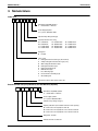
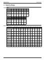
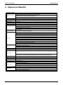
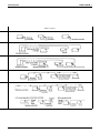
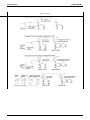
EDUS 391004 - M_a General Information RXYQ-PB REYQ-P(B) AMERICAS EDUS391004-M_a General Information ..........................................................................EDUS391004-M_a (This booklet) Indoor Units Ceiling-Mounted Cassette Type (Round Flow) .......... FXFQ-P ............EDUS391000-F1 4-Way Ceiling Mounted Cassette Type (2’×2’) .......... FXZQ-M .............EDUS39-800-F9 Slim Ceiling Mounted Duct Type ......................... FXDQ-M .............EDUS39-600-F2 Ceiling Mounted Duct Type................................ FXMQ-P .......... EDUS39-900A-F4 Ceiling Mounted Duct Type................................ FXMQ-M ........ EDUS39-900A-F11 Ceiling Suspended Type ................................... FXHQ-M .............EDUS39-600-F5 Wall Mounted Type .......................................... FXAQ-M .............EDUS39-600-F6 Floor Standing Type / Concealed Floor Standing Type .............. FXLQ-M,FXNQ-M .............EDUS39-600-F7 Air Handling Unit ............................................. FXTQ-PA ..........EDUS391000-F12 Branch Selector Units ....................................... BSVQ-P .............EDUS39-900-F8 FXMQ-MF ........ EDUS39-900A-F10 RXYQ-PB 460V ..... EDUS391005-R1 Outdoor Air Processing Unit Outdoor Air Processing Unit............................... Outdoor Units Heat Pump ..................................................... 230V ..... EDUS391006-R1 Heat Recovery ................................................ REYQ-PB 460V ..... EDUS391005-R2 230V ..... EDUS391006-R2 Installation of Outdoor Units................................................................ EDUS391004-N Controls .................................................................................................EDUS391000-C Remote Controller BRC1E71.......................................................................................... EDUS72-975 Table of Contents i Introduction EDUS391004-M_a 1. Introduction Preface Due to higher quality, more sophisticated building environments, there is now a greater demand for multiple-unit, flexible air-conditioning systems that serve individual needs. Energy efficiency and low maintenance are also in high demand considering heightened social awareness of the significance of energy consumption and environmentally safe operation. Daikin is the sole air conditioning company in the world that manufactures every component from refrigerant to complete air conditioning systems. Our commitment to offering the best for both people and the environment, inspires us to develop new systems that make the most effective use of energy resources and protect the ozone layer. Daikin is the first in the industry to develop the VRV system, and offers enhanced R-410A with the innovative Inverter VRV system. This publication contains a variety of information related to the design and installation of this new VRV System. We hope this information deepens your understanding of the system and helps you to efficiently develop its highly evolved characteristics. Global Operations Division ii Introduction EDUS391004-M_a General Information 1. Model Names of Indoor/Outdoor Units ...................................2 2. External Appearance ..............................................................5 2.1 2.2 2.3 2.4 Indoor Units ............................................................................. 5 Air Treatment EquipmentOutdoor-Air Processing Unit ............ 5 Outdoor Units (RXYQ) ............................................................. 6 Outdoor Units (REYQ) ............................................................. 6 3. Nomenclature..........................................................................7 4. Capacity Range ......................................................................9 5. Features and Benefits...........................................................10 5.1 System Capacity Range ........................................................ 11 5.2 Efficiency Improvements........................................................ 12 5.3 Piping Capabilities ................................................................. 13 5.4 Connection Index................................................................... 14 5.5 Condenser External Static Pressure...................................... 15 5.6 Improved Branch Selector Box .............................................. 15 5.7 Limitation of Capacity Index for Heat Recovery .................... 16 5.8 Industry Leading Advanced Defrost Cycle............................. 17 5.9 Low Ambient Cooling Enhancement...................................... 17 5.10 Built-In System Redundancy ............................................... 18 6. Control Systems....................................................................19 7. DAIKIN Building Air Conditioning Control System (D-BACS).......................................................................................22 7.1 System Configuration (Central Remote Controller) ............... 22 8. Control System .....................................................................23 8.1 8.2 8.3 8.4 8.5 8.6 Various Control by Liquid Crystal Remote Controller ............ 23 Building Control System Introduction..................................... 28 Specifications of the Control Wiring....................................... 34 Wiring Example...................................................................... 34 Length of Transmission Wiring .............................................. 36 Connection Method................................................................ 37 9. Guide Specifications .............................................................45 9.1 Guide Specifications .............................................................. 45 10. CAUTION FOR REFRIGERANT LEAKS ...........................47 11. Safety Devices Setting........................................................48 Table of Contents 1 Model Names of Indoor/Outdoor Units EDUS391004-M_a 1. Model Names of Indoor/Outdoor Units Indoor Units Type Power Supply, Compatibility Symbol Model Name Ceiling Mounted Cassette Type (Round Flow) FXFQ 4 Way Ceiling Mounted Cassette Type (2’×2’) FXZQ 07M7 09M7 12M7 18M7 Slim Ceiling Mounted Duct Type FXDQ 07M 09M 12M Ceiling Mounted Duct Type Ceiling Mounted Duct Type Ceiling Suspended Type FXMQ 07P 09P FXMQ — FXHQ Wall Mounted Type — 09P 12P 18P 24P 30P 36P — 48P — — — — — — — — — — — 18M 24M — — — — — — — 12P 18P 24P 30P 36P — 48P — — — — — — — — — — — — 72M 96M — — 12M — 24M — 36M — — — — — FXAQ 07M 09M 12M 18M 24M — — — — — — — Floor Standing Type FXLQ — — 12M 18M 24M — — — — — — — Concealed Floor Standing Type FXNQ — — 12M 18M 24M — — — — — — — Air Handling Unit FXTQ — — 12PA 18PA 24PA 30PA 36PA 42PA 48PA 54PA — — VJU Branch Selector Units Type Heat Recovery Series Power Supply, Compatibility Symbol Model Name BSVQ 36P 60P 96P VJU Outdoor-Air Processing Unit Series Power Supply, Compatibility Symbol Model Name FXMQ 48MF 72MF 96MF VJU Outdoor Units (Inverter Series) Model Name Type Heat Pump Heat Recovery 6 ton Heat Recovery 12 ton 14 ton 16 ton 18 ton Power Supply, Compatibility Symbol RXYQ- 72PT 96PT 120PT 144PB 168PB 192PB 216PB TJ 460V RXYQ- 72PY 96PY 120PY 144PB 168PB 192PB 216PB YD 230V REYQ- 72PT 96PT 120PT 144PB 168PB 192PB 216PB TJ 460V REYQ- 72PY 96PY 120PY 144PB 168PB 192PB 216PB YD 20 ton 22 ton 24 ton 26 ton 28 ton 30 ton Model Name Power Supply, Compatibility Symbol 230V RXYQ- 240PB 264PB 288PB 312PB 336PB 360PB TJ 460V RXYQ- 240PB 264PB 288PB 312PB 336PB 360PB YD 230V REYQ- 240PB 264PB 288PB 312PB 336PB — TJ 460V REYQ- 240PB 264PB 288PB 312PB 336PB — YD VJ: YD: TJ: U(VJU): 2 10 ton 230V Type Heat Pump 8 ton 1 phase, 208/230V, 60Hz 3 phase, 460V, 60Hz 3 phase, 208/230V, 60Hz Standard Compatibility Symbol General Information EDUS391004-M_a Model Names of Indoor/Outdoor Units Combination of Outdoor Units Heat Pump 460V Model Name RXYQ72PBYD RXYQ96PBYD RXYQ120PBYD RXYQ144PBYD RXYQ168PBYD Outdoor Unit 1 RXYQ72PBYD RXYQ96PBYD RXYQ120PBYD RXYQ72PBYD RXYQ72PBYD Outdoor Unit 2 — — — RXYQ72PBYD RXYQ96PBYD Outdoor Unit 3 — — — — — Model Name RXYQ192PBYD RXYQ216PBYD RXYQ240PBYD RXYQ264PBYD RXYQ288PBYD Outdoor Unit 1 RXYQ72PBYD RXYQ96PBYD RXYQ120PBYD RXYQ72PBYD RXYQ72PBYD Outdoor Unit 2 RXYQ120PBYD RXYQ120PBYD RXYQ120PBYD RXYQ96PBYD RXYQ96PBYD Outdoor Unit 3 — — — RXYQ96PBYD RXYQ120PBYD Model Name RXYQ312PBYD RXYQ336PBYD RXYQ360PBYD Outdoor Unit 1 RXYQ72PBYD RXYQ96PBYD RXYQ120PBYD Outdoor Unit 2 RXYQ120PBYD RXYQ120PBYD RXYQ120PBYD Outdoor Unit 3 RXYQ120PBYD RXYQ120PBYD RXYQ120PBYD Heat Pump 230V Model Name RXYQ72PBTJ RXYQ96PBTJ RXYQ120PBTJ RXYQ144PBTJ RXYQ168PBTJ Outdoor Unit 1 RXYQ72PBTJ RXYQ96PBTJ RXYQ120PBTJ RXYQ144PBTJ RXYQ72PBTJ Outdoor Unit 2 — — — — RXYQ96PBTJ Outdoor Unit 3 — — — — — Model Name RXYQ192PBTJ RXYQ216PBTJ RXYQ240PBTJ RXYQ264PBTJ RXYQ288PBTJ Outdoor Unit 1 RXYQ72PBTJ RXYQ96PBTJ RXYQ120PBTJ RXYQ72PBTJ RXYQ72PBTJ Outdoor Unit 2 RXYQ120PBTJ RXYQ120PBTJ RXYQ120PBTJ RXYQ96PBTJ RXYQ96PBTJ Outdoor Unit 3 — — — RXYQ96PBTJ RXYQ120PBTJ Model Name RXYQ312PBTJ RXYQ336PBTJ RXYQ360PBTJ Outdoor Unit 1 RXYQ72PBTJ RXYQ96PBTJ RXYQ120PBTJ Outdoor Unit 2 RXYQ120PBTJ RXYQ120PBTJ RXYQ120PBTJ Outdoor Unit 3 RXYQ120PBTJ RXYQ120PBTJ RXYQ120PBTJ Heat Recovery 460V Model Name REYQ72PYDN REYQ96PYDN REYQ120PYDN REYQ144PBYD REYQ168PBYD Outdoor Unit 1 REYQ72PYDN REYQ96PYDN REYQ120PYDN REMQ72PBYD REMQ72PBYD Outdoor Unit 2 — — — REMQ72PBYD REMQ96PBYD Outdoor Unit 3 — — — — — Model Name REYQ192PBYD REYQ216PBYD REYQ240PBYD REYQ264PBYD REYQ288PBYD Outdoor Unit 1 REMQ96PBYD REMQ96PBYD REMQ120PBYD REMQ72PBYD REMQ72PBYD Outdoor Unit 2 REMQ96PBYD REMQ120PBYD REMQ120PBYD REMQ96PBYD REMQ96PBYD Outdoor Unit 3 — — — REMQ96PBYD REMQ120PBYD REYQ336PBYD Model Name REYQ312PBYD Outdoor Unit 1 REMQ96PBYD REMQ96PBYD Outdoor Unit 2 REMQ96PBYD REMQ120PBYD Outdoor Unit 3 REMQ120PBYD REMQ120PBYD General Information 3 Model Names of Indoor/Outdoor Units EDUS391004-M_a Heat Recovery 230V Model Name REYQ72PTJU REYQ96PTJU REYQ120PTJU REYQ144PBTJ REYQ168PBTJ Outdoor Unit 1 REYQ72PTJU REYQ96PTJU REYQ120PTJU REYQ144PBTJ REMQ72PBTJ Outdoor Unit 2 — — — — REMQ96PBTJ Outdoor Unit 3 — — — — — Model Name REYQ192PBTJ REYQ216PBTJ REYQ240PBTJ REYQ264PBTJ REYQ288PBTJ Outdoor Unit 1 REMQ96PBTJ REMQ96PBTJ REMQ120PBTJ REMQ72PBTJ REMQ72PBTJ Outdoor Unit 2 REMQ96PBTJ REMQ120PBTJ REMQ120PBTJ REMQ96PBTJ REMQ96PBTJ Outdoor Unit 3 — — — REMQ96PBTJ REMQ120PBTJ REYQ336PBTJ Model Name REYQ312PBTJ Outdoor Unit 1 REMQ96PBTJ REMQ96PBTJ Outdoor Unit 2 REMQ96PBTJ REMQ120PBTJ Outdoor Unit 3 REMQ120PBTJ REMQ120PBTJ 4 General Information EDUS391004-M_a External Appearance 2. External Appearance 2.1 Indoor Units Ceiling mounted cassette type (Round flow) FXFQ09PVJU FXFQ12PVJU FXFQ18PVJU FXFQ24PVJU FXFQ30PVJU FXFQ36PVJU FXFQ48PVJU 4 way ceiling mounted cassette type (2’×2’) FXZQ07M7VJU FXZQ09M7VJU FXZQ12M7VJU FXZQ18M7VJU Slim ceiling-mounted duct type FXDQ07MVJU FXDQ09MVJU FXDQ12MVJU FXDQ18MVJU FXDQ24MVJU Ceiling-mounted duct type FXMQ07PVJU FXMQ09PVJU FXMQ12PVJU FXMQ18PVJU FXMQ24PVJU FXMQ30PVJU FXMQ36PVJU FXMQ48PVJU Ceiling-mounted duct type FXMQ72MVJU FXMQ96MVJU Wall mounted type FXAQ07MVJU FXAQ09MVJU FXAQ12MVJU FXAQ18MVJU FXAQ24MVJU Floor standing type FXLQ12MVJU FXLQ18MVJU FXLQ24MVJU Concealed-floor standing type FXNQ12MVJU FXNQ18MVJU FXNQ24MVJU Air handling unit FXTQ12PAVJU FXTQ18PAVJU FXTQ24PAVJU FXTQ30PAVJU FXTQ36PAVJU FXTQ42PAVJU FXTQ48PAVJU FXTQ54PAVJU Branch Selector Units BSVQ36PVJU BSVQ60PVJU BSVQ96PVJU Ceiling suspended type FXHQ12MVJU FXHQ24MVJU FXHQ36MVJU 2.2 Outdoor-Air Processing Unit Outdoor-air processing unit FXMQ48MFVJU FXMQ72MFVJU FXMQ96MFVJU General Information 5 External Appearance 2.3 2.4 6 EDUS391004-M_a Outdoor Units (RXYQ) RXYQ72PBYD RXYQ72PBTJ RXYQ96/120PBYD RXYQ96/120PBTJ 6 ton 8, 10 ton RXYQ144PBTJ 12 ton RXYQ168/192PBYD RXYQ168/192PBTJ RXYQ216/240PBYD RXYQ216/240PBTJ 14, 16 ton 18, 20 ton RXYQ264/288/312PBYD RXYQ264/288/312PBTJ RXYQ336/360PBYD RXYQ336/360PBTJ 22, 24, 26 ton 28, 30 ton Outdoor Units (REYQ) REYQ72/96/120PYDN REYQ72/96/120PTJU,144PBTJ REYQ144/168/192/216/240PBYD REYQ168/192/216/240PBTJ REYQ264/288/312/336PBYD REYQ264/288/312/336PBTJ 6, 8, 10, 12 ton 12, 14, 16, 18, 20 ton 22, 24, 26, 28 ton General Information EDUS391004-M_a Nomenclature 3. Nomenclature Indoor Unit FX M Q 48 P VJ U Standard Compatibility Symbol U : United States of America Power Supply Symbol VJ : 1 phase, 208/230V, 60Hz Indicates Major Design Category Capacity Indication in Cooling 07 : 7,500 Btu/h 24 : 24,000 09 : 9,500 Btu/h 30 : 30,000 12 : 12,000 Btu/h 36 : 36,000 18 : 18,000 Btu/h 42 : 42,000 Btu/h Btu/h Btu/h Btu/h 48 : 48,000 54 : 54,000 72 : 72,000 96 : 96,000 Btu/h Btu/h Btu/h Btu/h Refrigerant Q : R-410A Type of Unit F : Ceiling Mounted Cassette Type (Round Flow) Z : 4 Way Ceiling Mounted Cassette Type (2'×2') D : Slim Ceiling Mounted Duct Type M : Ceiling Mounted Duct Type H : Ceiling Suspended Type A : Wall Mounted Type L : Floor Standing Type N : Concealed Floor Standing Type T : Air Handling Unit Indicates that this is VRV system indoor unit. Branch Selector Unit (Only Necessary for Heat Recovery System) BSV Q 36 P VJ U Standard Compatibility Symbol U : United States of America Power supply symbol VJ : 1 phase, 208/230V, 60Hz Indicates major design category Capacity Indication (Connectable total indoor unit capacity) 36 : Total indoor unit capacity less than 36 60 : Total indoor unit capacity 36 or more but less than 60 96 : Total indoor unit capacity 60 or more but less than 96 Refrigerant : R-410A Indicates that this is a BS unit. General Information 7 Nomenclature EDUS391004-M_a Outdoor Unit RXY Q 96 PB TJ Power supply symbol YD : 3 phase, 460V, 60Hz TJ : 3 phase, 208/230V, 60Hz Indicates major design category Capacity Indication in cooling 72 : 72,000 Btu/h 192 : 192,000 Btu/h 96 : 96,000 Btu/h 216 : 216,000 Btu/h 120 : 120,000 Btu/h 240 : 240,000 Btu/h 144 : 144,000 Btu/h 264 : 264,000 Btu/h 168 : 168,000 Btu/h 288 : 288,000 Btu/h 312 : 312,000 Btu/h 336 : 336,000 Btu/h 360 : 360,000 Btu/h Refrigerant type Q : R-410A Indicates that this is a RXY : Heat Pump Type REY : Heat Recovery Type REM : Heat Recovery Multi Unit 8 General Information EDUS391004-M_a Capacity Range 4. Capacity Range Outdoor Units Capacity Range 6 ton 8 ton 10 ton 12 ton 14 ton 16 ton RXYQ 72PB 96PB 120PB 144PB 168PB 192PB 216PB REYQ 72P 96P 120P 144PB 168PB 192PB 216PB Max. Number of Connectable Indoor Units 12 16 20 25 29 33 37 Total Capacity Index of Indoor Units to be Connected 36 ~ 93 48 ~ 124 60 ~ 156 72 ~ 187 84 ~ 218 96 ~ 249 108 ~ 280 Capacity Range 20 ton 22 ton 24 ton 26 ton 28 ton 30 ton RXYQ 240PB 264PB 288PB 312PB 336PB 360PB REYQ 240PB 264PB 288PB 312PB 336PB — Max. Number of Connectable Indoor Units 41 45 49 54 58 62 Total Capacity Index of Indoor Units to be Connected 120 ~ 312 132 ~ 343 144 ~ 374 156 ~ 405 168 ~ 436 180 ~ 468 18 ton Indoor Units Capacity Range 0.6ton 0.8ton 1ton 1.5ton 2ton 2.5ton 3ton 3.5ton 4ton 4.5ton 6ton 8ton Capacity Index 7.5 9.5 12 18 24 30 36 42 48 54 72 96 Ceiling Mounted Cassette Type (Round Flow) FXFQ — 09P 12P 18P 24P 30P 36P — 48P — — — Ceiling Mounted Cassette Type (2’×2’) FXZQ 07M7 09M7 12M7 18M7 — — — — — — — — Slim ceiling Mounted Duct Type FXDQ 07M 09M 12M 18M 24M — — — — — — — Ceiling Mounted Duct Type FXMQ 07P 09P 12P 18P 24P 30P 36P — 48P — — — Ceiling Mounted Duct Type FXMQ — — — — — — — — — — 72M 96M Ceiling Suspended Type FXHQ — — 12M — 24M — 36M — — — — — Wall Mounted Type FXAQ 07M 09M 12M 18M 24M — — — — — — — Floor Standing Type FXLQ — — 12M 18M 24M — — — — — — — Connected Floor Standing Type FXNQ — — 12M 18M 24M — — — — — — — Air Handling Unit FXTQ — — 12PA 18PA 24PA 30PA 36PA 42PA 48PA 54PA — — General Information 9 Features and Benefits EDUS391004-M_a 5. Features and Benefits 959,,,)HDWXUHV%HQHILWV 93KDVH7RQ6LQJOH&DELQHWDQG7RQ'RXEOH0RGXOH&DELQHWDQG7RQ 7ULSOH0RGXOH&DELQHQW&RQGHQVLQJ8QLWVDYDLODEOHIRU&RPPHUFLDO$SSOLFDWLRQV 9ROWDJH3ODWIRUP2SHUDWLRQ &KRLFH 93KDVHDQG7RQ6LQJOH&DELQHWDQG7RQ'RXEOH0RGXOH&DELQHWDQG7RQ7ULSOH0RGXOH &DELQHW&RQGHQVLQJ8QLWVDYDLODEOHIRU/LJKW&RPPHUFLDO$SSOLFDWLRQV +HDW3XPSDQG+HDW5HFRYHU\6\VWHPVSURYLGLQJ6LPXOWDQHRXV+HDWLQJDQG&RROLQJDUHDYDLODEOHZLWKERWKYROWDJHSODWIRUPV $GYDQFHG=RQLQJ ,QGLYLGXDO=RQHVFDQEHSURYLGHGIRUXSWR]RQHVRQD6LQJOH959,,,V\VWHP ,QGHSHQGHQW&RQWURO (DFK)DQ&RLO8QLWXVHVDGHGLFDWHG(OHFWURQLF([SDQVLRQ9DOYHIRUVXSHULRUURRPWHPSHUDWXUHFRQWUROPHDQLQJLQGLYLGXDOFRQWUROLQDOO QHFHVVDU\]RQHV $EVROXWH5HOLDELOLW\ 7KHODWHVW*7\SH'DLNLQGHVLJQHGPDQXIDFWXUHG,QYHUWHU6FUROO&RPSUHVVRUGHOLYHUVH[FHOOHQWSHUIRUPDQFHDQGUHOLDELOLW\ $WWKHKHDUWRIWKHFRQGHQVLQJXQLWLVDKLJKHIILFLHQF\9DULDEOH6SHHG,QYHUWHU&RPSUHVVRUFRXSOHGZLWK,QYHUWHU)DQ0RWRUVIRUVXSHULRU 6\VWHP3DUW/RDGSHUIRUPDQFH 9)',QYHUWHU&DSDFLW\&RQWURO &RPSUHVVRU&DSDFLW\LVPRGXODWHGDXWRPDWLFDOO\WRPDLQWDLQDFRQVWDQW6XFWLRQ3UHVVXUHZKLOHYDU\LQJWKHUHIULJHUDQWYROXPHWRWKHGHOLYHU SUHFLVHO\WKHQHHGVRIWKH&RROLQJRU+HDWLQJ/RDGV ,QGRRU)DQ&RLOXQLWVXVH3,'FRQWUROWRFRQWURO6XSHUKHDWDQGPDLQWDLQWKHWHPSHUDWXUHLQWKHRFFXSLHGVSDFHFORVHWRWKH VHWSRLQWWHPSHUDWXUH 2SWLPL]HG5$'HVLJQ 7KLVWK*HQHUDWLRQ959V\VWHPKDVEHHQFRPSOHWHO\RYHUKDXOHGWRVDWLVI\WKHODWHVWPLQLPXPHIILFLHQF\UHTXLUHPHQWVDV GHWHUPLQHGE\WKH86'HSDUWPHQWRI(QHUJ\'2( ([WUHPHO\ORQJUHIULJHUDQWOLQHVXSWRIWIWHTXLYDOHQWOLQHDUSLSLQJEHWZHHQ&RQGHQVLQJ8QLWDQG)XUWKHVW/RFDWHG)DQ&RLO 8QLW ([WUHPHO\ORQJUHIULJHUDQWOLQHVXSWRIW7RWDORQHZD\SLSLQJLQWKHFRPSOHWHSLSLQJQHWZRUN ([WUHPHO\IOH[LEOH9HUWLFDOKHLJKWVHSDUDWLRQXSWRIWEHWZHHQWKH&RQGHQVLQJ8QLWDQGWKH)DQ&RLO8QLWVLVSHUPLWWHG )OH[LEOH'HVLJQ &RQQHFWLRQ'LYHUVLW\FDQEHDSSOLHGXSWRRIWKH,QGRRU)DQ&RLO8QLW&DSDFLW\WR2XWGRRU&RQGHQVLQJ8QLW1RPLQDO&DSDFLW\ 0RGXODUFRQGHQVLQJXQLWVFDQEHLQVWDOOHGSKDVHE\SKDVHRUIORRUE\IORRUDOODURXQGWKHEXLOGLQJSHULPHWHURIIHULQJDGHFHQWUDOL]HGDOWHUQDWLYH WRWUDGLWLRQDOFHQWUDOL]HGSODQWHTXLSPHQW 3ODQW5RRPLQVWDOODWLRQFRQGHQVLQJXQLWVVXSSRUWHGZLWK)DQ)DQ0RWRU(63XSWR:*DVVWDQGDUGDOORZLQJFRQQHFWLRQRI GLVFKDUJHGXFWZRUNSUHYHQWLQJGLVFKDUJHDLUVKRUWFLUFXLWLQJ &RQWLQXRXVRSHUDWLRQDW)'%):%a)'%):%LQ+HDWLQJ0RGHDQG)'%a)'%LQ&RROLQJ0RGH6RPHV\VWHPVDUH VXSSRUWHGGRZQWR)'%LQ&RROLQJ0RGHIRU/RZ$PELHQW2SHUDWLRQ ,QGRRU8QLWV $IXOODUUD\RI'XFWHGDQG'XFWOHVVVW\OH)DQ&RLO8QLWVLQFOXGLQJWKH);749HUWLFDO$LU+DQGOHU1(:);04B3'&'XFWHGLQGRRUXQLWDUH DYDLODEOHWRPHHWWKHGHPDQGVRIDQ\DSSOLFDWLRQ &DSDFLW\UDQJHFRYHUV0%+WR0%+7RQLQ7RQLQFUHPHQWVWRHQVXUHWKHRSWLPXPVHOHFWLRQIRUWKH]RQHORDGFRQGLWLRQV 6LPSOH:LULQJ 'DLV\FKDLQFRQWUROZLULQJZLUHPXOWLVWUDQGHGQRQVKLHOGHGDQGQRQSRODUL]HGIRUVLPSOHHUURUIUHHLQVWDOODWLRQV (QHUJ\(IILFLHQF\ ([FHOOHQW3DUW/RDG6\VWHPSHUIRUPDQFHGHOLYHULQJPD[LPXPFRPIRUWIRUPLQLPDOSRZHUFRQVXPSWLRQRQWKHFRPSOHWHDSSOLFDWLRQWHPSHUDWXUH UDQJH (TXLYDOHQWRUEHWWHUDQQXDOSHUIRUPDQFHOHYHOVDVDVVRFLDWHGZLWKKLJKHIILFLHQF\$LU&RROHG:DWHU&RROHG&KLOOHU6\VWHPV 2XWVLGH$LU 2XWVLGHDLUFDSDELOLW\ZLWKGXFWHGIDQFRLOXQLWVDQGGXFWOHVVFDVVHWWHXQLWVDQGWKH1(:'DLNLQ2XWGRRU$LU3URFHVVLQJ8QLW 6SDFH6DYLQJ :LWKD&RQGHQVLQJ8QLW0RGXOH)RRWSULQWDVVPDOODV [ VTIWORFDWLRQDQGLQVWDOODWLRQRI959,,,LVVLPSOHWR UHDOL]H $GYDQFHG'LDJQRVWLFV 7KHDGYDQFHGVHOIGLDJQRVWLFDXWRFKHFNIXQFWLRQZLOOGHWHFWDPDOIXQFWLRQDQGLPPHGLDWHO\GLVSOD\WKHW\SHDQGORFDWLRQVRLWFDQEHUHVROYHG TXLFNO\DQGHIIHFWLYHO\ 8QLTXHDQGXVHUIULHQGO\]RQHFRQWUROOHUFDSDEOHRIDGYDQFHGVFKHGXOLQJVHWEDFNRSHUDWLRQLQGLYLGXDOFRROLQJDQGKHDWLQJVHWSRLQWVURRP WHPSHUDWXUHGLVSOD\DQGEDFNOLJKWIXQFWLRQ $GYDQFHG&RQWUROV &RQQHFWVWRWKHIXOOVXLWHRIDGYDQFHG'DLNLQ&RQWURO6ROXWLRQVLQFOXGLQJ,QWHOOLJHQW7RXFK&RQWUROOHUDQG,QWHOOLJHQW0DQDJHU &DQEHLQWHJUDWHGWR2SHQ3URWRFRO%XLOGLQJ0DQDJHPHQW6\VWHPVYLDWKH'DLNLQ%$&QHWDQG/21ZRUNV*DWHZD\V $OOLQGRRU)DQ&RLO8QLWVDUHH[WUHPHO\TXLHWLQRSHUDWLRQ7KH);)4LQGRRUXQLWKDVDVRXQGSUHVVXUHOHYHODVORZDVG%$ /RZ6RXQG/HYHOV 10 7KH959,,,FRQGHQVLQJXQLWUDWHG6RXQG3UHVVXUH/HYHOLVDVORZDVG%$ZLWKWKHDELOLW\WRRSHUDWHDVORZDVG%$ZKHQ XVLQJWKH1LJKW7LPH4XLHW6HWEDFN)HDWXUH General Information EDUS391004-M_a 5.1 Features and Benefits System Capacity Range General Information 11 Features and Benefits 5.2 12 EDUS391004-M_a Efficiency Improvements General Information EDUS391004-M_a 5.3 Features and Benefits Piping Capabilities Increased Piping Length General Information 13 Features and Benefits 5.4 14 EDUS391004-M_a Connection Index General Information EDUS391004-M_a 5.5 Condenser External Static Pressure 5.6 Improved Branch Selector Box General Information Features and Benefits 15 Features and Benefits 5.7 EDUS391004-M_a Limitation of Capacity Index for Heat Recovery Standard system (Heat pump) Gas piping Liquid piping VRVIII unit Indoor unit Indoor unit Indoor unit By adding suction gas piping and a Branch Selector unit... Heat recovery High and low pressure gas piping Suction gas piping Liquid piping Branch Selector unit Branch Selector unit VRVIII unit Indoor unit (Heating) Indoor unit (Cooling) Indoor unit* (Cooling only) Heat recovery operation! * For indoor units used for cooling only (do not connect to a Branch Selector unit when using for heat recovery), total capacity index must be 50% or less than the capacity index of the condenser units. 16 General Information EDUS391004-M_a 5.8 Industry Leading Advanced Defrost Cycle 5.9 Low Ambient Cooling Enhancement General Information Features and Benefits 17 Features and Benefits 5.10 18 EDUS391004-M_a Built-In System Redundancy General Information EDUS391004-M_a Control Systems 6. Control Systems Individual Control Systems Wired remote controller (Optional) BRC1E71 Clear Display Equipped with backlight and large sized character display and buttons. Stylish Basic tone is white and arrow keys are located at the center. Simple Operation Simple operation used with arrow keys and menu-driven method. Multilingual Display Available for selection of 10 languages to display arbitrarily Other Features Wide variety of functions to meet customer needs such as schedule setting and contact address display. Wired remote controller Control of Cool/Heat In all the series of VRV, Cool/Heat changeover in the same refrigerant circuit can be changed by the remote controller of the indoor unit. changeover 1 Group control Equipment related to the central control Outside unit One remote controller can control the operation of max.16 indoor units at the same time. 2 Remote controller Indoor unit Remote controller Remote controller Remote controller Remote controller 1 General Information 2 Remote control The wiring of remote controller can be extended to max.1640ft and it is possible to install the remote controllers for the different indoor units in one place. 3 Forced OFF input Remote controller Control by two remote controller The indoor unit can be connected by the two remote controller, for example one in the room and the other one in the control room, which can control the operation of indoor unit freely. (The last command has a priority.) Of course, the group control by two remote controller is also possible. Expansion of system control The system can be expanded to add several controllers, such as BMS, Forced OFF input and etc. Remote controller 3 19 Control Systems EDUS391004-M_a Wireless remote controller (Optional) BRC4C/BRC7E/BRC7F Type The same operation modes and settings as with wired remote controllers are possible. A compact light receiving unit to be mounted into a wall or ceiling is included. • A light receiving unit for a ceiling-mounted cassette type, ceiling-suspended type and wall-mounted type is mounted into the indoor unit. Signal receiver unit can be installed on the panel FXFQ-P Signal receiver unit (Separate type) Signal receiver unit (Installed type) Wireless remote controller Simplified wired remote controller (Optional) BRC2A71 The remote controller has centralized its frequently used operation selectors and switches (on/off, operation mode, temperature setting and airflow volume), making itself suitable for use in hotel rooms or conference rooms. Exposed type 20 General Information EDUS391004-M_a Control Systems Unified ON/OFF and status monitoring from the central monitoring panel Unification adaptor for computerized control [DCS302A72] Forced OFF contact input Forced OFF from the fire alarm Dio Unit • CSV output of power proportional distribution results (Optional) PCMCIA Flash Memory New Function 2 Pi Port DCS601C71 RS-232C • Connection to power consumption meter when using power proportional distribution function. (Optional) New Function 4 D -NET New Function 3 Remote monitoring and control DIII-NET Plus Adapter (option) Trouble reports Trouble reports Mobile Phone New Function 3 Control pump, lighting New Function 1 Indoor Unit Monitoring of room enter/exit sign Di Unit HRV New Function 6 Number of indoor unit expanded from 64 to 128. New Function 4 Simple Interlock Function New communication functions in the user-friendly icon-based multilingual controller simplify centralized control of the VRV system. New Functions Color LCD touch panel icon display Small manageable size Simplified engineering Yearly schedule Auto heat/cool change-over Temperature limitation History of 500 actions Air Conditioning Network Service System (Optional Maintenance Service) Simple Interlock Function Interface for BACnet New Function 2 Doubling of number of control points by adding a D -NET Plus Adapter (Optional) Support for centralized control from elsewhere using a PC with a Web browser (Optional) New Function 3 Sending of e-mail alerts to a specified address when malfunctions occur (Optional) New Function 4 New Function 5 Built-in Ethernet port for connecting to the Internet or an intranet Management of facilities / equipment other than A/C units(Compatible with Dio unit and Di unit) New Function 6 Simple Interlock Function New Function 1 and LONWORKS Ethernet BMS VRV System Fire alarm Security Elevator Pump Lighting ...etc Power supply facility DMS502B71 DMS504C71 ¨ (Interface for use in BACnet ) ¨ Local Controller (Interface for use in LONWORKS ) Please contact Daikin for compatibility with BMS system Integrated control systems that recognize the trend of open control systems Compatibility with BMS enhanced by utilizing the international communication standards, BACnet or LONWORKS . DMS504C71 DMS504B71 (Interface for use in LONWORKS ) Interface for use in LONWORKS XIF file for confirming of specifications of the units. Connectable up to 10 outdoor units and 64 indoor unit groups. DMS502B71 Interface for use in BACnet Conformance class 3 (ASHRAE 135-1995) Standard BACnet Device B-ASC (ASHRAE 135-2001) BACnet OPC server compatibility BACnet /IP over Ethernet DMS502B71 (Interface for use in BACnet ) General Information Up to 40 outdoor units and 256 indoor uit groups on one gateway. (optional adapter) 21 DAIKIN Building Air Conditioning Control System (D-BACS) EDUS391004-M_a 7. DAIKIN Building Air Conditioning Control System (D-BACS) 7.1 System Configuration (Central Remote Controller) Up to 64 groups of indoor units (128 units) can be centrally controlled. Optional controllers for centralized control can be combined freely, and system can be designed in accordance with building scale and purpose. Wiring can be run up to a total length of 6560ft, and adapts easily to large-scale system expansion. Unified ON/OFF controller (DCS301C71) Connection of up to 8 units possible Address setting of central control can be performed from the remote controller. Connectable number of centralized control equipment Central remote controller Group control of up to 16 units is possible (group control via automatic address setting) 2 units Unified ON/OFF 8 units controller Schedule timer 1 unit System without remote control is also available. Forced shut-down input Central remote controller (DCS302C71) Up to 2 units connectable Schedule timer (DST301BA61) 1 unit connection possible ; 8 weekly schedule control patterns possible No. Part Name Model No. Function 1 Central Remote Controller DCS302C71 Up to 64 groups of indoor units (128 units) can be connected, and on/off, temperature setting and monitoring can be accomplished individually or simultaneously. Connectable up to 2 sets into one system. 2 Unified ON/OFF Controller DCS301C71 Up to 16 groups of indoor units (128 units) can be turned, on/off individually or simultaneously, and operation and malfunction can be displayed. Can be used in combination with up to 8 controllers. 3 Schedule Timer DST301BA61 Programmed time weekly schedule can be controlled by unified control for up to 64 groups of indoor units (128 units). Can turn units on/off twice per day. 22 General Information EDUS391004-M_a Control System 8. Control System 8.1 Various Control by Liquid Crystal Remote Controller For more effective localized environmental control Daikin offers various control systems such as single or double remote control or centralized control. This enables the construction of a variety of operational control systems which can be adapted for various uses from remote control to building automation. Control Method Objective / Use Unit Name and Model Function Standard Number of Units Local operation of Example of typical remote controller use Remote operation For control from of remote distant place controller Control by Remote Controller BRC1E71 2 remote control Group control 1 For control from 2 places (distant or local) For the control of plural indoor units on a floor at the same time 1 Group control by 2 For above control from distant place. remote controllers Forced OFF command from outside 1 Forced OFF for forgetting to turn equipment off, or in times of an emergency. Connected to indoor units For group control it is connected to 1 unit out of the group In the case of control by 2 remote controllers both controllers are connected to the indoor unit Main Menu Air Flow Direction Ventilation Schedule Off Timer Celsius / Fahrenheit Maintenance Information Configuration Current Settings Clock & Calendar Daylight Saving Time Language Service Settings Test Operation Maintenance Contact Field Settings Energy Saving Options Prohibit Buttons Min Setpoints Differential Group Address Indoor unit AirNet Address Outdoor unit AirNet Address Error History Indoor Unit Status Outdoor Unit Status Forced Fan ON Switch Main Sub Controller Filter Indicator 1 remote controller controls 1 indoor unit 2 remote controllers control 1 indoor unit 1 remote controller controls up to 16 indoor units simultaneously 2 remote controllers control up to 16 indoor units from 2 different places simultaneously Forcibly stops indoor unit operation by command from outside. During remote controller group control, input a Same as the number of units controlled by remote controller command from outside to any one of the indoor units. In case of group control, the remote controller used as master control must be selected with auto-swing function (BRC1E71). When the group has cassette, FXF (Q)) or Wall mounted (FXA (Q)) models. General Information 23 Control System EDUS391004-M_a Outline of System 24 General Information EDUS391004-M_a Control Method Control System Objective / Use Unit Name and Model Function Standard Number of Units DST301BA61 Schedule timer For carrying out weekly schedule operation by 1-minute units ON/OFF time can be set by units of day, hour Simultaneously controls 64 and minute; ON/OFF pattern can be set by time zone of twice per day in accordance with groups with one schedule timer. Max. 128 units application. For control all indoor units just like remote controller 64 groups (zones) of indoor units can be controlled individually same as LCD Remote controller. Max.64 groups (128 indoor units controllable) Max. 128 groups (128 indoor units) are controllable by using 2 central remote controllers, which can control from 2 different places. Zone control Malfunction code display Max. wiring length 3,280-27/32ft (Total : 6,561-11/16ft) Combination with Unified ON/OFF controller, schedule timer and BMS system Airflow volume and direction can be controlled individually for indoor units in each group operation. Ventilation volume and mode can be controlled for Heat Reclaim Ventilation (HRV). Up to 4 Operation/Stop pairs can be set per DCS302C71 Central Control Central remote controller DCS301C71 Unified ON/OFF controller For ON/OFF operate all indoor units just like remote controller Controls up to 64 groups of indoor units with one central remote controller. Max. 128 units Double central control function Indoor unit ON/OFF control Individual/unified operation Remote controller operation rejected command (Central remote controller given priority when used in combination with central remote controller.) Sequential start function Controls up to 16 groups of indoor units with one unified ON/OFF controller. Max. 128 units Respective functions of schedule timer, central remote controller and unified ON/OFF controller are possible. (Control mode of central remote controller is given priority for operation of remote controller for indoor unit.) Sequential start function Controls up to 128 groups (Max. 128 indoor units) with one schedule timer, two central remote controller and eight unified ON/OFF controllers. DST301BA61 Schedule timer Central remote For controlling all controller indoor units from Unified ON/ one place OFF controller DCS302C71 DCS301C71 General Information 25 Control System EDUS391004-M_a Outline of System 26 General Information EDUS391004-M_a Control Method Building Control System General Information Control System Objective / Use Building control computer, air-conditioning control computer and control system for air-conditioning are carried out by communication and contact signal. Unit Name and Model Function Interface for use in BACnet® Interface unit to allow communications between VRV and BMS. Standard Number of Controllers Interface for use in BACnet® : Up to 256 indoor units (256 groups) When the option DIII board is used Interface for use in BACnet® DMS502B71 Interface for Interface for use in LONWORKS® use in The LON Gateway functions as the interface for Interface for use in LONWORKS® a building monitoring system and cannot be w- LONWORKS installed on the DIII-NET along with following DMS504C71 equipment / devices that have similar functions. Up to 64 indoor units (64 groups) 27 Control System EDUS391004-M_a Outline of System 8.2 Building Control System Introduction High-speed transmission type air-conditioning control system D-BACS (DAIKIN Building Air-conditioning Control System) networks up to 64 groups of indoor units (128 units). There is a complete line up of variegated control equipment for D-BACS, such as parallel interface, or a master station that can directly access a building control computer via a communication line. Changing control function to a component configuration makes D-BACS a central control system that can be flexibly combined with other equipment, which can respond to various air-conditioning control needs such as application, conditions and scale. 8.2.1 Interface for use in BACnet® This system sets the control configuration and controls air-conditioning equipment, monitors system status and possesses a system backup function. Control configuration setting function for air-conditioning equipment System Outline 28 Name Functions Interface for use in BACnet® (DMS502B71) Interface unit to allow communications between VRV and BMS. Operation and monitoring of air-conditioning systems through BACnet® communications. Optional DIII board (DAM411B51) Expansion kit, installed on the DMS502B71, to provide 2 more DIII-NET communication ports. Not usable independently. General Information EDUS391004-M_a Optional Di Board (DAM412B51) Control System Expansion kit, installed on the DMS502B71, to provide 12 more wattmeter pulse input points. Not usable independently. Central Remote Controller (DCS302C71) Functions as a backup if the building control systems fails. Unified ON/OFF Controller (DCS301C71) Central control panel for simple operation by ON/OFF switch and LED display. Also functions as a backup just as with the central remote controller. Local Remote Controller (BRC1E71) Provided in each room. Used for operating, setting and monitoring air-conditioning equipment. Note: 1. A group consists of several indoor units that can be started or stopped simultaneously. As shown in the figure above, a group consists of several indoor units wired to the same remote controller. For units without a remote controller, each unit is treated as a group. 2. Several groups are registered as a zone with the central remote controller. By pushing 1 button of the central remote controller, all groups within the same zone can be turned on or off simultaneously. General Information 29 Control System EDUS391004-M_a Building management 1 system controls and monitors air-conditioning equipment by the block. A block consists of 1 or more groups (max. 32), and can be set without regard for the zones mentioned above. You must, however, take the following things into consideration. (1) If the air-conditioning mode is switched, as a premise, permission for cool / heat selection for indoor units (by remote controller or central remote controller) must be designated within the program. (2) Program status is basically monitored by observing the data of a representative unit. The contents which can be monitored are therefore restricted if the representative unit is designated as an adaptor, etc. Block registration is accomplished through signal transmission from the building control system to the cooler-conditioning system. Because configuration can be changed while receiving power even after operating, maintenance from the maker of the air-conditioning equipment is not required when changing the configuration. 30 General Information EDUS391004-M_a Control System 8.2.2 Air-Conditioning Equipment and possible Functions Function Air-Conditioner Devices VRV Inverter Series Start/Stop Control and Monitoring Air-Conditioner Error Notification Indoor Air Temperature Monitoring Temperature Setting and Monitoring Air-Conditioning Mode Setting and Monitoring 1 Remote Controller Mode Setting and Monitoring Filter Sign Monitoring and Reset Cumulative Power Value Monitoring Thermostat Status Monitoring Compressor Operation Status Monitoring Indoor Fan Operation Status Monitoring Heater Operation Status Monitoring Air Direction Setting and Monitoring Air Flow Rate Setting and Monitoring Air-Conditioning mode switching is effective only for indoor units for which cool/heat selection is permitted. Forced Thermostat Off Setting and Monitoring 2 Forced Thermostat On Setting and Monitoring 2 Energy Efficiency Command (Setting Temperature Shift) Remarks Note: 1. Remote controller mode is for acceptance or rejection of on/off operation, temperature setting and air-conditioning mode setting by remote controller. 2. If set locally, the host is not notified. Thus, monitoring cannot be accomplished from the host. 3. The meaning of , are as follows : Possible Functions : Impossible Functions General Information 31 Control System EDUS391004-M_a 8.2.3 Central Control Equipment Combinations The table below shows which combinations of central control equipment are possible and which are not. Central Remote Controller Unified ON/ OFF Controller Schedule Timer Wiring Adaptor for Electrical Appendices Parallel Interface Interface for use in BACnet® intelligent Manager Central Remote Controller — 4 × Unified ON/OFF Controller — 3 × Schedule Timer 1 — × × × × Wiring Adaptor for Electrical Appendices × × × — × × × Interface for use in BACnet® × × × — × 1 2 3 4 5 The schedule timer cannot be used by itself. Use in combination with the central remote controller or unified on/off controller. May be used in combination if control range differs (up to 4 units). May be used in combination if control range differs (up to 8 units: Up to 16 units in the double central control mode). May be used in combination if control range differs (up to 2 units: Up to 4 units in the double central control mode). The meaning of , ×, — are as follows : Possible Functions × : Impossible Functions — : No Functions If using in combination with central control equipment, the relation between them is last command priority. If using in combination with central control equipment, the remote control mode is decided by the setting of the highest priority item in the priority rank shown in the table below. Priority Ranking of Remote Control Mode Settings Interface for use in BACnet® Priority Ranking 32 1 Central Remote Controller 2 Unified ON/OFF Controller 3 Schedule Timer 4 General Information EDUS391004-M_a Control System 8.2.4 Intelligent Touch Controller and Central Control Equipments Combinations Main Sub #1 #2 #3 #1 Combination #4 #2 #3 #4 1-00~4-15 Main/ Sub 5-00~5-15 Main/ Sub 1-00~4-15 Main/ Sub 5-00~5-15 Main/ Sub Impossible intelligent Touch Controller Main intelligent Touch Controller Main intelligent Touch Controller Sub intelligent Touch Controller Sub Impossible intelligent Touch Controller Main intelligent Touch Controller Main intelligent Touch Controller Sub Central Remote Controller Sub Impossible intelligent Touch Controller Main intelligent Touch Controller Main Central Remote Controller Sub intelligent Touch Controller Sub Impossible intelligent Touch Controller Main intelligent Touch Controller Main Central Remote Controller Sub Central Remote Controller Sub Impossible intelligent Touch Controller Main Central Remote Controller Main intelligent Touch Controller Sub intelligent Touch Controller Sub Impossible intelligent Touch Controller Main Central Remote Controller Main intelligent Touch Controller Sub Central Remote Controller Sub Impossible intelligent Touch Controller Main Central Remote Controller Main Central Remote Controller Sub intelligent Touch Controller Sub Impossible intelligent Touch Controller Main Central Remote Controller Main Central Remote Controller Sub Central Remote Controller Sub Impossible Central Remote Controller Main intelligent Touch Controller Main intelligent Touch Controller Sub intelligent Touch Controller Sub Impossible Central Remote Controller Main intelligent Touch Controller Main intelligent Touch Controller Sub Central Remote Controller Sub Impossible Central Remote Controller Main intelligent Touch Controller Main Central Remote Controller Sub intelligent Touch Controller Sub Impossible Central Remote Controller Main intelligent Touch Controller Main Central Remote Controller Sub Central Remote Controller Sub Impossible Central Remote Controller Main Central Remote Controller Main intelligent Touch Controller Sub intelligent Touch Controller Sub Impossible Central Remote Controller Main Central Remote Controller Main intelligent Touch Controller Sub Central Remote Controller Sub Impossible Central Remote Controller Main Central Remote Controller Main Central Remote Controller Sub intelligent Touch Controller Sub Possible Central Remote Controller Main Central Remote Controller Main Central Remote Controller Sub Central Remote Controller Sub Possible Central Remote Controller Main — — Central Remote Controller Sub — — Possible intelligent Touch Controller Main — — intelligent Touch Controller Sub — — Possible Central Remote Controller Main — — intelligent Touch Controller Sub — — Possible intelligent Touch Controller Main — — Central Remote Controller Sub — — Possible Central Remote Controller Main — — — — — — Possible intelligent Touch Controller Main — — — — — — General Information 33 Control System 8.3 EDUS391004-M_a Specifications of the Control Wiring [Example] 8.4 34 Wiring Example General Information EDUS391004-M_a Control System Example of Control Wiring Be sure to connect the wiring of the central controller to control wiring between outdoor units. When wiring connections are made between indoor and outdoor units, there may be cases where control over normal systems may become impossible if one of the connected systems should happen to fail. Be sure to prevent the connection of three wires on the same terminal. <Pattern 1> When all the central controller is located at one place. A A Control wiring between indoor unit and outdoor unit Outdoor unit (α1) System1 It is possible to operate without remote controller. (when the central remote controller is employed.) Possible to control group operation of up to 16 indoor units. Group control is set by the automatic address setting. Control wiring between outdoor units Outdoor unit (α2) System2 Unified ON/OFF Controller (DCS301C71) Up to 4 controllers can be connected Central remote controller (DCS302C71) Transmission wiring for remote controller Combined Independent control of HRV operation of HRV is is possible possible Outdoor unit (α3) SkyAir Forced shut-down input System3 Possible to control the operation of the SkyAir (Interface adaptor for SkyAir series is required.) Unified adapter for computerized control (DCS302A72) Schedule timer (DST301BA61) Possible to set 8 different patterns of weekly schedule by one unit. The advantages when the central controller are connected to A. If the central controllers are connected to A, it is still possible to have a central control, even if the power supply of other circuit connected to the central controller is shut-off. (even if the power is shut off due to long vacation etc.) Caution: 1. It is not recommended to connect a centralized device on (i), as there is a risk to loose control over all systems. e.g.; If central remote controller is connected on 1, and System1 shut down, control over System2 and System3 units is lost. General Information 35 Control System EDUS391004-M_a <Pattern 2> When the central controllers are located at several places. intelligent Manager III A Control wiring between indoor unit and outdoor unit Outdoor unit (α1) (α1) System1 It is possible to operate without remote controller. (when the central remote controller is employed.) (α2) Possible to control group operation of up to 16 indoor units. Group control is set by the automatic address setting. Control wiring between outdoor units Outdoor unit (α2) System2 (α3) Unified ON / OFF controller (DCS301C71) Up to 4 controllers can be connected. Transmission wiring for remote controller Combined Independent control of HRV operation of HRV is is possible possible Outdoor unit (α3) SkyAir Central remote controller (DCS302C71) System3 Possible to control the operation of the SkyAir (Interface adaptor for SkyAir series is required.) The schedule timer, unified adapter for computerized control and etc. can be connected the same as in Pattern 1. The advantages when the central controller are connected to A. If the central controllers are connected to A, it is still possible to have a central control, even if the power supply of other circuit connected to the central controller is shut-off. (even if the power is shut off due to long vacation etc.) Caution: 1. It is not recommended to connect a centralized device on (i), as there is a risk to loose control over all systems. e.g.; If central remote controller is connected on 1, and System1 shut down, control over System2 and System3 units is lost. 8.5 Length of Transmission Wiring The super wiring system, which integrates the control wiring between indoor unit and outdoor unit and the transmission wiring to the central controllers into one common wiring, should satisfy the following limitation. The longest extension of wiring: Not exceeding 3280ft Total length of wiring: Not exceeding 6560ft 36 General Information EDUS391004-M_a Control System 8.5.1 Example of Wiring In the above system, the longest extension of wiring is 2950ft between (A) and (C), which satisfies the limit of 3280ft. And the total length is 3610ft, that is the total of 2950ft between (A) and (C) and 656ft between (B) and (D), which also satisfies the limit of 6560ft. The central controller functions properly, only when both the longest extension and the total length of wiring satisfies the limitation, as shown above. Caution: When designing the system, be sure to check both the longest extension and the total length of wiring. If it exceeds the limitation, there is no other way but to split into several systems. 8.6 Connection Method 8.6.1 Correct wiring Series wiring method only should be used. General Information 37 Control System EDUS391004-M_a [Example] Connect indoor units and outdoor units without branch connection. Indoor-outdoor connection VRV Outdoor unit IN/OUT F1 F2 OUT/OUT F1 F2 Outdoor-outdoor connection VRV Indoor unit Connect outdoor units without branch connection. IN/OUT F1 F2 OUT/OUT F1 F2 IN/OUT F1 F2 OUT/OUT F1 F2 Connect the centralized controller to the outdoor-outdoor connection. Centralized Controller Note: Be sure to have indoor-outdoor control wiring and that of refrigerant system coincide. Crossed wiring will cause malfunctioning. 38 General Information EDUS391004-M_a Control System 8.6.2 Incorrect Wiring example Caution: Communication problems could occur. [Incorrect Wiring Example 1] Series wiring method only should be used. General Information 39 Control System EDUS391004-M_a [Incorrect Wiring Example 2] IN/OUT F1 F2 OUT/OUT F1 F2 Centralized Controller IN/OUT F1 F2 OUT/OUT F1 F2 IN/OUT F1 F2 OUT/OUT F1 F2 Caution: [Reason] Communication problems could occur. [Incorrect Wiring Example 3] IN/OUT F1 F2 OUT/OUT F1 F2 IN/OUT F1 F2 OUT/OUT F1 F2 Centralized Controller IN/OUT F1 F2 OUT/OUT F1 F2 Caution: [Reason] Communication problems could occur. 40 General Information EDUS391004-M_a Control System [Incorrect Wiring Example 4] Connect indoor units and outdoor units without branch connection. VRV Outdoor unit Indoor-outdoor connection IN/OUT F1 F2 OUT/OUT F1 F2 F1 F2 VRV Indoor unit Outdoor-outdoor connection Connect outdoor units without branch connection. Connect the centralized controller to the outdoor-outdoor connection. IN/OUT F1 F2 OUT/OUT F1 F2 F1 F2 Connecting directly in the middle of indoor F1 or F2 line, without using F1 or F2 terminal, is prohibited. Centralized Controller [Incorrect Wiring Example 5] Refrigerant piping VRV Outdoor unit IN/OUT F1 F2 OUT/OUT F1 F2 F1 F2 VRV Indoor unit IN/OUT F1 F2 OUT/OUT F1 F2 F1 F2 Centralized Controller missmatch [Incorrect Wiring Example 6] System A IN/OUT F1 F2 OUT/OUT F1 F2 Main 2-00 ~2-03 Sub 2-00 2-00 ~2-03 2-01 2-02 2-03 Wiring this part is prohibited. NO! System B 1-00 ~1-03 IN/OUT F1 F2 OUT/OUT F1 F2 1-00 General Information Conflict 1-01 1-02 1-03 41 Control System EDUS391004-M_a 8.6.3 Number of Connectable Units Target Controller (Max. Number) Central Control Equipment Number of Units Indoor Unit Central remote controller (2 units) (Note 1) Unified ON/OFF controller VRV system (8 units) (Note 1) Branch Selector unit (Note 3) Schedule timer (1 unit) Wiring adaptor Interface for use in ® LONWORKS (1 unit) (Note 2) Up to 128 units (Note 5) Outdoor Unit Outdoor unit for VRV system Up to 10 units (Note 4) Other Adaptors External control adaptor for outdoor unit Wiring adaptor for electrical appendices (1) Up to 10 units Note: 1. When you have a 2 central control system (to control one system from 2 central locations), 2 intelligent Touch Controllers, 4 central remote controllers and 16 unified ON/OFF controllers can be connected. However, a maximum of 128 units can only be controlled. 2. When you connect 8 or more central control equipment, it is required to satisfy the following conditions. (The following conditions are not required to be considered when the number of controller is 7 or less.) Central control equipment + Indoor units + Outdoor units + other adaptors 160 units Central Conversion number of central control equipment () + Indoor units + Outdoor units + other adaptors 200 units (Note: () is converted one central control equipment except unified ON/OFF controller as 10 units.) 3. When Branch Selector unit is installed, Branch Selector unit is not counted in the number. However, the indoor units after Branch Selector unit should be counted. 42 General Information EDUS391004-M_a 8.6.4 The outdoor unit is limited up to a maximum of 10 units.Flow Control System Chart to Determined the Number of Units to Connected Branch Selector unit (Note 2) RXYQ-PB, REYQ-PB External control adaptor for outdoor unit Wiring adaptor for electrical appendices In case of connecting to DIII-NET Outdoor units must be counted to one system even in case of including 3 units. (Master + Master + Master = One system) The outdoor units connected by terminal Ex. Q1, Q2 (excepting terminal F1, F2) are regarded as one system. General Information 43 Control System EDUS391004-M_a Notes: 1. When a Branch Selector unit is used, the indoor units used in its downstream are not counted. 2. One port of one Interface for use in BACnet® can have up to 64 groups (64 master indoor units with address). In case of adopting group controlling, the circuit covered by the data station can have up to 128 indoor units including main and sub units. 44 General Information EDUS391004-M_a Guide Specifications 8. Guide Specifications 8.1 Guide Specifications General Unit shall be air cooled, split type multi-system air conditioner consisting of one outdoor unit and plural indoor units, each having capability to cool or heat independently for the requirements of the rooms. Up to 8 different type indoor units can be connected to one refrigerant circuit and controlled individually. Compressor shall be equipped with inverter controller, and capable of changing the rotating speed to follow variations in cooling and heating load. Outdoor unit shall be suitable for mix-match connection of following models. Ceiling Mounted Cassette Type (Round Flow) 4-Way Ceiling Mounted Cassette Type (2’×2’) Slim Ceiling Mounted Duct Type Ceiling Mounted Duct Type Ceiling Suspended Type Wall Mounted Type Floor Standing Type Concealed Floor Standing Type Air Handling Unit Refrigerant : R-410A 8.1.1 PB Series Outdoor Unit The refrigerant piping shall be extended up to 540ft with 164ft (1) level difference without any oil traps. Air conditioner shall operate continuously at the ambient temperature of 23°F in cooling 0°F in heating. Both indoor unit outdoor unit are assembled, tested, and charged with refrigerant at the factory. 1: The value is based on the case where the outdoor unit is located above indoor unit. Where the outdoor unit is located under the indoor unit, the level difference is a maximum of 130ft. Outdoor Unit The outdoor unit shall be a factory assembled unit housed in a sturdy weatherproof casing constructed form rust-proofed mild steel panels coated with a baked enamel finish. The outdoor unit of shall have two of scroll compressors and be able to operate even in case that one of compressors is out of order. The outdoor unit shall be modular in design and should be allowed for side by side installation. Compressor The compressor shall be of highly efficient hermetic scroll type and equipped with inverter control capable of changing the speed in accordance to the cooling or heating load requirement. The outdoor unit shall have the multi-step of capacity control to meet load fluctuation and indoor unit individual control. Heat Exchanger The heat exchanger shall be constructed with copper tubes mechanically bonded to aluminium fins to form a cross fin coil. The aluminium fins shall be covered by anti-corrosion resin film. Refrigerant Circuit The refrigerant circuit shall include liquid and gas shut off valves and a solenoid valves. All necessary safety devices shall be provided to ensure the safety operation of the system. General Information 45 Guide Specifications EDUS391004-M_a Safety Devices The following safety devices shall be part of the outdoor unit. High Pressure Switch, Overload Relay, Inverter Overload Protector, Fusible Plugs. Oil Recovery System Unit shall be equipped with an oil recovery system to ensure stable operation with long refrigerant piping. 8.1.2 Indoor Units Each indoor unit shall be of the Ceiling Mounted Cassette Type (Round flow), 4-Way Ceiling Mounted Cassette Type (2’×2’), or Slim Ceiling Mounted Duct Type, or Ceiling Mounted Duct Type, or Ceiling Suspended Type, or Wall Mounted Type, or Floor Standing Type, or Concealed Floor Standing Type, or Air Handling Unit. It shall have electronic control valve which control refrigerant flow rate in respond to load variations of the room. The fan shall be of the dual suction multi blade type and statically and dynamically balanced to ensure low noise and vibration free operation. The address of the indoor unit shall be set automatically in case of individual and group control. In case of centralized control, it shall be set by liquid crystal remote controller. Control Computerized PID control shall be used to maintain a correct room temperature. Unit shall be equipped with a self-diagnosis for easy and quick maintenance and service. The LCD (Liquid Crystal Display) remote controller shall memorize the latest malfunction code for easy maintenance. It shall be able to control up to 16 indoor units and change fan speed and angle of swing flap individually in the group. Central Remote Controller (Option) A multi-functional centralized controller (central remote controller) shall be supplied as optional accessory. It shall be able to control up to 64 zones of 64 groups (each group consists of Max. 16 units) or 128 Numbers of indoor units with the following functions. a) Temperature setting for each zone, or group, or indoor unit. b) On / off as a zone or individual unit. c) Indication of operating condition. d) Select one of 10 operation modes for each zone. The controller shall have wide screen liquid crystal display and can be wired by a non-polar 2-wire transmission cable to a distance of 1 km away from the indoor unit. Unified ON / OFF Controller (Option) Unified ON / OFF controller shall be supplied as optional accessory. It shall be able to control up to 16 groups (each group consists of Max. 16 indoor units) or 128 No.s of indoor units with the following functions. a) On/off as a zone or individual unit. b) Indication of operation condition of each group. c) Select one of 4 operation modes. It shall be wired by a non-polar 2-wire transmission cable to a distance of 1 km away from indoor unit. Schedule Timer (Option) A schedule timer shall be supplied as optional accessory. It shall be able to set operation schedule of up to 128 No.s of indoor units. The operation schedule shall include twice on/off a day and holiday. It shall be able to set 8 pattern of schedule combined with centralized controller. 46 General Information EDUS391004-M_a CAUTION FOR REFRIGERANT LEAKS 9. CAUTION FOR REFRIGERANT LEAKS (Points to note in connection with refrigerant leaks) Introduction: The installer and system specialist shall secure safety against leakage according to local regulations or standards. The following standards may be applicable if local regulations are not available. The VRV System, like other air conditioning systems, uses R410A as refrigerant. R-410A is an entirely safe non-toxic, noncombustible refrigerant. Nevertheless care must be taken to ensure that air conditioning facilities are installed in a room that is sufficiently large. This assures that the maximum concentration level of refrigerant gas is not exceeded, in the unlikely event of major leak in the system and this in accordance to the local applicable regulations and standards. Maximum concentration level The maximum charge of refrigerant and the calculation of the maximum concentration of refrigerant is directly related to the humanly occupied space in to which it could leak. The unit of measurement of the concentration is lb/ft3 (the weight in lb of the refrigerant gas in 1 ft3 volume of the occupied space). Compliance to the local applicable regulations and standards for the maximum allowable concentration level is required. 1. direction of the refrigerant flow 2. room where refrigerant leak has occurred (outflow of all the refrigerant from the system) Pay special attention to the place, such as a basement, etc., where refrigerant can stay, since refrigerant is heavier than air. Procedure for checking maximum concentration Check the maximum concentration level in accordance with steps 12 below and take whatever action is necessary to comply. 1. Calculate the amount of refrigerant (lb) charged to each system separately. amount of refrigerant in a single unit system (amount of refrigerant with which the system is charged before leaving the factory) + additional charging amount (amount of refrigerant added locally in accordance with the length or diameter of the refrigerant piping) = total amount of refrigerant (lb) in the system • Where a single refrigerant facility is divided into 2 entirely independent refrigerant systems then use the amount of refrigerant with which each separate system is charged. 2. Follow local code requirements (ASHRAE-15 2007 & ASHRAE-34 2007). General Information 47 48 - - 250V 5A - - 250V 5A 18 250V 5A 250V 5A - - - - - - - - 250V 5A 36 - Fan motor thermal protector °F PC board fuse Fan motor thermal protector °F - - FXTQ-PAVJU PC board fuse (A2P) Fan driver overload protector - °F - °F Fan motor thermal fuse - - - - - - 293 250V 5A - OFF:266±9 ON:176±36 - - - - 293 250V 6.3A - 250V 5A - - - 293 250V 5A OFF:266±9 ON:176±36 - 250V 5A - - - 293 250V 6.3A - - - - - - - - - - - - OFF:266±9 ON:176±36 - 250V 5A - - - 293 250V 6.3A - - - - - - - - - - - - - - - - - - - - - - 42 - - - - - - - - - - - 293 250V 6.3A 250V 3.15A - - - - - - - 250V 5A 48 - - - - - - - - - - - - - - - - - - - - - - 54 248 248 248 248 248 248 248 248 T3.15A, 250V T3.15A, 250V T3.15A, 250V T3.15A, 250V T3.15A, 250V T3.15A, 250V T3.15A, 250V T3.15A, 250V T3.15A, 250V T3.15A, 250V T3.15A, 250V T3.15A, 250V T3.15A, 250V T3.15A, 250V T3.15A, 250V T3.15A, 250V - - - OFF:275±18 OFF:275±18 OFF:275±18 ON:248 or less ON:248 or less ON:248 or less - - - 250V 10A - - - - - - - - - 293 250V 6.3A 250V 10A 250V 10A - - 250V 3.15A 250V 3.15A 250V 3.15A 250V 3.15A 250V 3.15A - Fan motor thermal protector °F PC board fuse - °F - PC board fuse Fan motor thermal fuse - Fan motor thermal protector °F - 293 - °F 250V 5A °F PC board fuse Drain pump thermal fuse PC board fuse (Fan driver) 250V 3.15A 250V 3.15A 250V 3.15A 250V 3.15A 250V 3.15A 250V 3.15A 250V 3.15A 250V 5A - - - - - 250V 5A 30 PC board fuse 250V 5A - - - - - 250V 5A 24 Fan motor thermal protector °F 250V 5A PC board fuse (A1P) FXLQ-MVJU FXNQ-MVJU FXAQ-MVJU FXHQ-MVJU - 250V 5A - - 250V 5A 12 OFF:266±9 OFF:266±9 OFF:266±9 OFF:266±9 ON:181±36 ON:181±36 ON:181±36 ON:181±36 - 250V 5A - - 250V 5A 09 OFF:266±9 OFF:266±9 OFF:266±9 OFF:266±9 OFF:266±9 ON:181±27 ON:181±27 ON:181±27 ON:181±27 ON:181±27 PC board (A1P) fuse FXMQ-MVJU Fan motor thermal fuse FXMQ-PVJU FXDQ-MVJU Fan motor thermal protector °F °F 250V 5A - Fan motor thermal protector °F PC board fuse - - 07 °F Fan motor thermal fuse FXZQ-M7VJU Fan motor thermal fuse FXFQ-PVJU PC board fuse Safety Devices - 250V 10A - - - - - - - - - - - 96 - - - - - - - - - - - - - - - - - - - - - - OFF:275±14 OFF:275±14 (ON:189±27) (ON:189±27) - 250V 10A - - - - - - - - - - - 72 Safety Devices Setting EDUS391004-M_a 10. Safety Devices Setting General Information Daikin Industries, Ltd.’s products are manufactured for export to numerous countries throughout the world. Daikin Industries, Ltd. does not have control over which products are exported to and used in a particular country. Prior to purchase, please therefore confirm with your local authorized importer, distributor and/or retailer whether this product conforms tot he applicable standards, and is suitable for use, in the region where the product will be used. This statement does not purport to exclude, restrict or modify the application of any local legislation. dddddfdf Ask a qualified installer or contractor to install this product. Do not try to install the product yourself. Improper installation can result in water or refrigerant leakage, electrical shock, fire, or explosion. Use only those parts and accessories supplied or specified by Daikin. Ask a qualified installer or contractor to install those parts and accessories. Use of unauthorized parts and accessories or improper installation of parts and accessories can result in water or refrigerant leakage, electrical shock, fire, or explosion. Read the User’s Manual carefully before using this product. The User’s Manual provides important safety instructions and warnings. Be sure to follow these instructions and warnings. If you have any inquiries, please contact your local importer, distributor, or retailer. © 2010 Daikin Industries, Limited. Daikin® AC Absolute Comfort®, and its design, VRV®, REFNET™, and Quaternity™ are registered trademarks of Daikin Industries, Limited. All rights reserved. LonWorks® and LON® are registered trademarks of Echelon Corporation. BACnet® is a Data Communication Protocal for Building Automation and Control Networks, developed under the auspices of the American Society of Heating, Refrigeratin, and Air-Conditioning Engineers (ASHRAE). ISO 9001 is a plant certification system defined by the International Organization for Standardization (ISO) relating to quality assurance. ISO 9001 certification covers quality assurance aspects related to the “design, development, manufacture, installation, and supplementary service” of products manufactured at the plant. ISO 14001 is the standard defined by the International Organization for Standardization (ISO) relating to environmental management systems. Our group has been acknowledged by an internationally accredited program of environmental protection procedures and activities to meet the requirements of ISO 14001. AMERICAS 1645 Wallace Drive, Suite 110 Carrollton, TX75006 [email protected] www.daikinac.com Specifications, designs and other content appearing in this brochure are current as of December 2012 but subject to change without notice. EDUS391004-M_a Printed in U.S.A. 12/2012 B AK