1
EDUS 391000 - C
Controls
AMERICAS
EDUS391000-C
Controls
1. Control Systems..........................................................................................2
2. Control Devices...........................................................................................3
2.1
2.2
2.3
2.4
2.5
2.6
2.7
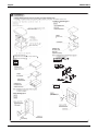
BRC1E71 Navigation Remote Controller (Wired Remote Controller) .......... 3
BRC4C / 7C / 7E Wireless Remote Controller / Receiver .......................... 12
BRC2A71 Simplified Remote Controller..................................................... 14
DCS302C71 Central Remote Controller .................................................... 17
DCS301C71 Unified ON/OFF Controller.................................................... 40
DST301BA61 Schedule Timer ................................................................... 48
DCS601C71 intelligent Touch Controller ................................................... 55
3. Adapter......................................................................................................67
3.1 KRCS01-1B / 4B Remote Sensor .............................................................. 67
3.2 DTA104A53 / 61 / 62 External Control Adapter for Outdoor Unit
(Must be Installed on Indoor Units) ............................................................ 70
3.3 DTA109A51 DIII-NET Expander Adapter................................................... 73
3.4 KRP1C74 / 75 Wiring Adapter................................................................... 76
3.5 KRP4A71 / 72 / 73 / 74 Group Control Adapter) ........................................ 79
3.6 DCS302A72 Unification Adapter for Computerized Control....................... 84
Controls
1
Control Systems
EDUS391000-C
1. Control Systems
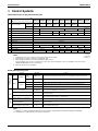
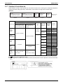
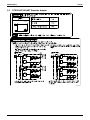
Optional Accessories of Operation Control System
Type
No.
FXFQ-PVJU
FXZQ-M7VJU FXDQ-MVJU FXMQ-PVJU
FXMQ-MVJU
FXHQ-MVJU FXAQ-MVJU
FXLQ-MVJU
FXTQ-PAVJU
FXNQ-MVJU
Item
1
Remote controller
Wireless
BRC7C812
—
BRC4C82
BRC4C82
(Note 4)
BRC4C82
Wired
2
Simplified remote controller
3
Remote sensor (Note 3)
—
BRC2A71
KRCS01-4B
4
Installation box for adaptor PCB
5
Central remote controller
BRC7E818
KRP1H98
KRCS01-1B
KRCS01-4B
KRP1B101
KRP4A96
—
—
BRC2A71
KRCS01-1B
—
BRC2A71
KRCS01-4B
KRP1C93
KRP4A93
—
KRP1B101
DTA104A62
—
DTA104A61
DTA104A53
DCS302C71
5-1 Electrical box
6
BRC7E83
BRC1E71
KJB311AA
Unified ON/OFF controller
DCS301C71
6-1 Electrical box
KJB212AA
7
Schedule timer
8
External control adaptor for outdoor unit
9
DIII-NET expander adaptor
10
Wiring Adapter
11
Group Control Adapter
DST301BA61
DTA104A62
DTA104A53
DTA104A61
DTA104A61
DTA109A51
KRP1C75
KRP4A73
KRP4A74
KRC1C74
KRP1C74
KRP1C74
—
KRP1C74
KRC1C75
KRP4A71
KRP4A71
KRP4A72
KRP4A71
KRP4A71
KRP4A74
C: 3D043022F
C: 3D068551
C: 3D068222A
C: 3TW30729-6
Note:
1. Installation box (No. 4) is necessary for each adaptor marked with an asterisk.
2. Electrical box (No. 5-1/6-1) is required for controller (No. 5/6).
3. When using the BRC2A71, remote sensor KRCS01-1B/4B is needed.
If the temperature sensor in remote controller can not sense the accuracy temperature of the room, installation of the remote sensor
KRCS01-1B/4Binstallation is also recommended.
4. Only 2 fan speeds (H, L) are available.
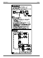
Building Management System
Part name
intelligent Touch
Controller
Basic
Hardware
Option
Software
Model No.
DCS601C71
• Air-Conditioning management system that can be controlled by a compact all-in-one unit.
DIII-Net Plus
Adapter
DCS601A72
• Add another DIII-Net line on DCS601C71.
PPD
DCS002A71
• Power Proportional Distribution.
Web/Email
DCS004A71
• Monitors and controls the air conditioning system using the Internet and Web browser
application on a PC.
HTTP
Contact/AnalogCommunication
Line
signal
Function
intelligent
Touch
Controller
DCS007A51
• HTTP interface option for Home Automation System integration.
Interface for use in BACnet®2
DMS502B71
Interface unit to allow communications between VRV and BMS. Operation and monitoring of
VRV systems through BACnet® communications.
Optional DIII board
DAM411B51
Expansion kit, installed on DMS502B71, to provide 2 more DIII-NET communication ports. Not
usable independently.
Interface for use in LON WORKS3
DMS504C71
Interface unit to allow communications between VRV and BMS. Operation and monitoring of
VRV systems through LON WORKS communication.
Unification adaptor for computerized
control
DCS302A72
Interface between the central monitoring board and central control units
Group Control Adapter
KRP4A71-74
To control the group of indoor units collectively, which are connected by the transmission wiring
of remote controller.
External control adapter for outdoor unit
(Must be installed on indoor units.)
DTA104A53, 61,
62
Cooling/Heating mode changeover. Demand control and Low noise control are available
between the plural outdoor units.
Note:
1.
2.
2
BACnet® is a registered trademark of American Society of Heating, Refrigerating and Air-Conditioning Engineers (ASHRAE).
LON WORKS is a registered trade mark of Echelon Corporation.
Controls
EDUS391000-C
Control Devices
2. Control Devices
2.1
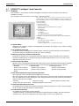
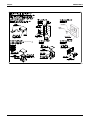
BRC1E71 Navigation Remote Controller (Wired Remote Controller)
2.1.1
Features
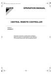
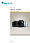
BRC1E71
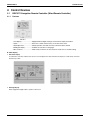
· Clear Display............................. Equipped with backlight and large sized character display and buttons.
· Stylish........................................ Basic tone is white and arrow keys are located at the center.
· Simple Operation ...................... Simple operation used with arrow keys and menu-driven method.
· Multilingual Display ................... Available for selection of 3 languages
· Other Features .......................... Wide variety of functions to meet customer needs such as schedule setting.
Clear Display
Dot matrix display
A combination of fine dots enables texts and icons to be displayed smoothly and makes the display of a wide variety of text and
illustrations possible.
Backlight display
Newly equipped backlight enables operation in dark room.
Controls
3
Control Devices
EDUS391000-C
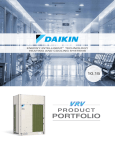
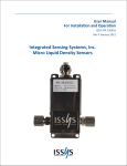
Stylish
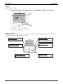
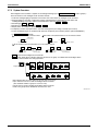
Simple and Functional Design
(1) Large text display (2) Large buttons (3) Backlight (4) No-cover design
(1)
(3)
(2)
Simple Operation
Compared to the conventional structure of button allocation for each function, the number of buttons has been decreased (from 15 to 9).
Can intuitively handle frequently performed basic operations.
(1) "Mode" button
(2) "Fan Speed" button
(3) "Menu/OK" button
4
(4) "On/Off" button
(5) "Cancel" button
(6)-(9) Arrow Keys
Controls
EDUS391000-C
Control Devices
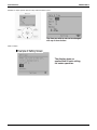
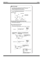
Available for simple operation with arrow keys and menu-driven system.
Available for simple operation with arrow keys and menu-driven system.
Press "Menu/OK" button to change the
screen and then the main menu appears.
Available for simple operation with arrow keys and menu-driven system.
Select the item you wish to set with direction
keys and press "Menu/OK" button at the item
you wish to set and the setting entry screen
appears.
Controls
5
Control Devices
EDUS391000-C
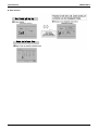
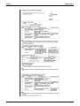
Available for simple operation with arrow keys and menu-driven system.
The item you wish to set can be changed
with up or down button.
Guide on display
The display gives an
explanation of each setting
for easier operation.
6
Controls
EDUS391000-C
Control Devices
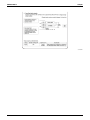
Multilingual Display
Available for display in 3 different languages.
Always available for switching display by selecting from main menu.
3 languages (English, French, Spanish)
Controls
7
Control Devices
EDUS391000-C
Other Features
8
Controls
EDUS391000-C
2.1.2
Control Devices
Functions
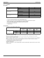
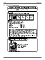
Functions
Category
Function
BRC1E71
Drawing display
Basic Functions
LCD
Operation method
Menu selection
Backlight function
Clock function (time display)
*1
Display switch function
Convenient Functions
Keylock function
Schedule (weekly) timer*4
*2
*2
*3
*3
Model name display
Contact dealer display
Maintenance/Services
Operation time display
Operational data display
: Possible
*1 Used for setting Standard Display mode or Detailed Display mode.
*2-1 When an error occurs, the error code blinks and the contact address and model names appear.
2-2 The contact address must be registered when the controller is installed.
2-3 For some models, model codes are displayed instead of model names.
*3 Can display for some model only.
*4 Setback function
Restrictions
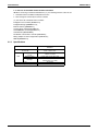
1. In the case of two remote control system.
Main
BRC1E71
Sub
BRC1D71
Wireless
BRC4***
BRC7***
BRC1E71
×
×
BRC1D71
×
Wireless
BRC4***
BRC7***
×
×
:Connectable ×:Not connectable
Due to the limited power supply capacity, there are some restrictions when controlling 2 remote controllers.
<Common restriction for SkyAir and VRV>
When controlling one indoor unit with 2 remote controllers, the remote controller operated first turns the backlight on.
When controlling 2 remote controllers, the following functions cannot be set with the sub remote controller.
1. Schedule function and Setback temperature function
2. Auto Changeover function by the remote controller
<Restriction for VRV only>
Adaptor for wiring (KRP1C*) or power supply adaptor for indoor unit PCB (X18A or X35A) cannot be used for 2 remote
controller system.
Controls
9
Control Devices
2.
1.
2.
EDUS391000-C
In the case of centralized remote controller connection.
When connecting a centralized related device (*1), the following functions cannot be set.
Schedule function and Setback temperature function
Auto Changeover function by the remote controller
(*1) this means all centralized remote controller.
intelligent Touch Controller [DCS601C71]
intelligent Manager [DAM602A71,72]
BACnet Gateway [DMS502B71]
Central remote controller [DCS302C71]
Unified ON/OFF controller [DCS301C71]
Schedule timer [DST301BA61]
Residential central remote controller [DCS303A71]
Wiring adaptor for electrical appendices [KRP2A5*/6*]
DMS-IF [DMS504C71]
2.1.3
Specifications
New Remote Controller
BRC1E71
Dimension (in.)
H×W×D
LCD
10
4’3/4” × 4’3/4” × 3/4”
Display size (in.)
H×W
1’25/32” × 2’13/16”
Display method
Full dot method (dot 160 × 255)
Backlight
Yes
(Background color: white)
Color
Fresh white
Cover for operation part
No
Controls
EDUS391000-C
2.1.4
Control Devices
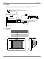
Dimensions
Unit (in.)
IF THE HOLE SIZE IS TOO LARGE OR THE LOCATION NOT PROPER,
THE WIRE MAY COME OUT OF THE HOLE IN THE REMOTE CONTROLLER.
3D065275
2.1.5
Applicable Models
Applicable Models
Applicable Indoor unit
Controls
VRV
All models that can be connected
BRC1D71
SkyAir
All models that can be connected
BRC1D71
11
Control Devices
2.2
EDUS391000-C
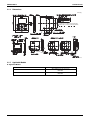
BRC4C / 7C / 7E Wireless Remote Controller / Receiver
BRC7C812
6-3/16
Unit (in.)
2-7/16
11/16
C:3D005912D
BRC4C82
6-3/16
4-3/4
Unit (in.)
2-3/4
11/16
1/32
1-3/8
4-3/16
3-9/16
3-5/16
2-3/16×3/8
2-13/16
2-7/16
11/16
1-15/16
C:3D007898B
12
Controls
EDUS391000-C
Control Devices
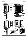
BRC7E83
Unit (in.)
3D049336
BRC7E818
6-3/16
Unit (in.)
2-7/16
11/16
C:3D034905B
Controls
13
Control Devices
2.3
EDUS391000-C
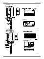
BRC2A71 Simplified Remote Controller
2.3.1 Name and Function
6
13
2
1
3
5
H L
F
7
4
8
9
11
10
12
BRC2A71
REMOTE CONTROLLER: NAME AND FUNCTION OF EACH SWITCH AND DISPLAY
DISPLAY “
CONTROL)
ON/OFF BUTTON
�
�
Press the button and the system will start. Press the
button again and the system will stop.
OPERATION LAMP (RED)
�
The lamp lights up during operation. Blinks in case of stop
due to malfunction.
DISPLAY Ò
CONTROL)
�
Ó (CHANGEOVER UNDER
It is impossible to changeover heating/cooling with the
remote controller when it shows this display. (As for details,
see “SETTING OF MASTER REMOTE CONTROLLER” in
the installation manual attached to the indoor unit.)
DISPLAY Ò
�
F
This display shows the set temperature. Only given during
a cooling or heating operation.
”“
”“
”
This display shows current OPERATION MODE.
“ ” is not available with outdoor units specially designed
for cooling only.
“
” is reserved only for outdoor units capable of heat
recovery.
L
” (FAN SPEED)
” (DEFROST / HOT START)
Indicates that defrost or hot start (during which the fan is
stopped till the temperature of air supply rises enough at
the start of a heating operation) is in progress.
TEMPERATURE SETTING BUTTON
��
” (SET TEMPERATURE)
DISPLAY “ ” “ ” “
(OPERATION MODE)
�
�
H
This display shows the fan speed: HIGH or LOW.
DISPLAY “
Ó (VENTILATION/AIR
This display shows that the total heat exchanger and the
air cleaning unit are in operation. (These are optional
accessories).
DISPLAY “
�
When this display shows, the system is UNDER
CENTRALIZED CONTROL.
(This is not a standard specification)
DISPLAY “
�
” (UNDER CENTRALIZED
Use this button for SETTING TEMPERATURE of the
thermostat.
; Each press raises the set temperature by 1 ˚F.
; Each press lowers the set temperature by 1 ˚F.
The variable temperature range is between 60 F and 90 ˚F.
FAN SPEED CONTROL BUTTON
��
��
Press this button to select the fan speed, HIGH or LOW,
of your choice.
OPERATION MODE SELECTOR BUTTON
Press this button to select OPERATION MODE.
DISPLAY “
��
” (MALFUNCTION)
Indicates malfunction and blinks if the unit stops operating
due to malfunction.
(As for details, see “TROUBLE SHOOTING” in the
operation manual attached to the outdoor unit.)
For the sake of explanation, all indications are shown in the figure above contrary to actual running situations.
3P146204
14
Controls
EDUS391000-C
Control Devices
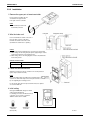
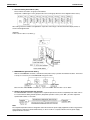
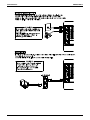
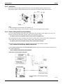
2.3.2 Installation
1. Remove the upper part of remote controller.
Insert a minus screwdriver into the
slot between the upper and the
lower part of remote controller.
NOTE
1. Do not directly touch the PC
board with your hand.
2. Wire the indoor unit.
Connect terminals P1 and P2 on the rear of
the lower part of remote controller to
terminals P1 and P2 on the indoor unit.
(Terminals P1 and P2 have no polarity.)
NOTES
1. The electric parts box and wiring for connection are not included.
2. When wiring, run the wiring away the power supply wiring in order to
avoid receiving electric noise (external noise).
3. When wiring, refer to the wiring diagram of indoor unit (attached to
indoor unit) as well.
WIRING SPECIFICATION
Wiring type
Sheathed wire (2 wire)
Size
AWG18 or AWG16
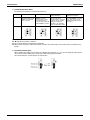
3. Fasten the remote controller.
Attach the lower part of remote controller to the electric parts box
(part to be procured in the field).
NOTE
Choose the flattest place possible for the mounting surface. Be
careful not to distort the shape of the lower part of remote controller
by over-tightening the mounting screws.
For the electric parts box to be procured in the field, use optional
accessories KJB111A.
4. Initial setting
Change the MAIN/SUB changeover switch
setting as described below.
If controlling one indoor unit with two remote
controllers, set one remote controller to
"MAIN." and the other to "SUB."
Main Remote
Controller
(Factory Set)
Controls
Sub Remote
Controller
3P146205-1
15
Control Devices
EDUS391000-C
NOTES
2If controlling with one remote controller, be sure to set it to "MAIN."
2Set the remote controller before turning power supply on.
"
" is displayed for about one minute when the power supply is
turned on, and the remote controller cannot be operated in some cases.
5. Reattach the upper part of remote controller.
NOTE
1. Do not directly touch the PC board with your hand.
3P146205-2
2.3.3 Dimensions
Unit (in.)
3D047341
16
Controls
EDUS391000-C
2.4
Control Devices
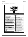
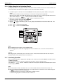
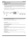
DCS302C71 Central Remote Controller
You can connect up to 64 groups of indoor units (max.
128 units); let’s you operate or monitor ON/OFF,
temperature setting, etc., by zone individually or
together.
Up to 2 units are connectable within 1 system (Up to 4
units in case of the double central control mode)
Executes zone control for up to 64 zones and is
designed for operation efficiency.
Error contents are displayed in code; maintenance and
inspections can be quickly carried out.
1 schedule timer and up to 4 unified on/off controllers
can be connected to a single unit, and you can freely
extend the central control system according to building
size and purpose.
Applicable wiring methods include bus and star in
addition to series wiring
2.4.1 System Configuration
System Outline
Controls
17
Control Devices
EDUS391000-C
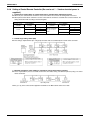
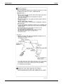
System Configuration (Group / Zone Control)
Group control
The group means the indoor units connected by the same control wiring for remote controller (connected to terminal
P1 and P2) and all the unit in group have “the same setting” and “the same operation”.
The indoor units in the group are controlled by the remote controller for indoor unit.
The number of indoor units in one group is up to 16 units.
Zone control
The zone means the indoor units connected by the same control wiring for central remote controller (connected to
terminal F1 and F2) and all the unit in zone have “the same setting”.
The zone control of the indoor unit is operated by the central remote controller.
From 1 up to 64 zones can be controlled by the central remote controller.
The number of groups you can set in one zone is from 1 up to 64 groups.
Up to 16 units can be set in one group, and up to 64 groups (up to 128 units) can be connected.
18
Controls
EDUS391000-C
Control Devices
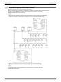
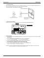
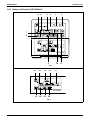
System Configuration (Control by 2 central remote controllers)
Up to 128 indoor units can be connected in one system.
2 or 4 central remote controllers are required. It is possible to control the same unit from 2 locations.
Up to 16 unified ON/OFF controllers can be connected. (8 controllers × 2 locations)
One schedule timer can be connected.
Notes:
1.Electrical power should be supplied to each central remote controller. (Single phase 100~240V)
2.When you control by 2 central remote controllers, be sure to set SS3 by the initial setting.
() When you control by 2 central remote controllers. (Last command priority)
Notes:
The following setting cannot be made by the sub side. Be sure to set by the main side.
Operation code setting
Controls
19
Control Devices
EDUS391000-C
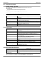
2.4.2 Specifications / Dimensions
Specifications
DCS302C71
Power supply voltage / frequency
AC100~240V ±10% 50/60Hz
Power consumption
Max. 8W
Setting data backup
Non-volatile memory (Data preserved semi-permanently)
Effects of instantaneous power failure
No effect for 20 mili-sec. or less
Forced OFF input
Operation on the local side cannot be carried out
during forced OFF input.
No-voltage normal open contact
Micro-current contact capable of handling 16VDC and approx. 10mA.
Max. 492 ft cable length
Power supply for schedule timer
Power can be supplied to schedule timer. (Max. 1 unit)
Operating ambient temperature /humidity condition
-5~40°C, 95% RH or less (no condensation)
Size (width × height × depth)
7 1/8×4 3/4×2 9/16 exposed portion of front panel: 5/8 (Unit: Inch)
Machine Weight (Mass)
Approx. 0.95 lbs
Dimensions
DCS302C71
Unit (in.)
3 5/8
1 15/16
3/16
3 5/16
4 3/4
2 13/16
5/8
7 1/8
5 3/8
C:3D043353
20
Controls
EDUS391000-C
Control Devices
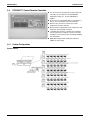
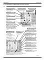
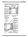
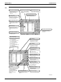
2.4.3 Names and Functions of Operating Part
Display part DISPLAY (OPERATION MODE) Displays operating state.
DISPLAY(VENTILATION
CLEANING DISPLAY)
This is displayed when a Ventiair
total enthalpy heat exchanger unit
or other such unit is connected.
DISPLAY (OPERATION
MODE)
Displays operating state.
OPERATION LAMP (RED)
Lit while any of the indoor
units under control are in
operation.
UNIFIED OPERATION
BUTTON
Press to operate all indoor
units.
UNIFIED STOP BUTTON
Press to stop all indoor
units.
DISPLAY (TIME TO CLEAN)
It lights up when any individual unit
(group) has reached the time for the
filter or element to be cleaned.
DISPLAY (REFRIGERANT
SYSTEM DISPLAY)
This indication in the square is lit
while the refrigerant system is
being displayed.
DISPLAY (COOLING/HEATING
SELECTION PRIVILEGE NOT
SHOWN)
DISPLAY (ZONE SETTING)
ALL
INDIVIDUALLY
The lamp is lit while setting zones.
OPTION
TEST
12
F
C
DISPLAY (OPERATION MONITOR)
SET
The lamp is lit while operation is
being monitored.
NOT
T
L H HH
AVAILABLE FRESH UP
No..
CODE
UNIT No.
DISPLAY
The status displays indicates either
batch functions or which zone or
individual unit (or group) are being used.
For zones or individual units (groups)
for which this is displayed, cooling and
heating cannot be selected.
DISPLAY (UNDER HOST COMPUTER
INTEGRATED CONTROL)
While this display is lit up, no settings
can be made. It lights up when the upper
central machines are present on the
same air conditioning network.
DISPLAY (TIME NO.)
Displays the operation timer No.
when used in conjunction with the
schedule timer.
OPERATION MONITOR
Each square displays the state
corresponding to each group.
DISPLAY (OPERATION CODE
AND UNIT NUMBER DISPLAY)
DISPLAY (PRESET
TEMPERATURE)
Displays the preset temperature.
The method of operation (remote
controller prohibited, central operation
priority after-press operation priority,
etc.) is displayed by the
corresponding code.This displays the
numbers of any indoor units which
have stopped due to an error.
DISPLAY (VENTILATION
STRENGTH/SET FAN
STRENGTH DISPLAY)
DISPLAY (MALFUNCTION CODE)
This displays (flashes) the content
of errors when an error failure has
occurred.In maintenance mode, it
displays the latest error content.
This displays the set fan
strength.
"NOT AVAILABLE" DISPLAY (NO
FUNCTION DISPLAY)
If a function is not available in the
indoor unit even if the button is
pressed, "NOT AVAILABLE" is may
be displayed for a few seconds.
DISPLAY (FAN DIRECTION
SWING DISPLAY)
DISPLAY (TIME TO CLEAN AIR
CLEANER ELEMENT/TIME TO
CLEAN AIR FILTER)
This displays whether the fan
direction is fixed or set to
swing.
Displayed to notify the user it is time
to clean the air filter or air cleaner
element of the group displayed.
DISPLAY (INSPECTION/TEST)
Pressing the maintenance/test run
button(for service) displays this. This
button should not normally be used.
Control Section
ON/OFF BUTTON
ALL/INDIVIDUAL BUTTON
Pressing this button scrolls through
the "all screen", "zone screen", and
"individual screen".
Starts and stops ALL,
ZONE, and INDIVIDUAL
units.
FAN DIRECTION
ADJUSTMENT BUTTON
OPERATION MODE
SELECTOR BUTTON
This button is pressed when
setting the fan direction to
"fixed" or "swing".
This sets the operation
mode. The dry setting
cannot be done.
TIME NO. BUTTON
Selects time No. (Use in conjunction
with the schedule timer only).
CONTROL MODE BUTTON
VENTILATION MODE BUTTON
Selects control mode.
This is pressed to switch the
ventilation mode of the total
enthalpy heat exchanger.
FILTER SIGN RESET BUTTON
This button is pressed to erase the
"clean filter" display after cleaning or
replacement.
VENTILATION STRENGTH
ADJUSTMENT BUTTON
This button is pressed to switch the
ventilation strength ("fresh up") of
the total enthalpy heat exchanger.
SET BUTTON
Sets control mode and time No.
INSPECTION/TEST RUN BUTTON
(FOR SERVICE)
Pressing this button scrolls through
"inspection", "test run", and
"system display". This button is not
normally used.
Controls
ARROW KEY BUTTON
ZONE SETTING BUTTON
This button is pressed
when calling an individual
indoor unit or a zone.
Zone registration mode can
be turned on and off by
pressing the start and stop
buttons simultaneously for at
least four seconds.
TEMPERATURE
ADJUSTMENT BUTTON
(ZONE NUMBER BUTTON)
FAN STRENGTH ADJUSTMENT
BUTTON
Pressing this button scrolls through
"weak", "strong", and "fast".
This button is pressed when
setting the temperature. Select
the zone number if any zones
have been registered.
21
Control Devices
EDUS391000-C
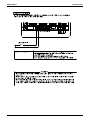
2.4.4 Description of Functions
Individual Screen, all Screen, Zone Screen
This controller can perform operations in the individual screen, all screen, or zone screen.
Individual screen
The individual screen is used when performing group operations.
All screen
The all screen is used when performing operations for all units at once.
Zone screen
The zone screen is used when performing zone operations.
Basic Functions
Individual/Zone control
Unified ON/OFF
Malfunction code display
Connection of unification adaptor for computerized
control
Remote control acceptance/rejection
2 central controllers
Descriptions of outline
Up to 64 groups (Max. 128 units and max. 16 units per group) of indoor units and HRV units can be controlled by
individually or by zone.
ON/OFF can be set for each zone, and can be controlled simultaneously for entire system by push button or by contact
signal from outside.
The status of each group is always displayed, such as ON/OFF, error, etc. If the error occurs, it displays the contents of
error by malfunction code through the self-diagnosis function.
By connecting the unification adaptor for computerized control (option), it can be linked with the central monitoring panel
and etc. by contact signal, which enables you to operate ON/OFF simultaneously or monitor the operating status.
It is possible to restrict the function of local remote controller.
(Only ON operation rejection, or ON/OFF operation rejection)
By connecting two central remote controllers, the same air-conditioner can be controlled from 2 locations (By tenant or
administration office.)
Zone Control Functions
Zone control
Up to 64 zones
Zone register
Zone setting
ON/OFF control of zone
Maintaining zone setting
Cool/Heat changeover by zone
Batch operation
No local remote controller
Combination with other controllers
Connection to central monitoring panel
Descriptions of outline
The zone function is a function to control one or more group of air-conditioner, and the operation setting such as ON/OFF
etc. can be made by zone.
Up to 64 zones (64 groups for each zone) can be set. However, the group setting spreading over the plural zone cannot
be set.
When the power is supplied first time, each group is registered in each respective zone. If you can simply register the
several groups in the same zone by switch, so that you can have simultaneous operation of the units in that zone
immediately. (The operation of temperature setting and etc. is also controlled by zone simultaneously.)
By adding the zone setting function (Zone “0”) from the central remote controller, you can set the same setting for all the
zone registered by single operation.
For example, if there are three groups in one room and if you register these three groups as one zone, you can operate
these three groups simultaneously by single operation (ON/OFF, temperature setting etc.).
You still can operate each group individually by local remote controller.
Even if the power is turned off, the zone configurations set are maintained semi-permanently. (saved in non-volatile memory)
The cool/heat changeover can be made by zone. However, it is required to have a master group for Cool/Heat changeover
in that zone.
The same setup is possible at one operation to all the groups registered on the "All" screen.
Even if there is no local remote controller, you can still perform the same operation. There is no problem even if no remote
controller is connected. (However, in this case, each one air-conditioner consists of one group.)
You can also combine with a unified ON/OFF controller and a schedule timer.
(Refer to the system configuration for details.)
You can also combine with an Interface for use in BAC net and a data station in order to connect to the central monitoring
panel. A parallel interface can also be connected.
Cool/Heat Changeover and Eligibility Setting
Possible control
Remote controller acceptance/rejection
"NOT AVAILABLE" DISPLAY
(NO FUNCTION DISPLAY)
Descriptions of outline
The operation mode of the outdoor unit can be changed by the local remote controller or by the central remote controller.
(For test operation, change setting of cool/heat selector switch of the outdoor unit.)
You can set the remote controller acceptance/rejection on the central remote controller by the local remote controller.
If a function is not available in the indoor unit even if the button is pressed, "NOT AVAILABLE" is may be displayed for a
few seconds.
Note:
Refer to the next page for the selection of cool/heat mode (eligibility for cool/heat changeover).
22
Controls
EDUS391000-C
Control Devices
Cool/heat Selection Eligibility Setting by Remote Controller for Indoor Unit
The outdoor unit of can freely be selected the operation mode (fan, dry, auto [Heat Recovery only], cooling or heating) by
the remote controller for indoor unit. However, you have to set the selection eligibility for fan, dry, cooling and heating
operation on the one of the remote controller out of the indoor units connected to the outdoor unit. For Heat Recovery
series and the function unit (for heat recovery), if 2 or more indoor units are connected to one Branch Selector unit, you
have set the selection eligibility for fan, dry, auto, cooling and heating operation on the one of the remote controller out of
the indoor units connected to the Branch Selector unit.
(Only the remote controller having the selection eligibility can change the operation mode.)
Heat Recovery series
Branch Selector unit
Indoor unit
Setting method of the selection eligibility for cool/heat
1. Preparation
When turning on the power first time, "CHANGEOVER UNDER CONTROL" sign blinks.
When you set;
Continue to push Operation switch
for about 4 seconds.
sign blinks on all the indoor units
connected to the outdoor unit or
Branch Selector unit.
2. Selection Eligibility
Setting
2
Push Operation switch of the remote
controller, which you want to set the
selection eligibility. This completes the
setting procedure. Cool/heat selection
eligibility is set for that remote controller,
and
sign goes off.
still blinks on all other remote
controllers.
3
Push Operation switch of remote
controller having the selection
eligibility (The remote controller not
displaying
sign) several times
to select the desired operation mode.
[Fan], [Dry], [Auto](only for Heat Recovery
series),[Cooling] and[Heating] mode are
selected each time you push the
[Operation switch]. Operation mode of
other remote controllers, which has no
selection eligibility, is also switched
automatically.
1
Operation
ON/OFF
3. Operation mode
changeover
Controls
23
Control Devices
EDUS391000-C
Description of operation and its function
� Remote control having the
selection eligibility
Remote controller having
no
sign.
(
� Remote control having the
selection eligibility
Remote controller having
no
sign.
(
Set to Cooling, Heating
and Auto (only for Heat
Recovery series);
Other remote controller
controller having
( Remote
)
no
sign.
)
Set to [Fan];
)
Other remote controller
controller having
( Remote
)
no
sign.
• Changes to the operation mode
selected by the remote controller
having the selection eligibility.
• However, you can still change to
[Fan], or change from [cooling] to
[dry].
• Can only be set to [Fan].
It
is also possible to set the selection eligibility on the wireless remote controller.
It is not possible to set to "Dry" with the Central Remote Controller.
Control with Two Central Remote Controllers
The central remote control equipment is newly designed to "B" type, which has been added with a new control function
for 2 central remote controllers. However, be sure that the relation between Main/Sub of the central remote controller is
different from those of local remote controllers.
Note:
Understand that if the timer No. is registered by the sub-central remote controller, it will be overidden by the Main remote
controller setting upon operation. [Timer mode acceptance for local remote controller (mode no. 8,9,18, and 19)]
<Explanation of the above figure>
If you operate the central remote controller in the sequence of N and O, the indoor unit is set for cooling / temperature
setting 75°F.
However, the display of zone setting of the master remote controller remains at heating / temperature setting at 80°F.
<Cautions>
Operation code cannot be set by the sub central remote controller.
Combined zone operation can only be set by zone registration of the main central remote controller.
Both main and sub central remote controller are operated by a last priority command for the functions other than the
above.
However, the display on the central remote controller cannot be changed by each other. (On the display for the group,
you can monitor the present operation status.)
24
Controls
EDUS391000-C
Control Devices
Sequential Start
<Operation command from central control equipment>
Each unit operates in sequence. For example, if you set the simultaneous operation by the central remote controller,
which controls 1-00 ~ 4-15 and 5-00 ~ 8-15 groups, two outdoor units start simultaneously.
Registering Zone
It is possible to set multiple groups as one zone and control each zone separately.
No zones are registered when the unit is shipped from the factory.
Zone registration can be done in the individual screen, all screen, or zone screen.
2
9
5
6
1
3
4
7
8
Registration
1. 1 Pressing the "ALL/INDIVIDUAL" button for four seconds. 2 Displays ZONE SET.
Zone Number 1 will be displayed, and if there are any groups already registered in the displayed zone, a “
light up on the operation monitor.
2. 3 Select the Zone Number to be registered using the "ZONE NUMBER" button.
Keeping the button pressed down will move it rapidly.
3. 5 "
"to the group you wish to 4 register using the arrow keys.
Keeping the button pressed down will move it rapidly.
4. 6 Press the "SELECT" button to register that group to the zone.
The "
" display lights up on all the selected units.
7
Pressing the "RESET" button removes the group from that zone, and "
" goes off.
Repeat steps 3 and 4 until all the units you wish to register to the zone have been added.
” will
2
In this example, a screen is shown with units 1-00, 1-02, 1-03, and 2-00 registered to Zone Number 1.
5. Repeat steps 2 to 4 to register to the next zone.
6. Once zone registration is complete, 1 press the "ALL/INDIVIDUAL" button to turn off "ZONE SET" display
and return to the individual screen.
The display returns to the normal screen if nothing is done for one minute when in zone registration mode.
(NOTE)
It is impossible to register one group to several different zones.
If this is done, the last zone registered to will be valid.
Controls
25
Control Devices
EDUS391000-C
Batch deletion of zone registration
1.
9
Pressing the "ALL
" for at least four seconds while 8 pressing the "FILTER SIGN RESET" button
when 2 "ZONE SET" is displayed will delete all zone registrations.
The zone registrations for all units will be lost.
Zone setting
Set the screen of [Zone 0] on the display, and if you set the following mode, you can set to all the registered zone on the
central remote controller by one operation.
Operation mode
Control mode
Room temperature setting
Time No.
Display of "NOT AVAILABLE"
If indoor units are not available for functions subject to control even when attempting to operate these functions from
DCS302C71, the system will display this "NOT AVAILABLE" message.
This message is displayed for a period of approximately two seconds. However, if any button corresponding to functions
not available while the "NOT AVAILABLE" is displayed, it will be displayed for a period of another approximately two
seconds.
Monitor in zone unit
Operating and monitoring the system even in group or zone unit has become enabled from the DCS302C71.
Monitoring in zone unit is conducted taking an indoor unit with a lower address within the zone as the Main Indoor Unit.
For monitoring the zone settings:The following screens are displayed.
Outdoor Unit
Zone 1
Central Remote
Controller
Indoor Unit
1-00
2-00
Zone 2
1-01
Zone 4
1-02
3-00
4-00
1-03
1-04
Zone 3
1-05
1-06
Main Indoor Unit
Operation Code
Timer No.
Temp. Display
Operation Mode
Zone 1
1-00
1-00
1-00
1-00
Zone 2
1-03
1-03
1-03
1-03
Zone 3
1-06
1-06
1-07
1-07
Zone 4
2-00
2-00
N/A
N/A
1-07
1-08
If the system is operated on the Zone screen, one and the same setting will be made on all indoor units registered with
the zone.
On the Zone screen, ventilation mode is only monitored. In order to change ventilation mode, be sure to use the
Individual screen.
On the Batch screen, operating and monitoring is also enabled, thus monitoring an indoor unit with a lower address
within the scope of control.
26
Controls
EDUS391000-C
Control Devices
Changing the Fan Direction and Fan Strength
This changes the fan direction and strength settings in the air conditioner.
Changing the fan direction and strength is done in the individual screen.
2
4
INDIVIDUALLY
80
F
L
5
1
3
6
[Registration]
1. 1 Press the "ALL/INDIVIDUAL button" to enter the 2 individual screen.
The unit will enter the individual screen automatically if nothing is done for one minute.
2. 3 Using the arrow keys, 4 move the "
" to select the units to fan direction adjustment or fan strength
adjustment.
Keeping the button pressed down will move it rapidly.
3. 5 Press the "FAN DIRECTION ADJUSTMENT" button.
This sets "fixed" or "swing" for the fan direction.
6
Press the "FAN STRENGTH ADJUSTMENT" button.
Pressing this button scrolls through "
Depending on the indoor unit, only "
L
L
", "
H
" and "
" and "
H
HH
".
" may be available.
The functions included in the indoor units may vary. Pressing a button for a function which is not available will cause
"NOT AVAILABLE" to be displayed.
Timer Number Setting
(Only when used with the schedule timer)
Using this together with the schedule timer makes it possible to set on and off times four times a day.
4 times of ON/OFF time can be setup per day. Because, two settings of ON/OFF time are possible to one Schedule
Timer and two Schedule Timers can be registered into a Central Remote Controller.
INDIVIDUALLY
1
2
No.
F
L
1
2
Controls
27
Control Devices
EDUS391000-C
[Registration]
1. 1 Pressing the "TIMER No." button causes the number set for timer number 1 to blink.
If no timer setting has been made " " will be displayed. Select the desired timer number by pressing the
1
"TIMER NO." button.
1
2
No.
No
2.
2
Once the desired timer number is displayed, press the "SET" button.
Press the 2 "SET" button within 10 seconds after the timer number is displayed.
The display will return to how it was after 10 seconds.
The display for timer number 1 will stop blinking and then timer number 2 will start blinking.
1
2
No.
No
3.
1
Select the desired timer number by pressing the "TIMER NO." button.
Once the desired timer number is displayed, 2 press the "SET" button.
The display for timer number 2 will stop blinking.
The " No.
No " display will disappear after 3 seconds.
Select " " in the timer number when you do not wish to set a timer number.
It is possible to set only one timer number.
(The times for turning the unit(s) on and off twice a day can be set with a single timer number.)
1
2
No.
No
Timer number setting
Group control: select the unit in the individual screen and set the timer number.
Batch control: set the timer numbers for all connected units.
Zone control: set the timer numbers for all zone-registered units.
Call up the zones which you wish to set in the zone screen and set the timer numbers.
Since the timer number will be set to after-press priority, the timer number in the last screen set will be
valid for the connected units.
Example 1
Setting timer number 1 for unit 1-00 to "1" and timer number 2 to "2" in the individual screen and then setting timer
number 1 to "3" and timer number 2 to "4" in the batch screen causes the timer numbers for all units to be set, so
timer number 1 for unit 1-00 will be "3" and timer number 2 will be "4".
Example 2
To prevent leaving units on, timer number 1 is set to "5" in the batch screen.
Setting timer number 1 in zone number 1 to " " in the zone screen after that will change the timer number for zone
number 1, so the setting to prevent leaving the units on will be lost for zone number 1 only.
If a timer number is set incorrectly by accident, redo the setting in the desired screen.
What happens when the timer number on time and off time are set to the same time
When the on time and off time are set to the same time for the same timer number, operation does not change.
When the on time and off time are set to the same time for different timer numbers, the off time is given priority.
When using timer operation, make sure the times do not overlap when setting the program of the schedule timer.
28
Controls
EDUS391000-C
Control Devices
2.4.5 Wiring Instructions
Wiring instructions
For control wiring of DIII-NET, you can select from the following 3 types of wiring methods.
1. Series method :
Wiring is connected by a single line from the central controller.
2. Bus method :
Up to 16 branches is possible. Never diverge the sub-branches from the branch line.
3. Star method :
Up to 16 branches is possible. Never diverge the sub-branches from the branch line.
Specifications of Transmission Wiring
Be sure to use either 2-core sheathed vinyl cord or cable as mentioned below. The size of wire should be selected in the
range of AWG 18 or AWG 16.
<Length of control wiring>
Between central remote controller and air-conditioner
Maximum extension : 3280 ft, Total length : 6560 ft ()
When you have branches, be sure the total length includes all the branches.
Controls
29
Control Devices
EDUS391000-C
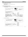
2.4.6 Instructions for Initial Setting
Group No. Setting for Central Control Equipment
Group No. should be set for each group by the remote controller for indoor unit, when you operate the system with
central remote controller and unified ON/OFF controller. (For the same control group, set only one of the unit.)
Remote controller for indoor unit
1. Turn ON the power of the indoor unit and central remote
controller.
(Unless the power is ON, no setting can be made.)
Check that the installation and electrical wiring are correct
before turning the power supply ON.
(When the power supply is turned ON, all LCD appear
once and the unit may not accept the operation for about
one minute with the display of “88”.)
2. While in the normal mode, hold down the “
” button
for a minimum of 4 seconds.
The remote controller will enter the FIELD SET MODE.
3. Select the MODE No. “00” with the “
” button.
4. Use the “
” button to select the group No. for each
group.
(Group numbers increase in the order of 1-00, 1-01, ... 115, 2-00, ... 4-15.)
5. Press “
” to set the selected group No.
6. Press “
” to return to the NORMAL MODE.
UNIT NO.
3.
4.
5.
6.
Simplified remote controller
Group No. setting by simplified remote controller.
Remove the cover of remote controller.
While in normal mode, press the [BS6] BUTTON (field
set) to enter the FIELD SET MODE.
Select the mode No. [00] with [BS2] BUTTON
(temperature setting ) and [BS3] BUTTON (temperature
setting ).
Select the group No. with [BS9] BUTTON (set A) and
[BS10] BUTTON (set B). (Group Nos. increase in the
order of 1-00, 1-01......1-15, 2-00,.....4-15. However, the
unified ON/OFF controller displays only group No. set
within the range of control.)
Press [BS7] BUTTON (set/cancel) to set group No.
Press [BS6] BUTTON (field set) to return to the NORMAL
MODE.
MODE NO.
SECOND
CODE NO.
Unit NO.
FIELD
SET
MODE
SETTIING
FIRST
CODE NO.
TEST
2·6
30
1.
2.
5
4
3
Controls
EDUS391000-C
Control Devices
<Cautions>
Even in the system without remote control, connect the remote controller once to set group No. for central control
equipment and remove the remote controller after setting.
When you set the group No., be sure to supply the power to the central remote controller, the unified ON/OFF
controller and the indoor unit.
<Example of group setting>
Cautions
When the power is supplied, all the display appears once on the remote controller and then the display changes to [88]
for about one minute and during that time the remote controller does not function. However, this is not a malfunction of
remote controller.
Control Mode Setting by Remote Controller (Field Setting)
The control mode defines the function of local remote controllers to handle various types of control and applications.
Function can be defined by conditions and combinations of local remote control operations such as ON/OFF etc. (See
table below.)
Operation can always carried out from the central remote controller. (Except when connected to the central monitoring
panel.)
Description of Control Mode
The following 5 operation control modes and 20 modes combined with temperature and operation mode setting by the
remote controller are set and display by the control mode of 0 through 19.
Remote Control Rejection
For when you want to turn on/off using central remote controller only.
(On/off cannot be carried out by remote controller.)
Remote Controller Off Only Accepted
For when you want to turn on only by the central remote controller, and turn off only by local remote controller.
Central Priority
For when you want to turn on only by the central remote controller, and during the set time, turn on/off freely by local
remote controller.
Individual Priority (Last Command Priority)
For when you want to turn on/off by both central remote controller and local remote controller.
Remote Controller Permission Timer
For when you want to turn on/off by local remote controller during set time, but you do not want to start operation from
the central remote controller at the programmed time of system start.
Note:
The control mode consists of numbers 0 through 19, but only 0 through 9 are usually set.
Controls
31
Control Devices
EDUS391000-C
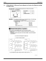
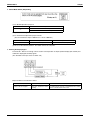
2.4.7 Selection of Control Mode No.
Select whether to accept or reject operations by local remote controller such as Turning on/off, temperature adjustment
and operation mode setting respectively, and decide the control mode No. the right side of the table below.
(Example)
Operation from local remote
controller
(When simultaneously turned on
from central remote controller)
Operation from local remote
controller
(When simultaneously turned off
from central remote controller)
Turning off
from local
remote
controller
Temperature
adjustment from
local remote
controller
Operation mode
setting from
local remote
controller
↓
↓
↓
↓
↓
Rejection
Rejection
Rejection
Acceptance
Acceptance
Control mode
No. is "1".
Operation from remote controller
ON
Control mode Simultaneous operation,
Individual operation and
Timer operation is turned
“ON” by central controllers
Simultaneous operation
and timer operation is
turned “OFF” by central
controllers
OFF
Temperature
adjustment
Rejection
Remote
controller
rejection
Rejection
(example)
Acceptance
(Example)
Rejection (example)
Rejection
Remote
controller off
only accepted
Rejection (example)
Acceptance
Rejection
Central
priority
Acceptance
Acceptance
Acceptance
Individual
priority
(Last
command
priority)
Remote
controller
permission
timer
Rejection
Acceptance
Acceptance
Rejection
Acceptance (only when
timer is “ON”.)
Rejection
(only when timer is “OFF”.)
Acceptance
Operation
mode
setting
Control
mode No.
Acceptance
0
Rejection
10
Acceptance
(example)
1 (example)
Rejection
11
Acceptance
2
Rejection
12
Acceptance
3
Rejection
13
Acceptance
4
Rejection
14
Acceptance
5
Rejection
15
Acceptance
6
Rejection
16
Acceptance
7
Rejection
17
Acceptance
8
Rejection
18
Acceptance
9
Rejection
19
Notes:
: Settings when shipped from factory.
If not using remote controller, do not select the remote controller permission timer. Operation cannot be executed by
timer.
32
Controls
EDUS391000-C
Control Devices
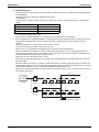
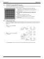
Timing Chart for Each Control Mode No. (VRV system)
Timing charts for scheduled operation and remote controller control for each control mode No. as follows.
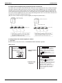
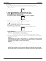
1. Remote controller rejection (Code No. 0, 1, 10, 11)
2. Remote controller off only accepted (Code No. 2, 3, 12, 13)
3. Central priority (Code No. 4, 5, 14, 15)
ON Time
DCS302C71
Command
Schedule Timer
OFF Time
Operation by Central Remote Controller
ON
OFF
ON
OFF
On
Off
ON
OFF
ON
ON
OFF
ON
Remote Controller
Command
OFF ON
OFF
On
Off
Rejection
Acceptance
Indoor Units Status
Operation by Central
Remote Controller
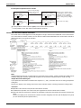
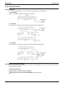
4. Individual priority (Last command priority) (Code No. 6, 7, 16, 17)
ON Time
Schedule Timer
OFF Time
DCS302C71 Command
ON
Remote Controller
Command
Indoor Units Status
Operation by Central
Remote Controller
Controls
OFF
ON
OFF
ON
Operation by Central Remote Controller
OFF
On
Off
OFF
ON
On
Off
Rejection
Acceptance
33
Control Devices
EDUS391000-C
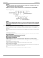
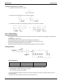
5. Remote controller permission timer (Code No. 8, 9, 18, 19)
It switches to the cord of "Remote Controller Permission Timer"
Operation Cord
ON Time
Schedule
OFF Time
ON Time
Schedule
OFF Time
Remote Controller
Permission Timer
Last command
priority
Schedule Timer
Operation by Central
Remote Controller
ON OFF
DCS302C71
Command
ON
ON
ON OFF
OFF
ON
ON OFF
OFF ON
OFF ON
Acceptance
Rejection
ON
OFF
Remote Controller
Command
Indoor Units Status
34
On
Off
Operation by remote controller is the same as central priority.
Controls
EDUS391000-C
Control Devices
2.4.8 Setting of Central Remote Controller (Be sure to set 1 ~ 3 before electrical power is
supplied.)
1. Connector for setting "Main" for control (Connector is provided when shipped from factory)
When only one central remote controller is used, never remove the connector for setting "Main" for control.
When plural central remote controller is used or central remote controller is used with other central controllers, the
setting should be made according to the following table.
Pattern of central control equipment connection.
Central remote
controller
1~4 units
Unified ON/OFF
controller
Schedule timer
—
—
1~16 units
—
—
1 unit
1 unit
Connector for setting Main for control (Presence of connector)
Central remote
controller
Use for 1 unit only.
Not use for other
units.
Unified ON/OFF
controller
Schedule timer
—
—
Not used for all unit.
—
—
Not used.
Not used.
(However, be sure to remove the connector when the Parallel interface or Data station is used.)
2. Control range setting switch (SS3)
This setting is required when up to 128 groups of indoor units are controlled by two central remote controller.
3. Main/Sub changeover switch (Setting is required for central control from 2 locations)
This is required when you have a central control of the same indoor unit(s) from different places by using 2~4 central
remote controllers.
Either (1) or (2) of the central control equipment should be set for Main and the other one for Sub.
Controls
35
Control Devices
EDUS391000-C
4. Forced reset switch
When changing the setting of the connector for setting main controller, etc., you can reset simply by setting it to the reset
side once and returning to the normal side, without turning the power OFF.
(For normal operation, set the switch to the normal side)
5. Special Function Settings
Special functions on the central control system can be changed while in FIELD SETTING mode.
Mode No.
No. of Switch Setting
C
SET
3
1.5
2
4
Setting Procedure
1.= Press and hold the INSPECTION/TEST RUN button for a period of four seconds or more to set the system to FIELD
SETTING mode.
2.= Use the TEMPERATURE ADJUSTMENT button to select a desired Mode No.
: Press to increase the Mode No. : Press to decrease the Mode No.
3.= Press the CONTROL MODE (CODE No.) button to select a "Switch Setting No.".
4.= Press the SET button to determine the content of the setting changed.
Upon determination, the blinking the "Switch Setting No." will turn ON.
5.= Press the INSPECTION/TEST RUN button to return the system to NORMAL mode.
In this case, power supply is not needed to turn ON again.
Example: In case of no restriction items from the sub central remote controller while in double central control, make
setting of the Mode No. to "02" and the Switch Setting No. to "0".
36
Controls
EDUS391000-C
Control Devices
6. Refreshed operation
Refreshed operation is the function to transmit setting of "Temperature control", "Temperature setting" automatically
from DCS302C71.
"Refreshed operation" is "ON" when shipped from the factory.
Factory Setting
It depends on the setting of outdoor systems that an indoor unit setting is "Temperature control " or " Temperature
setting".
Outdoor Units Systems
Indoor Units Mode
Cooling Mode
Cooling 82°F
Heating Mode
Heating 72°F
Fan Mode
Fan Operation
In case of Refreshed operation is "ON"
When setting is changed by DCS302C71, it operates by this setting from the next operation.
If it sets up with 79°F in cooling by DCS302C71, next operation will also be operated at 79°F in cooling. (Even if it has
changed into heating operation, fan only operation with wired or wireless remote control, it operates at 79°F in
cooling.)
When zone registration is carried out by Central Remote Controller.
It operates from next time with the value set up in the zone.
When a zone 1 is set up with 68°F of heating. (Refer to the system of the following figure.)
When controlled by Central Remote Controller, 3 indoor units registered into the zone 1 are operated by 68°F of
heating. Because priority is given to zone setting, even if it sets up 2-02 with 77°F of heating on an individual screen
from Central Remote Controller, 2-02 is operated at 68°F.
When there are two or more indoor units in a zone.
Because an operating mode depends on the outdoor unit, the operating mode of each indoor unit does not become
the same setting.
When the outdoor unit system 1 is cooling, the outdoor unit system 2 is heating and it operates by the system of the
following figure. Setting of a zone 2 is operated in heating mode, because 2-03, 2-04, and 2-05 do not have a cooling/
heating selection right as for 79°F of cooling, but temperature setting becomes 79°F.
When you unify the operating mode of an indoor unit in the same zone, please set up a zone in the indoor unit of the
same outdoor unit system.
Zone 2
Central Remote
Controller
Outdoor Unit
System 1
1-00
1-01
1-02
1-03
1-04
1-05
2-02
2-03
2-04
2-05
Zone 1
Outdoor Unit
System 2
2-00
2-01
Cooling/Heating Selection Right
Controls
37
Control Devices
EDUS391000-C
Setting Contents and Setting No.
Mode No.
Setting contents
No. of setting switch
0
1
2
00
Setting of sequential operation function
NO
YES
–
01
Setting of refresh function
NO
YES
–
02
Setting of restriction items from sub central remote
controller while in double central control function
Disabled
Enabled
–
03
Setting of area designation for forced OFF
(Operation with T1 and T2 entered)
Forced OFF all
within the scope of
control
Forced OFF only
within the scope of
control
Forced thermostat
OFF with the scope
of control
Items indicated by boldface represent the factory set for the No. of Switch Setting.
Do not make setting of any items not listed in the table above.
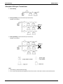
Setting for sequential start function
The central remote controller is equipped with the sequential start function, which starts the indoor units in about 2~3
seconds interval during the unified operation. (The switch is set at "ON" when shipped from factory.)
You can change the sequential start setting from "ON" to "OFF" as follows.
Note:
The sequential start function is for reducing the load of the electrical facility, but not for reducing the load of the large rush
current when the compressors are started at the same time. This is also the same for Unified ON/OFF controller and
Schedule timer.
Refresh function
This function is used to automatically send "OPERATION MODE" and "TEMPERATURE SETTING" from the central
control system while in operation. In order to disable the refresh function, set the "No. of Switch Setting" to "0".
Restriction items from sub central remote controller while in double central control function
While in double central control function, no settings of zone interlock and operation code can be made from the sub
central remote controller. In order to disable the refresh function from the sub central remote controller, set the "No. of
Switch Setting" to "0".
Setting of area designation for forced OFF
• In order to stop all indoor units within the scope of control as a single unit using the entry of T1 and T2, set the "No.
of Switch Setting" to "1".
• In order to stop all indoor units within the scope of control with forced thermostat OFF using the entry of T1 and T2,
set the "No. of Switch Setting" to "2". With this parameter set to "2", no forced stop can be made on any indoor unit.
38
Controls
EDUS391000-C
Control Devices
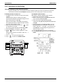
Installation
(1) Open the upper part of remote controller.
Insert a – screwdriver (2 locations) into the recess between the upper part and the lower part of remote controller and
twist the screwdriver lightly.
– screwdriver
(2 locations)
PC board is attached with both the upper and lower part of remote
controller. Do not damage the board with the screwdriver.
(2) Open the upper part of remote controller and install the Electric parts box with the attached installation screws
(M4 × 16).
Power supply wire
Do not contain the strong
current electric wire and the
weak current electric wire in
the same conduit tube.
Installation screws
(4)
Electric parts box
(KJB311AA)
Weak current
electric wire
NOTE) Suitable length of the electric wire is about 6 1/4" (from electric parts box) If it is difficult to contain a long wiring,
strip the sheathed part of the wiring.
Conduit tube
Approx. 6 1/4"
Electric parts box
Controls
39
Control Devices
2.5
EDUS391000-C
DCS301C71 Unified ON/OFF Controller
Turns up to 16 groups of indoor units (max. 128 units) on/off (operation/stop) by individual group or all at once, and lets
you check display of operation/malfunction at the same time.
For a maximum of 16 groups of indoor units (max. 128 units),
unified operation/stop or individual operation/stop can be performed
with this optional accessory. Also allows you check operation/error
display at a glance.
By combining with a central remote controller and schedule timer,
you can construct a system that matches the size and use of the
building.
Up to 8 units connectable within 1 system.
Up to 16 units in the double central control mode.
Applicable wiring methods include bus and star in addition to
crossover type.
Can be used in combination with other D-BACS equipment.
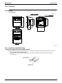
2.5.1 System Configuration
This unified ON/OFF controller enables individual and unified operation/stop for a maximum of 16 groups of indoor units.
With 2 to 8 unified ON/OFF controllers, individual and unified control is possible with up to a maximum 128 groups of
indoor units.
When using 1 unified ON/OFF
controller
When using 2 to 8 unified ON/OFF
controllers
The Unified ON/OFF Controller cannot be used in conjunction with the optional Group Control Adapter.
40
Controls
EDUS391000-C
Control Devices
The groups of indoor units are as follows:
1. One indoor unit without remote controller
2. One indoor unit controlled by one or two remote controllers
3. A maximum of 16 indoor units controlled in groups by one or two remote controllers
2.5.2 Electric Wiring
<General Instructions>
All wiring, components and materials to be procured on the site must comply with the applicable local and national
codes.
Use copper conductors only.
All field wiring and components must be provided by licensed electrician.
Unit shall be grounded in compliance with the applicable local and national codes.
Fit the power supply wiring with a fuse and a switch.
After wiring work, check power to the equipment shuts OFF when switch is shut OFF.
<Wiring Outline>
Wiring Specification
Type
Size
Power Supply Wiring
H05VV-U3G
(Note 1)
Transmission Wiring
Sheathed Wire (2 wire) (Note 2)
18-2AWG or 16-2AWG
Notes:
1. The size of power supply wiring must comply with the applicable national and local codes.
2. Allowable length of transmission wiring is as follows.
Max. 3280 ft (Total wiring length: 6560 ft)
Connect the wiring between indoor and outdoor units, indoor/outdoor units and power supply, and indoor units and
remote controllers.
For details, refer to the installation manuals of indoor and outdoor units.
Controls
41
Control Devices
EDUS391000-C
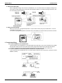
<Examples of Wiring for Transmission>
1. Series Wiring
2. Bus Type Wiring (Can be branched up to 16 branches)
Example of 3 branches
3. Star Type Wiring (Can be branched up to 16 branches)
Example of 3 branches
Note:
1. No branching is allowed after branching.
2. Use a relay terminal board (field supplied) to branch more than 3 control wires from the same terminal board.
42
Controls
EDUS391000-C
Control Devices
<Wiring to the Indoor Unit and Outdoor Unit>
Note:
Do not connect the power supply wiring to the control terminal strip. If connected by mistake, it may damage or burn
electrical parts of optional controllers for centralized control and indoor unit. It may result in serious danger. Be sure to
check wirings before turning the power ON.
2.5.3 Dimension
Unified ON/OFF Controller
DCS301C71
Unit (in.)
2 3/16×1/4
3 1/4
1 3/4
2 3/4
5/8
4 3/4
4 3/4
2 1/8
3 1/2
C:3D043640
Controls
43
Control Devices
EDUS391000-C
2.5.4 Installation
1. Open the upper part of remote controller.
Insert a minus screwdriver (2 locations) into the recess between the upper part and the lower part of remote controller
and twist the screwdriver lightly.
PC board is attached with both the upper and lower part of remote controller. Do not damage the board with the
screwdriver.
2. Open the upper part of remote controller and install the electrical box (part to be procured in the field) with the
attached installation screws (M4×16).
Note:
Suitable length of the electric wire is about 160mm from the inlet of the electrical box. If it is difficult to contain a long
wiring, strip the sheathed part of the wiring.
2.5.5 Initial Setting
1. Connector for setting master controller (X1A) (Provided with connector at factory set)
When using 1 unified ON/OFF controller, do not disconnect the connector for setting master controller. (Use the unit
with the connector in the state in which it was delivered.)
When using multiple unified ON/OFF controllers, or using the unified ON/OFF controller in conjunction with other
optional controllers for centralized control, makes settings as indicated in the right table.
Pattern of connection of optional controllers for centralized
control
Unified ON/OFF
Controller
1 to 16
Connector for setting master controller (X1A) Settings
Central Remote
Controller
Schedule
Timer
Unified ON/OFF
Controller
Central Remote
Controller
Schedule
Timer
—
—
Set one to “Used” and
all the rest to “Not
used”.
—
—
1 to 4
—
Set all to “Not used”.
(Note)
—
—
1
Set one to “Used” and
all the rest to “Not
used”.
—
“Not used”
1 to 4
1
Set all to “Not used”.
(Note)
“Not used”
Note:
For instructions on how to set the connector for setting master controller on the central remote controller, see the
installation manual provided with the central remote controller.
44
Controls
EDUS391000-C
Control Devices
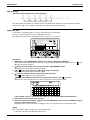
2. Switch for Setting Each Address (DS1)
These switches are used to set group control address.
Groups Nos. 1-00 through 1-15 are grouped in the same control group when the unit is shipped from the factory.
After setting, attach the number seal applicable to respective control range of the attached switch display sticker, as
shown in the diagram below.
(Example)
In The Case of 1-00 to 1-15, Attach N.
3. MAIN/SUB Changeover Switch Setting
With two unified ON/OFF controllers, centralized control (indoor units) is possible from different locations. In this kind
of set-up, it is necessary to set the MAIN/SUB changeover switch.
One of the two unified ON/OFF controllers (1) · (2) is set to “MAIN” while the other is set to “SUB”.
4. Setting of the Sequential Operation Function
The unified ON/OFF controller is equipped with a sequential operation function that sequentially turns indoor units on
in 2-second intervals during unified operation. (Sequential operation is factory set to “ON.”) To switch sequential
operation ON or OFF, set as follows.
Note:
The sequential operation function is designed to reduce the load on the power supply equipment, but does not guarantee
that compressors will not be started simultaneously, so do not count on a capacity reduction effect by power supply
equipment breaker selection.
Controls
45
Control Devices
EDUS391000-C
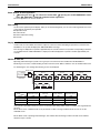
5. Control Mode Selector (DS2)
The following four patterns of control mode can be set.
Control Mode Individual
Centralized
Timer Operation Possible by
Remote Controller
ON/OFF Control Impossible
by Remote Controller
Content
After operated by unified
ON/OFF controller,
operation/stop is freely
controlled by remote
controller until stopped by
unified ON/OFF controller.
When used in conjunction
with schedule timer,
operation/stop is controlled
freely by remote controller
during the set time but
operation is not available
when schedule timer is ON.
Operation/stop is controlled
by unified ON/OFF controller
only. (This unit can not be
operated/stopped by remote
controller.)
Operation/stop is
controlled by both unified
ON/OFF controller and
remote controller.
DS2 Setting
(Factory set)
Note:
“” Indicates the position of switches.
Set control mode before turning power supply ON.
When used in conjunction with central remote controller, the control modes of the central remote controller has the
priority.
6. Forced Reset Switch (SS1)
When changing the setting of the connector for setting master controller, etc., you can reset simply by setting it to the
reset side once and returning to the normal side, without turning the power OFF.
(For normal operation, set the switch to the normal side.)
46
Controls
EDUS391000-C
Control Devices
2.5.6 Setting Group No. for Centralized Control
Set the group number of each group of the indoor unit from the remote controller. (In case of no remote controller, also
connect the remote controller and set the group No. Then, remove the remote controller.)
1. Turn ON the power of the indoor unit and unified ON/OFF controller. (Unless the power is ON, no setting can be
made.)
Check that the installation and electrical wiring are correct before turning the power supply ON.
When the power supply is turned ON, all LCD appear once and the unit may not accept the operation for about one
minute with the display of “
” flashing (an interval of ON, ON, and OFF).
2. While in the normal mode, hold down the “
” button for a minimum of 4 seconds.
The remote controller will enter the FIELD SET MODE.
3. Select the MODE No. “00” with the “
” button.
4. Use the “
” button to select the group No. for each group. (Group numbers increase in the order of 1-00, 1-01,
...1-15, 2-00, ... 8-15.)
5. Press “
” to set the selected group No.
6. Press “
” to return to the NORMAL MODE.
UNIT NO.
MODE NO.
SECOND
CODE NO.
Unit NO.
FIELD
SET
MODE
SETTIING
FIRST
CODE NO.
TEST
2·6
5
4
3
Note:
For simplified remote controller, see the installation table.
For setting group No. of HRV and wiring adaptor for other air conditioners, etc., refer to the instruction manual
attached.
NOTICE
Enter the group No. and installation place of the indoor unit into the attached installation table. Be sure to keep the
installation table with the operation manual for maintenance.
2.5.7 Confirming Operation
Before starting test operation, supply power to the indoor units, outdoor units, and unified ON/OFF controller and press
the ON/OFF BUTTON.
If the operation lamp flashes, it indicates a malfunction in the indoor unit of the applicable group.
If the display of “
” flashes, it indicates a malfunction in the optional controllers for centralized control. Check
for such malfunctions.
Note:
For test operation of indoor and outdoor units, refer to the installation manual attached with the outdoor unit.
After turning the power supply ON, if the unit does not accept operation for two minutes or more with the display of
“
” flashing, check the following points.
Check that setting of the connector for setting master controller is correct.
Check that the group No. for centralized control has been set.
Controls
47
Control Devices
2.6
EDUS391000-C
DST301BA61 Schedule Timer
Enables you to connect and control weekly schedule for up to 128 indoor units all together.
Simultaneous control of up to 128 indoor units is managed by a
week schedule.
The start and stop time for twice a day can be set for the week in
increments of 1 minute.
By combining with a central remote controller and schedule timer,
you can construct a system that matches the size and use of the
building.
If used together with a central remote controller, you can set up to 8
schedule patterns which can be distributed among zones as desired
using the central remote controller.
Is equipped with a compensation function for power failure up to 48
hours.
Features thin design of a mere 5/8" in thickness. (Uses JIS
recessed box for 2.)
Applicable wiring methods include bus and star in addition to
crossover type.
Can be used in combination with other D-BACS equipment.
2.6.1 System Configuration and Electric Wiring
With a schedule timer, you can set on/off time twice a day by units of 1 week for up to 128 indoor units.
System Configuration
If using the schedule timer alone, you do not have to set the centralized control group No. for group control.
Transmission Wiring
<Indoor Unit Wiring>
1. If using the schedule timer alone:
For the schedule timer’s power supply, connect the schedule timer (D1, D2) with the connector (X18A) on the indoor
unit PC board by crimped style terminal with the attached electric wire.
2. If using in combination with other optional controllers for centralized control:
Transmission wiring for control: AWG 18 or 16 sheathed vinyl cord or cable (2 wire) ..... Max. 3280 ft (Total Max. 6560 ft)
<Transmission Wiring Connection Example>
1 series wiring, 2 bus wiring, and 3 star wiring are the same as with the central remote controller.
48
Controls
EDUS391000-C
Control Devices
2.6.2 Names and Functions (DST301BA61)
4 6
5
3
1
2
7
8
DST301BA61
9
10
11
Fig. 1
12
15
14
16
17
DST301BA61
13
18
19
20
Fig. 2
3P124623-5C
Controls
49
Control Devices
EDUS391000-C
UNIFIED OPERATION BUTTON “
1
Press this button to perform the unified operation
regardless of the No. of programmed time.
”
The light turns on during the operation of the indoor
unit.
DISPLAY “
4
5
CLOCK ADJUSTING BUTTON “
” (TIME NO.)
PROGRAMMING START BUTTON “
DISPLAY “ OFF ” (HOLIDAY SETTING)
Lights above the day of the week set as holiday. The
operation controlled by timer is not available on that
day.
BUTTON FOR SELECTING DAYS OF A WEEK
”
15 “
Press this button to select the day of the week.
HOUR/MINUTE BUTTON “
TIMER ON BUTTON “
HOLIDAY SETTING BUTTON “
Displays the contents of malfunction during the stop
due to malfunction.
DISPLAY “
” (PRESENT TIME)
9
Displays the present day of the week and time.
DISPLAY “
” (PROGRAMMED TIME OF
10 SYSTEM START)
Displays the time programmed to start.
”
18
Press this button to set holidays.
BUTTON FOR COPYING PROGRAM OF PREVIOUS
DAY “
”
Flashes below the day of the week programmed.
8
”
17 Press this button to set the present time and the
programmed time.
DISPLAY “ — ” (SETTING OF DAYS OF A WEEK)
” (MALFUNCTION CODE)
”
16 Press this button to adjust the present time and the
programmed time.
7
DISPLAY “
”
14 Press this button to set or check the No. of
programmed time. Press it again after you are through
with the program.
Displays the time No. only when used in conjunction
with the central remote controller.
DISPLAY “PROGRAM
START.”
(PROGRAMMING START)
”
Press this button to set the present time.
The light turns on when the timer is programmed.
6
”
13
Press this button to perform the unified stop regardless
of the No. of programmed time.
OPERATION LAMP (RED)
3
TIME NO. BUTTON “
12
UNIFIED STOP BUTTON “
2
”
19
Use this button to set the No. of programmed time
same as that of the previous day.
PROGRAM CANCELING BUTTON “
”
20 Use this button to set the programmed time to cancel.
The display shows
“ – ; – – ”.
(Note)
1. Please note that all the displays in the figure appear for
explanation purpose or when the cover is open.
DISPLAY “
” (PROGRAMMED TIME OF
SYSTEM
OFF)
11
Displays the time programmed to stop.
3P124623-5C
50
Controls
EDUS391000-C
Control Devices
2.6.3 Dimension
Schedule Timer
DST301BA61
Unit (in)
1 3/4
3 5/16
4 3/4
2 13/16
5/8
4 3/4
2 3/16 × 1/4
1 7/16
3 1/2
C:3D049544
2.6.4 Installation and Initial Setting
1. Remove the upper part of the remote controller.
Insert a minus screwdriver (2 locations) into the recess between the upper part and the lower part of the remote
controller and twist the screwdriver lightly.
(The PC board is attached with the upper part of the remote controller. Do not damage electric parts with a
screwdriver, etc.)
Controls
51
Control Devices
EDUS391000-C
Attach the lower part to the electrical box (part to be procured in the field) with the provided installation screws.
(Select a flat face as an installation place. Do not tighten the installation screws excessively not to damage the lower
part of the remote controller.)
For part to be procured in the field electrical box, use KJB211AA (optional accessory).
2. Initial Setting
1. Setting connector for individual use (X1A) (Factory set : OFF) (Set for individual use only)
For individual use of schedule timer
Insert the connector attached with the body case on the PC board.
For combined use with other optional controllers for centralized control
Do not change the factory setting.
2. Control mode selector (SS2) (Set for individual use only)
By changing the switch, setting mode of individual and centralized operation is available.
Note:
When used with other optional controllers, control mode of central remote controller and unified ON/OFF controller have
the priority.
3. Setting of the sequential operation function
The schedule timer is equipped with a sequential operation function that sequentially turns indoor units on in 2second intervals during unified operation.
(Sequential operation is factory set to “ON.”)
To switch sequential operation ON or OFF, set as follows.
Note:
The sequential operation function is designed to reduce the load on the power supply equipment, but does not guarantee
that compressors will not be started simultaneously. You cannot therefore count on a capacity reduction effect by power
supply equipment breaker selection.
52
Controls
EDUS391000-C
Control Devices
4. Forced reset switch (SS1)
When changing the setting of the connector for individual use, etc., the switch can be reset simply by setting it to the
reset side once and returning to the normal side. This procedure enables to reset without turning off the power. (Set
the normal side at normal operation.)
5. Setting for special function
When you want to have a programmed operation of a part of indoor units by using only schedule timer, cut off JP1
and supply the power again.
You can have a programmed operation of the indoor units set the address for central control by local remote controller.
3. Transmission Wiring
In case of individual use of schedule timer
Connect terminals of the schedule timer (F1, F2) with terminals of the indoor unit (F1, F2). Connect terminals of the schedule
timer (D1, D2) and the connector on the indoor unit PC board, using the attached electric wire and crimp style terminals.
Prevent the connection part of crimp style terminal from getting out of the electric parts box of indoor unit.
In case of combined use with other optional controllers for centralized control
Connect terminals of the schedule timer (F1, F2, D1, D2) and the terminals of the central remote controller (or unified
ON/OFF controller).
Controls
53
Control Devices
EDUS391000-C
Wiring Specifications
F1, F2
D1, D2
Wiring
Sheathed wire (2-wire)
Sheathed wire (2-wire)
Gauge
AWG #18-#16
AWG #18-#16
Length
Max. 3280 ft
Max. 492 ft
NOTES:
1. Electrical box and transmission wiring are not attached.
2. Do not touch the PC board with your hand.
3. Keep transmission wiring at least 2 inch away from power supply wiring to avoid malfunctions.
4. Install the Upper Part of the Remote Controller as before.
2.6.5 Error Diagnosing Function
This schedule timer is provided with the malfunction diagnosing function. The malfunction code flashes if there are any
communication malfunctions between and among the optional controllers for centralized control. In addition, the
operation lamp also flashes if there are any communication malfunctions with the indoor unit. Check the contents of the
display for the problem indicators and contact your DAIKIN dealer to report the source of the problem.
Operation
Lamp
54
Malfunction (Error)
Code
Contents of Malfunction (Error)
Turn Off
M1
Failure of PC board of schedule timer.
Turn On or Off
M8
Malfunction of transmission between each optional controller for centralized control.
Turn On or Off
MA
Improper combination of optional controllers for centralized control.
Turn On or Off
MC
Address failure of schedule timer.
Blink
UE
Malfunction of transmission between indoor unit and optional controllers for centralized
control.
Blink
—
Malfunction in indoor unit (Refer to the malfunction codes of the indoor remote
controller, while also read the “CAUTION FOR SERVICING” attached to the indoor
unit.)
Controls
EDUS391000-C
2.7
Control Devices
DCS601C71 intelligent Touch Controller
2.7.1 Features
This controller is a central remote controller offering higher functionality and easier operation than the previous
DCS302C71controller.
Up to 64 groups of indoor units may be connected to 1 unit of this controller.
This controller aims to be a product positioned between the central
controlling device (central controller DCS302C71) and the I-Manager for
large scale buildings, and is a central controller most suitable for middle and
small size buildings.
< Products Features >
1. High Level Functions
· Annual schedule control
· Electricity proportional distribution function (option)
· D-Net function
2. Easy Operation
· Color liquid crystal
· Icon display
· Touch panel application
· Air conditioner name and zone name input available
3. DIII-NET × 1 line (64 units) and another line (64 units) with DIII-NET Plus
Adapter.
4. Saving expenses
· Controlling personnel not required
· Energy saving schedule
· Functions equal to those of a compact monitor panel
Operation Menu
intelligent Touch Controller is capable of starting/stopping of the operation by the group or zone. Collective starting/
stopping is also available.
Air Conditioner Detail Setup
Temperature setting, switching between operation modes, switching of speed and direction of wind and remote
control mode setting are available by the group, by the zone or collectively.
Monitoring of Various Information on Indoor Units
Information on operation such as the operation mode and temperature setting of the indoor units, maintenance
information including the filter or element cleaning sign, troubleshooting information such as error codes can be
displayed by the group or the zone.
Diversified Operation Modes
Operation can be controlled both with the main unit and the remote control to provide diversified operation management.
Setting with the main unit allows the following remote control settings by the group, by the zone or collectively:
1. Start/Stop
2. Operation Mode
3.Temperature Setting
:(Remote control) Inhibited
:(Remote control) Inhibited
:(Remote control) Inhibited
:(Remote control) Permitted
:(Remote control) Permitted
:(Remote control) Permitted
:Priority
Zone Control Simplifying Complicated Setting Operations
Up to 128 groups can be controlled with the intelligent Touch Controller.
More than one group can be consolidated into a zone, which can be registered, to allow the following settings by the
zone. This eliminates the need for repeating the same setting operation for each group. Function to allow collective
setting for all groups is also available.
· Start/stop
· Temperature setting
· Switching between operation modes
· Setting of direction and fan speed · Disabling/enabling the remote control
Detailed Scheduled Operation Control
The intelligent Touch Controller allows detailed scheduled operation by the group or zone. Up to 8 weekly schedules
can be set. Each schedule can include up to 40 special days.
Handy Automated Control
The intelligent Touch Controller can do the following.
· Changeover Settings : automatically switches between cooling and heating according to the room temperature.
· Setback Control : prevents the temperature from rising too high or too low in unoccupied rooms.
Controls
55
Control Devices
EDUS391000-C
2.7.2 System Overview
This intelligent Touch Controller is capable of controlling/monitoring up to 64 groups of indoor units (hereafter “groups”).
The main functions of the intelligent Touch Controller include:
1. Collective starting/stopping of operation of the indoor units connected to the intelligent Touch Controller.
2. Starting/stopping of operation, temperature setting, switching between temperature control modes and
enabling/disabling of operation with the hand-held remote control by zone or group .
3. Scheduling by zone or group .
4. Monitoring of the operation status by zone or group .
5. Display of the air conditioner operation history.
6. Compulsory contact stop input from the central monitoring panel (non-voltage, normally-open contact).
7. Control and Monitoring of air conditioner with personal computer by the Controller (with the optional DCS004A71).
∗ A group of indoor units include:
1 One indoor unit without a remote control.
2 One indoor unit controlled with one or two remote controls.
Indoor unit
or
Remote control
No remote control
Remote control
3 Up to 16 indoor units controlled with one or two remote controls.
Remote control
Up to 16 units
Two remote controls
Up to 16 units
∗ Zone control with the intelligent Touch Controller
∗ Zone control, which allows collective settings for more than one group, is available with the intelligent Touch
Controller, which facilitates the setting operations.
Zone 1
Zone 2
Zone 3
Zone 4
intelligent Touch Controller
Zone 5
• One setting makes the same setting for all of the units in one zone.
• Up to 128 zones can be set with one intelligent Touch Controller.
(The maximum number of groups in one zone is 64.)
• Groups can be zoned at will with the intelligent Touch Controller.
• Units in one group can be divided into more than one zone.
3P073677-15T
56
Controls
EDUS391000-C
Control Devices
2.7.3 Options
Connecting Unification adaptor allows using the contact for normal and abnormal operation signal and collective
start/stop with a contact. For details, contact the vendor you purchased the product from.
Monitoring from PC is possible by Web
E-mail functions.
(Optional intelligent Touch Controller Web Software is necessary)
Central monitoring panel
(Collective start, stop and
Unification adaptor
error monitoring with contact) for computerized control
Outdoor unit
F1,F2
Measuring meter (max 3 units)
(Where Power Proportional
Distribution Card as option is used)
F1,F2
F1,F2
Up to 16 units maximum
CN2
LAN F1,F2
Up to 64 groups maximum
(The number of connectable indoor units is up to 64
24 VAC, Fuse(10A) switch units maximum, where the Power Proportional
L Distribution Card as option is used.)
24 VAC Com
N
Power supply
24 VAC
Grounding work
60 Hz
Force stop command
2.7.4 Specification
Specification
Power
AC24V 50/60Hz
Power consumption
10 W maximum
Force stop input
Normally-open contact
Contact current approximately 10 mA
Size
9–1/16×5–25/32×4–7/32 (W×H×D)
Mass
2 lb 10 oz
Dimension
2–1/4
3–17/32
1–31/32
5–25/32
9–1/16
The specification and appearance of the product may be modified for improvement without prior notice.
3P073677-15T
Controls
57
Control Devices
EDUS391000-C
2.7.5 Part Names and Functions
Front and Side View
PCMCIA Card Slot
Used when updating the
intelligent Touch Controller
software to a newer version.
Color LCD with Touch Panel
Touch Pen
Provides a display for monitoring
and operation.
Be sure to use the touch pen
provided for operation.
Use the touch pen for operation.
Be sure to use the touch pen for operation.
Use caution not to lose the touch pen.
When the pen is lost, contact the dealer
you purchased the product from.
NOTE
Be sure to use the touch pen for operation of the touch panel of the intelligent Touch Controller.
Operating with an object other than the touch pen provided may cause damage and failure.
3P073677-15T
Terminals on the Back of intelligent Touch Controller
Modem connector for AIRNET
Terminal block for power supply
When using AIRNET service,
connect it to the telephone line.
AIRNET service is not free, but a contract
for this service and an optional inner type
modem are required, separately.
Connect to AC24V power supply.
Terminal size is M4.
Ground terminal block
Securely connect the
ground wire.
Terminal size is M4.
LINE
PHONE
RS-232C
LAN
COM Dil
Pi3 COM Pi2 Pi1
F2
F1
L0
24
24
VAC
VAC
COM
Ethernet connector for web
Terminal block for DIII-NET communication
When monitoring and operating the indoor
units using the optional Web and E-mail
function software sold separately, connect
to LAN via Ethernet cable.
The terminal size of the terminal block
for communication with indoor units is
M3.5.
3P073677-15T
58
Controls
EDUS391000-C
Control Devices
2.7.6 Part Names on the Monitoring Screen and the Functions
Icon
Contents of the List Currently Displayed
Zone/Group Currently Displayed
When Group List is displayed
“Zone: Zone Name”
When Zone List is displayed
“Zone List Display”
The name of the zone/group currently
selected is highlighted in blue flame.
Display Mode Selection
Select between Zone and Group.
System Condition Displayed Domain
Domain displaying system
condition (Compulsory Stop etc.)
Filter/Element Sign
Displayed when there is any air conditioner
showing a filter or element sign in the zone
or the group.
Zone/Group Name
Set the names in the Group Registration or
Zone Registration in the System Setup
Mode.
Target of Automatic Control
Displayed when there is any air conditioner
with the registration of scheduled in the zone
or in the group.
Description of Zone/Group
75˚F
Set the names in the Group Registration or
Zone Registration in the System Setup Mode.
Monitoring Screen Legend
Displayed Abnormality in Air Conditioner or Communication
Pressing the “?” button shows more detailed
legend.
Blue triangular mark shows communication abnormality in
air conditioner.
Yellow triangular mark shows abnormality in air conditioner.
Information on Zone/Group Currently Displayed
Generally, the temperature setting and the
operation mode are displayed. If any error
occurs in the air conditioner, the error code is
displayed.
Display for Collective Monitoring of Air
Conditioners Connected to intelligent Touch Controller
When operation is normal and any air
conditioner is in operation:
Red/Normal
When operation is normal and all air
conditioners are in stoppage:
Green/Normal
When there is any air conditioner generating
an error:
Yellow/Abnormal
When there is any air conditioner with
communication error:
Blue/Abnormal
Change in color of Start/Stop is possible by
Iconcolor Settings in System Settings.
Button to Switch to the System Setup Mode
Use this button for settings including the
time, group, zone and schedule.
Stop All Button
Start All Button
Button to collectively start
all the air conditioners
connected to intelligent
Touch Controller.
Button to collectively stop all the air conditioners
connected to intelligent Touch Controller.
Display Mode Selection
Select the mode among icon/list/detailed icon.
Displayed is List in the right figure.
List display in P61.
Detailed icon display is P60.
Group/Zone Start Button
Button to start operation of the group/zone
selected.
Group/Zone Stop Button
Button to stop operation of the group/zone
selected.
Group/Zone Set Button
Makes settings (temperature setting,
temperature control mode, etc.) and display of
the group/zone selected.
Group/Zone Prop Button
Detailed display of the group/zone selected
Current Time Display
Shows the current date and time.
75˚F
Lock Setting/Cancel Button
Displays possibility of monitor operation.
Scroll Buttons
Up/Down scroll button used when monitoring zone/group which are not currently displayed.
Left/Right scroll button used when monitoring temperature and errors etc.
Which are not currently displayed.
EM05A058
Controls
59
Control Devices
EDUS391000-C
Contents of the List Currently Displayed
Zone/Group Currently Displayed
Display Mode Selection
When Group List is displayed
“Zone: Zone Name”
When Zone List is displayed
“Zone List Display”
The name of the zone/group currently
selected is highlighted in blue frame.
Press the button and display
change between Zone and Group.
Filter/Element Sign
System Condition Displayed Domain
Domain displaying system
condition (Compulsory Stop etc.).
Displayed when there is any air
conditioner showing a filter or
element sign in the zone or the
group.
Zone/Group Name
Set the names in the Group
Registration or Zone Registration
in the System Setup Mode.
Target of Automatic Control
Displayed when there is any air
conditioner with the registration of
scheduled in the zone or in the
group.
Displayed Abnormality in Air Conditioner or Communication
75˚F
70˚F
75˚F
70˚F
75˚F
70˚F
75˚F
70˚F
Blue triangular mark shows
communication abnormality in air
conditioner.
Yellow triangular mark shows
abnormality in air conditioner.
Monitoring Screen Legend
Button to Switch to the System Setup Mode
Pressing the “?” button shows
more detailed legend.
Use this button for settings
including the time, group, zone
and schedule.
Display for Collective Monitoring of Air
Conditioners Connected to intelligent Touch Controller
When operation is normal and any air
conditioner is in operation:
Red/Normal
When operation is normal and all air
conditioners are in stoppage:
Green/Normal
When there is any air conditioner
generating an error:
Yellow/Abnormal
When there is any air conditioner with
communication error:
Blue/Abnormal
Change in color of Start/Stop is
possible by Iconcolor Settings in
System Settings.
Start All Button
Button to collectively start all the
air conditioners connected to
intelligent Touch Controller.
Stop All Button
Button to collectively stop all the
air conditioners connected to
intelligent Touch Controller.
Display Mode Selection
Select the mode among
icon/list/detailed icon.
Displayed in List in the right figure.
List display is P61
Icon display is P59.
75˚F
70˚F
75˚F
70˚F
75˚F
70˚F
75˚F
70˚F
Group/Zone Start Button
Button to start operation of the
group/zone selected.
Group/Zone Stop Button
Button to stop operation of the
group/zone selected.
Group/Zone Set Button
Makes settings (temperature
setting, temperature control mode,
etc.) and display of the
group/zone selected.
Scroll Buttons
Group/Zone Prop Button
Up/Down scroll button used when
monitoring zone/group which are
not currently displayed.
Left/Right scroll button used
Lock Setting/Cancel Button
when monitoring temperature
and errors etc.
Displays possibility of monitor
Which are not currently
operation.
displayed.
Detailed display of the
group/zone selected
Current Time Display
Shows the current date and time.
EM05A058
60
Controls
EDUS391000-C
Control Devices
List
Contents of the List Currently Displayed
Zone/Group Currently Displayed
Display Mode Selection
When Group List is displayed
“Zone: Zone Name”
When Zone List is displayed
“Zone List”
The name of the zone/group
currently selected is highlighted
in light-blue.
Press the button and display
change between Zone and Group.
System Condition Displayed Domain
Domain displaying system
condition (Compulsory Stop etc.)
Zone/Group Name
Set the names in the Group
Registration or Zone Registration
in the System Setup Mode.
Target of Automatic Control
Displayed when there is any air
conditioner with the registration of
scheduled in the zone or in the
group.
75˚F
75˚F
75˚F
75˚F
75˚F
75˚F
77˚F
75˚F
75˚F
75˚F
75˚F
Filter/Element Sign
Displayed when there is any air
conditioner showing a filter or
element sign in the zone or the
group.
Monitoring Screen Legend
Button to Switch to the System Setup Mode
Use this button for settings
including the time, group, zone
and schedule.
Pressing the “?” button shows
more detailed legend.
Display for Collective Monitoring of Air
Conditioners Connected to intelligent Touch Controller
Start All Button
When operation is normal and any air
conditioner is in operation:
Red/Normal
When operation is normal and all air
conditioners are in stoppage:
Green/Normal
When there is any air conditioner
generating an error:
Yellow/Abnormal
When there is any air conditioner with
communication error:
Blue/Abnormal
Change in color of Start/Stop is
possible by Iconcolor Settings in
System Settings.
Button to collectively start all the
air conditioners connected to
intelligent Touch Controller.
Stop All Button
Button to collectively stop all the
air conditioners connected to
intelligent Touch Controller.
Display Mode Selection
Select the mode among
icon/list/detailed icon.
Displayed in List in the right figure.
Icon display is P59.
Detailed icon display is P60.
75˚F
75˚F
75˚F
75˚F
75˚F
75˚F
77˚F
75˚F
75˚F
75˚F
75˚F
Group/Zone Start Button
Button to start operation of the
group/zone selected.
Group/Zone Stop Button
Button to stop operation of the
group/zone selected.
Group/Zone Set Button
Makes settings (temperature
setting, temperature control mode,
etc.) and display of the
group/zone selected.
Scroll Buttons
Group/Zone Prop Button
Up/Down scroll button used when
monitoring zone/group which are
not currently displayed.
Left/Right scroll button used
Lock Setting/Cancel Button
when monitoring temperature
and errors etc.
Displays possibility of monitor
Which are not currently
operation.
displayed.
Detailed display of the
group/zone selected
Current Time Display
Shows the current date and time.
EM05A058
Controls
61
Control Devices
EDUS391000-C
2.7.7 Electric Wiring Connection
ground wire to ground terminal
62
Controls
EDUS391000-C
Controls
Control Devices
63
Control Devices
64
EDUS391000-C
Controls
EDUS391000-C
Control Devices
1P167242A
Controls
65
Control Devices
EDUS391000-C
2.7.8 DCS004A71 Web Software
Functions and Outline
Using this software enables you to operate and monitor air conditioners linked to the intelligent Touch Controller on the
Windows PC, which is connected with the intelligent Touch Controller and the Ethernet communication (LAN).
The intelligent Touch Controller functions as a Web server to visit the Website of the intelligent Touch Controller
through the Internet Explorer, which is incorporated in the PC like as its standard software, thus making it possible to
operate and monitor the air conditioners.
Furthermore, through the use of a mail server, if a malfunction occurs in any of the air conditioners which are linked to
the intelligent Touch Controller, it will be able to transmit mails to a pre-assigned address to alert you to the malfunction.
For further information, contact our sales representatives.
Web Interface of the intelligent Touch Controller
Permissions: Privileges Given to Each Login Name
There are two categories of login users: General User who can perform basic operations via the web interface and
Administrator who can setup the system and change system settings.
Start/Stop Operation
You can start or stop all the devices in a group, a zone, or multiple zones at a time.
Advanced Settings for Air Conditioners
You can set temperature, operation modes, direction of air flow, air volume, and remote controller mode of all devices in
a group, a zone, or multiple zones.
Various Operation Modes
You can operate devices from a web interface, the intelligent Touch Controller console, or a local remote controller. Also
the Administrator can permit or prohibit remote controller operations of devices in a specified group or zone using the
web interface.
User Administration
The Administrator can register or delete General Users, who can operate air conditioners via the web interface,
and set/change his/her own password and General Users’ password.
Scheduling Function
The Administrator can precisely schedule operations for a specific group or zone of devices. Weekly schedule and 10
extra schedules can be created.
EM05A059
66
Controls
EDUS391000-C
Adapter
3. Adapter
3.1
KRCS01-1B / 4B Remote Sensor
FXMQ-PVJU
AHU type, FXTQ-PAVJU
39ft. 4-1/2in.
4-3/4
where
part (2 locations) and remove the cover pushing up the nail to
C:3K019189B
Controls
67
Adapter
EDUS391000-C
1-5/8
1-1/4
1/8-M4
Break open the knockout hole in the sensor with wire cutters. Pass the extension wires
through the hold and fasten the wires to the terminals with screws.
1-5/8
(4-3/4)
1/8-M4
7/8
1-1/4
(2-3/4)
metal plate on site (unit:in.)
(2-3/4)
C:3K019189B
68
Controls
EDUS391000-C
Adapter
C:3K019189B
Controls
69
Adapter
3.2
EDUS391000-C
DTA104A53 / 61 / 62 External Control Adapter for Outdoor Unit (Must be Installed
on Indoor Units)
FXHQ······················································ KRP1C93
FXMQ-P··················································· KRP4A96
FXFQ······················································· KRP1C98
FXZQ, FXDQ, FXTQ······························· KRP1B101
C:1PA63164E
70
Controls
EDUS391000-C
Adapter
To adaptor power supply connector on indoor
unit or Branch Selector unit.
C:1PA63164E
Controls
71
Adapter
EDUS391000-C
If installing on a Branch Selector unit, install the adaptor insie the control box of the Branch Selector unit.
(Option KRP1C98)
(DTA104A62)
(Option KRP1C98)
Ceiling mounted duct type
Ceiling mounted cassette type (Compact multi flow)
Ceiling mounted AHU type
FXDQ
FXZQ
FXTQ
(DTA104A61)
FXMQ-M
(DTA104A61)
(DTA104A61)
C:1PA63164E
72
Controls
EDUS391000-C
3.3
Adapter
DTA109A51 DIII-NET Expander Adapter
1P013360
Controls
73
Adapter
EDUS391000-C
1P013360
74
Controls
EDUS391000-C
Adapter
1P013360
Controls
75
Adapter
3.4
EDUS391000-C
KRP1C74 / 75 Wiring Adapter
C:2P263038A
76
Controls
EDUS391000-C
Adapter
C:2P263038A
Controls
77
Adapter
EDUS391000-C
(KRP1C74)
Compact multi flow
C:2P263038A
78
Controls
EDUS391000-C
3.5
Adapter
KRP4A71 / 72 / 73 / 74 Group Control Adapter
FXHQ······················································ KRP1C93
FXMQ-P··················································· KRP4A96
FXFQ······················································· KRP1C98
FXZQ, FXDQ, FXTQ······························· KRP1B101
FXAQ······················································· KRP4A93
BRC1E71
BRC1E71
BRC1E71
Controls
79
Adapter
EDUS391000-C
Ceiling mounted duct type
Ceiling mounted cassette type (Compact multi flow)
Ceiling mounted AHU type
FXDQ
FXZQ
FXTQ
(KRP4A71)
C
FXMQ-M
(KRP4A71)
C:1P161220
80
Controls
EDUS391000-C
Controls
Adapter
81
Adapter
82
EDUS391000-C
Controls
EDUS391000-C
Adapter
C:1P161221
Controls
83
Adapter
3.6
EDUS391000-C
DCS302A72 Unification Adaptor for Computerized Control
3.6.1 Function
When connected to the central remote controller, this kit enables unified display (operation/malfunction) and unified
control (operation/stop).
1. Unified Display
2. Unified Control
3.6.2 Names of Parts and Function
C:1P127045
84
Controls
EDUS391000-C
Adapter
3.6.3 Installation
Securely install the adaptor inside the electric panel box (field supplied) with the 4 attached screws.
Install the adaptor in a place within 16ft. from the central remote controller to enable cable connection.
Note
1. Do not damage the PC board with your screwdriver, etc.
2. Install the adaptor inside an electric panel box to protect from electromagnetic waves and dust.
3.6.4 Electric Wiring Work and Initial Setting
First, wire between the indoor and outdoor units, and between each unit and the power supply source. Then, wire
between the indoor unit and remote controller. Finally, check operation is normal.
For details, refer to the installation manuals for the indoor and outdoor units.
Next, wire between the indoor unit and the central remote controller. Then, wire the central remote controller to the
power supply source and make the necessary settings. Finally, check operation is normal.
For details, refer to the installation manuals for the central remote controller.
Wire between the unification adaptor for computerized control and the central remote controller.
Refer to WIRING TO THE CENTRAL REMOTE CONTORLLER
Set the CHANGE OVER SWITCH and CONTROL MODE SWITCH. And, wire to the host computer monitor panel or
other external input device.
Refer to WIRING TO EXTERNAL INPUT DEVICES
<Wiring to the Central Remote Controller>
C:1P127045
Controls
85
Adapter
EDUS391000-C
<Wiring to External Input Devices>
(Wire specifications)
AWG #18 or #16 gauge sheathed vinyl cord or cable (2-wire)
Max. length: 490ft.
1. Control Input (Unified Operation/Stop)
Wire as explained here following, depending on whether input carries a voltage (VOLT.) or not (NON VOLT.).
(1) Input with Voltage
Set the CHANGEOVER SWITCH (SS1) to
VOLT. (Factory set: VOLT)
(2) Input with Non Voltage
Set the CHANGEOVER SWITCH to
NON VOLT. (Factory set: VOLT)
CHANGEOVER
C:1P127045
86
Controls
EDUS391000-C
Adapter
2. Control Mode Switch (RS1) Setting
(1) For Normal Operation by Input A
Position
Input A
OFF ON: Unified Operation
2
ON OFF: Unified Stop
Input B can be disregarded.
(2) For Instantaneous Operation by Input A and B
(Use an instantaneous input of 400 mili-sec. or more at ON time.)
Position
Input A
Input B
3
On: Unified Operation
ON: Unified Stop
(3) Do not set the switch to position 1. This switch can be set at any time.
3. Fetching the Display Signal
Terminals W1 - W4 are non voltage contacts used in normal operation to output operation display (W1 and W2) and
malfunction display (W3 and W4) signals.
(The allowable current per contact is 10 mA - 3A.)
Output conditions are indicated as below.
When Ry1 and Ry2 are OFF
All indoor units are stopped.
When only Ry1 is ON
When only Ry2 is ON
No error has occurred with the
indoor units, and at least 1 unit is
operating.
At least 1 unit has stopped operating due to malfunction, or
a communications error has occurred between the central
remote controller and the indoor unit.
C:1P127045
Controls
87
Adapter
88
EDUS391000-C
Controls
Daikin Industries, Ltd.’s products are manufactured for export to numerous countries throughout the
world. Daikin Industries, Ltd. does not have control over which products are exported to and used in a
particular country. Prior to purchase, please therefore confirm with your local authorized importer,
distributor and/or retailer whether this product conforms tot he applicable standards, and is suitable for
use, in the region where the product will be used. This statement does not purport to exclude, restrict or
modify the application of any local legislation.
dddddfdf
Ask a qualified installer or contractor to install this product. Do not try to install the product yourself.
Improper installation can result in water or refrigerant leakage, electrical shock, fire, or explosion.
Use only those parts and accessories supplied or specified by Daikin. Ask a qualified installer or
contractor to install those parts and accessories. Use of unauthorized parts and accessories or
improper installation of parts and accessories can result in water or refrigerant leakage, electrical
shock, fire, or explosion.
Read the User’s Manual carefully before using this product. The User’s Manual provides important
safety instructions and warnings. Be sure to follow these instructions and warnings.
If you have any inquiries, please contact your local importer, distributor, or retailer.
CAUTIONS ON PRODUCT CORROSION:
1. Air conditioners should not be installed in areas where corrosive gases, such as acid gas or alkaline gas, are produced.
2. If the outdoor unit is to be installed close to the seashore, direct exposure to the sea breeze should be avoided. If you
need to install the outdoor unit close to the seashore, contact your local distributor.
2011 Daikin Industries, LTD.
©
Daikin, Daikin AC Absolute Comfort and its design, VRV, REFNET, and Quaternity, Daikin Altherma are trademarks of Daikin Industries, LTD.
Organization:
DAIKIN INDUSTRIES, LTD.
AIR CONDITIONING MANUFACTURING DIVISION
Scope of registraton:
THE DESIGN/DEVELOPMENT AND MANUFACTURE
OF COMMERCIAL AIR CONDITIONING, HEATING,
COOLING, REFRIGERANT EQUIPMENT,
COMMERCIAL HEATING EQUIPMENT, RESIDENTIAL
AIR CONDITONING EQUIPMENT, HEAT RECLAIM
VENTILATION, AIR CLEANING EQUIPMENT, MARINE
TYPE CONTRAINER REFRIGERANT UNITS,
COMPRESSORS, AND VALVES.
Organization:
DAIKIN INDUSTRIES
(THAILAND) LTD.
Scope of registraton:
THE DESIGN/DEVELOPMENT AND MANUFACTURE
OF AIR CONDITIONERS, AND THE COMPONENTS
INCLUDING COMPRESSORS USED FOR THEM.
All of the Daikin Group’s business
facilities and subsidiaries in Japan
are certified under the ISO 14001
international standard for
environment management.
AMERICAS
1645 Wallace Drive, Suite 110
Carrollton, TX75006
[email protected]
www.daikinac.com
Specifications, designs and other content appearing in this brochure are current as of January 2012 but subject to change without notice.
EDUS391000-C
Printed in U.S.A. 1/2012 B AK