1
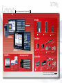
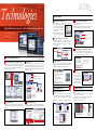
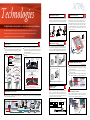
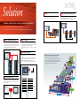
MITSUBISHI CNC
M700V Series
The Best Partner for Your Success
Mitsubishi CNC M700V Series
The best machines for top level manufacturing
The one and only. Only top level manufacturing can sur vive.
Mitsubishi CNC M700V Series is a state-of-the-art model that provides high-speed and high-accuracy
machining and advanced control technologies. These Functions are for customers who keep challenging
for more production output, with a worldwide recognized machine for today’s globalized industr y.
M700VS Series is an integrated control unit and display type.
M700V W Series also comes with Windows ®XPe.
These two types of Mitsubishi CNC M700V Series support top level manufacturing.
[Complete NANO]
[5-axis, multi-axis]
Controls everything from the CNC’s operation
to servo processing with a least command
increment of 1nm
Controlling multiple axes allows the
positioning of the tool center point
[High-speed, high-accuracy]
[Easy operation]
High-quality machining by determining
appropriate shapes and avoiding
unnecessary deceleration
Simple programming system
for machining center and lathe
[High-speed, high-accuracy]
[Customize]
High-speed and high-accuracy control of
the drive system is achieved by estimating
program paths from beginning to end
Tools used in developing solutions
for control customization
M700series
V
MITSUBISHI CNC
The Best Partner for Your Success
M700VS and M700VW Series, advanced Mitsubishi CNCs for next-generation machining
1
2
M700series
V
System Configurations & Product Lines
Drive Unit
Mitsubishi CNC
M700VW Series
M700VS Series
Multi-hybrid drive unit
MDS-DM2 Series
M700VWSeries
High-performance drive unit
MDS-D2/DH2 Series
Ultra-compact drive unit with
built-in power supply
MDS-DJ Series
Servo Motor
Linear servo motor
LM-F Series
M700VSSeries
MELSOFT
Medium-inertia motor
HF Series
Machine Operation Panel
(Tools)
Low-inertia motor
HF-KP Series
Direct drive servo motor
TM-RB Series
Spindle Motor
Rotary detector
MBA Series
Built-in spindle motor
SJ-BG Series
SJ-B Series
Personal computer+Windows
®
NC Designer
NC Monitor
NC Explorer
NC Trainer
NC Trainer plus
NC Analyzer
NC Configurator2
GX Developer
NC Maintainer
etc.
High-performance
spindle motor
SJ-D Series
SJ-V Series
Low-inertia and high-speed
spindle motor
SJ-DL Series
SJ-VL Series
Tool spindle motor
HF-KP Series
HF-SP Series
Detector for C axis
MBE Series
From drive units to servo/spindle motors
Advanced CNC components for higher performance
3
4
M700series
V
Technologies
Complete Nano Control
PLC Axis
All operations from program values to servo commands are
done in nanometer units. Interpolation is at the nano-unit
level even when program commands are in micrometer
units.
Basic Performance and Functions
High-speed architecture
Indexing function
By setting the number of stations required for the application,
the drive automatically sets up equal intervals between each
station. Positioning of the axis is only possible by
commanding the station number.
Drive unit
MDS-D2/DH2
M700V Series
For higher speed and higher accuracy
1
24
Table
23
22
High-gain control II
High-accuracy detector:
16million p/rev
21
9
Speed command fluctuation reduced
In complete nano control, the position command calculation
fraction of the interpolation calculation is small, so fluctuations in speed command due to the fractions is reduced.
This reduces acceleration fluctuations, resulting in finer lines
at the time of repeated acceleration/deceleration.
Micron system (Our conventional)
Complete nano system (M700V Series)
Speed
Speed
Machining Program Processing Speed
Decelerator
11
M700V Series
13
14
18
17
16
15
Indexing function with magazine axis
PLC axis mixed control
Even if a pallet is changed, the axis can always be controlled
as an NC axis in the machining area, and as a PLC axis in
the setup area, which enables setup of a rotary axis without
stopping machining.
Speed fluctuation
Acceleration
rate
135kBPM(Note 1)
168kBPM
12
Servo motor
19
Setup area
(Note 2)
5
6
20
Speed fluctuation
M700 Series
4
7
8
10
Mitsubishi Electric Factory Automation technologies are condensed into a 64 bit RISC
processor and an exclusively developed high speed LSI.
The basic CNC functions, built-in PLC and graphic performance are all improved.
The M700VS has been downsized with power consumption reduced by 66% compared to our
conventional Windows-based control models while maintaining the same performance.
Windows®XPe-based M700VW was designed with expandability and stability to
enable a higher level of custom functions.
3
Indexing position
High-speed
optical network
Bringing the complete nano world closer to you
2
Z
(Note 1) BPM is the number of machining program blocks processed per minute.
(Note 2) M720VS’s machining program processing speed is 67.5kBPM.
User Macro Processing Performance
A’
Y
X
Controlled as a PLC axis
independent from an NC
axis
Interpolation calculation accuracy improved
Even with one-micron-unit commands in the machining program, interpolation is in nanometer units. As the calculation
accuracy of a block intersection is improved, lines on the
surface is finer.
(Note 1)
Machining area
Acceleration
rate
Controlled
as NC axis
A
C
1
M700 Series
Y [mm]
Example of PLC axis mixed control with a pallet changer
7.795000
M700V Series
Nano system
(M700V Series)
7.794784
2
Theoretical value
Micron system
7.794000
Built-in PLC Basic Instruction Processing Performance
M700 Series
M700V Series
X [mm]
4.457000
10 steps/µs
Y [mm]
100 steps/µs
4.458000
4.457693
Theoretical value
Index Modification Function of
PLC Instructions
The index modification function is available, which is one of
MELSEC’s wide variety of instructions.
Repetitive programs can be written easily.
When several similar programs exist...
6
X0
3
“n” number of same programs can be
written in one line
X1
PLS M0
M0
3
6
9
SM400
Y8
X [mm]
XA
MOV KO ZO
FOR K171
XB
PLS M10
X0Z0
M10
XAA
SM400
XAB
PLS M170
INC Z0
YB2
NEXT
M170
5
X1Z0
Y8Z0
Y12
6
M700series
V
Technologies
Position-dependent Gradually
Increasing-type Backlash Compensation
Protrusion is reduced by gradually changing the backlash
compensation amount according to the reversal of axis
travel direction, which enables higher-accuracy machining.
+Y
Two-way Pitch Error Compensation
The pitch error compensation function has been improved.
By setting the compensation amounts separately for the
positive and negative directions, different compensation can
be applied to each direction.
S u p p o r t i n g M a c h i n e To o l A c c u r a c y I m p r o v e m e n t
Actual machine position
+X
-X
Calculated control (OMR control) of the drive system based on the machine model realizes
Pitch error compensation amounts
are different in the positive and
negative directions
optimum machine operation
Actual machine
position without
the positive
direction
compensation
Ideal machine
position
Actual machine
position without
the negative direction
compensation
-Y
Pitch error compensation amount
in positive direction
Commanded
machine position
Pitch error compensation amount
in negative direction
Adaptive Notch Filter
A high-speed error-compensation function is used for controlling the spindle and servo, enabling accurate tapping.
Servo drive unit
Spindle drive unit
Protrusion occurs due
to backlash compensation
This function is used to estimate the resonance frequency of
the machine and automatically adjust notch filter parameters.
This enables the system to monitor the machine fluctuations
and prevents repeated fluctuations caused by aged deterioration.
Table
MDS-D2/DH2 servo drive unit
Servo
motor
Directly compensates
synchronization error
Position
control
Speed
control
Resonance
control
Linear
scale
Current
control
Spindle motor
Servo motor
M700V Series
4000
3000
2000
1000
0
−1000
4000
3000
2000
1000
0
−1000
Spindle speed
Servo/spindle
synchronization
error
−2000
−3000
−4000
0
0.5
Resonance 1
Spindle speed
(r/min)
Spindle speed
(r/min)
1
1.5
Fine-tune the filters'
frequencies within a
certain band to
respond to the
resonance frequency
changes
Spindle speed
2
2.5
3
3.5
0
0.5
1
1.5
Notch filter 1
High traceability to command (High-gain control II), which
has been developed in servo axis control, is now available on
spindles, contributes to shorter machining time and higher
accuracy.
Spindle/C-axis control
The spindle's constant position loop control has eliminated
the zero point return time when switching from the spindle to
C-axis.
Speed
Notch filter 3
Reduced harmonic current mitigates heat generation in the
spindle motor.
2
2.5
3
Zero
point return
3.5
(Sec.)
Corresponds to machine resonance fluctuations
By compensating for the deflection between the motor-end
and machine-end, the part shape at a high speed and
acceleration rate can be compensated for. The optimal shape
can be obtained at a low feed rate and also compensate for
the outward expansion of the shape at high feed rates.
Command path
Lost Motion Compensation Control Type 3
This control can compensate for not only the machine friction
but also the spring and viscosity elements. Thus quadrant
protrusions, which are generated in circular cutting, can be
compensated for within a wide range from low-speed to
high-speed cutting.
C-axis
positioning
2. Difference between static and dynamic
friction is large and steep
<MDS-D2/DH2 Series>
Speed
1
At a low
feed rate
At a high
feed rate
7
Time
0.8
Time
<MDS-D2/DH2 Series>
At a high
feed rate
At a low
feed rate
At a high feed rate, the optimal shape is
expanded due to the deflection between
the motor-end and machine-end.
Without compensation
<Our conventional series>
The commanded path is compensating for the
deflection of error, which provides the ability to
produce a correct shape at high feed rates.
With compensation
+X
+X
3µm
3µm
Conventional compensation control
Lost motion compensation control type 3
Temperature
rise cut by 10%
Combined with MDS-D2 Series
20
0
0
20
40
60
Time [s]
80
100
120
<Condition> Rotation speed: 1200r/min
MDS-D2 spindle drive
Temperature
compensation control
NC
Spindle motor
Spindle motor
temperature
data
Optimal current
control
Built-in thermistor
Reduced by 20%
Not only friction but also spring and
viscosity elements can be compensated
for, thus quadrant protrusions are
suppressed within a wide band
+Y
40
Spindle motor
temperature monitor
Conventional compensation is not enough
+Y
60
Time
Orientation time is reduced
Deceleration is performed with the maximum torque to minimize the spindle orientation time.
Speed
1. Mechanical spring element can
influence the path
75.9 deg
67.4 deg
Combined with our
conventional series
A built-in thermistor detects the spindle motor's temperature
to compensate for the acceleration/deceleration time when
the motor is at a low temperature. It is also possible to
monitor the spindle motor's temperature on the NC screen.
C-axis
positioning
<Our conventional series> Time
Spindle motor temperature rise characteristics
80
Automatic Temperature Compensation of
Spindle Motor
Speed
Zero point return is
not necessary.
Shortened
With OMR-DD control
(M700V Series)
The commanded
program path is
compensated
inwards at a high
feed rate.
Notch filter 2
Lowering Heat Generation of Spindle Motors
Position Loop of Spindle Control
Resonance frequency
estimating parts
Machine-end Compensation Control
Command path
Resonance 3
Frequency
Servo/spindle
−2000
synchronization
−3000 error
−4000
Without OMR-DD control (Sec.)
Resonance 2
Optimum backlash compensation
reduces the protrusion
Heavy cutting performance improved
Heavy cutting performance has been improved with the addition of position loop control on the spindle. By lowering the
impact load fluctuation, the speed fluctuation rate has been
reduced to less than 1/2 of our conventional system.
Spindle acceleration/
deceleration time
shortened
The change of accel/decel
characteristics due to
motor temperature
changes can be
suppressed, which allows
the system to be
controlled at a constant
accel/decel rate.
Without compensation
[Acceleration]
Without compensation
[Deceleration]
S12000 Acceleration/deceleration time [s]
Optimum Machine Response Direct Drive
Temperature rise [deg]
OMR-DD Control (High-speed synchronous tapping)
: Compensation division point
With compensation
[Acceleration]
With compensation
[Deceleration]
2.50
2.40
Effect of suppressing
acceleration/deceleration
time fluctuation
2.30
2.20
2.10
2.00
1.90
1.80
1.70
1.60
1.50
20
40
60
80
100
Stator (thermistor) temperature [°C]
8
M700series
V
Technologies
Operation Support
Program input error warning function
Manual/Automatic backup function
Human Machine Interface provides for better visibility and operator ease of use
Easy-to-use interface with
useful functions
Batch-backup of the NC data into the memory card/USB
memory inserted in the front interface of the display is possible. For
the built-in hard disk type M700VW
Series, backup in the hard disk is
also possible.
Data is automatically backed-up at
a certain interval set by the pa- Manual/automatic backup function
rameter.
The added 3D solid model check function allows more realistic cutting check.*
This function helps an operator to input and check programs.
Errors are indicated when a decimal point is omitted.
Integration of program check
and editing functions
Decimal point omitted: A decimal
point has been left out of the
address data
Operability of operation search improved
Using the program edit screen, it is possible to execute a
program from the line specified by the cursor. The operation
search immediately detects the edited part to check the
content of operation.
Move the cursor
to the line to start
execution
Execution starts
from the specified
line
INPUT
HMI for Easier and More Visible Use
Screen structure linking to the operation processes
Operation processes are divided into three steps, “Monitor”,
“Setup” and “Edit”, and necessary information is aggregated
into three screens. These screens can be displayed by touching a single button on the keyboard.
Pop-up screens
Tabs allow the user to select necessary operations from the
operation menu, and pop-up screens allow the user to
access desired information while the original screen remains
displayed. For displays with a touch panel, a keyboard can be
displayed on the screen.
The program can be restarted
using only the INPUT operation
Guidance function
By pressing the help button, guidance (operation procedure
/parameter descriptions/alarm descriptions/G code format) regarding the currently displayed screen will be shown.
Menu list
Menu list buttons are
newly introduced. With
these buttons, the screen
desired for display can be
called up directly. The selected screen’s function
outline is also displayed.
Large amount of information aggregated
into one screen
Machining conditions are displayed visually
Icon menu displays
screen images
NAVI MILL (for machining center)/
NAVI LATHE (for lathe)
Counter display is
automatically enlarged
in the manual mode
Pop-up window
to avoid screen
switching
Visible hierarchy
with 2-layer menu
display
Keyboard is displayed
in the pop-up window
(for touch-panel displays)
Monitor screen
Setup screen
2-part system display
The Monitor screen of the 2nd part system can be displayed
together with the 1st part system. Switching screens is not
necessary.
Operability of program restart function improved
Even if a machining program is stopped for reasons such as
tool breakage, the program can be restarted when it has
been stopped using only the INPUT operation.
(HMI:Human Machine Interface)
Tab selection
Edit screen
Program check based on a 3D solid model
*Available with M700V Series (M System) only.
Simple programming function
Programs are automatically created for each process when
an operator selects machining process and inputs data on
screen. A tool path can be graphically drawn for the program
check.
This function also supports in-clined surface machining.
Shortcut icons to each screen
Outline of the
selected function
appears
Program Operation
Machining programs in the memory card or in the hard
disk (for M700VW Series) can be directly searched and
run. Direct edit is also available.
Sub-program call is available from machining programs
stored in the memory card or hard disk.
The program format is unlimited.
Menu customization function
Menu keys on the bottom of the screen can be freely arranged.
Frequently used menu keys can be put together on the first page.
Insert
CF/PCMCIA card
fully inserted
NAVI MILL (Machining center system)
NAVI LATHE (Lathe system)
M700V Series
Guide image area
An operator sets the
shape of the inclined
surface to machine
CF card
The M700VW Series is equipped with a PCMCIA II slot
A CF card can be also used with an adapter
In the case of the M700VW
Series, a CF card can be
installed in the control unit
Machining
surface view
2-part system display
9
10
M700series
V
Technologies
Inclined Surface Machining
Tool Center Point Control
(Machining Center System)
(Machining Center System)
*M750VS, M750VW only
High-accuracy machining is realized by controlling each axis
so that the tool center point moves linearly at a commanded
feed rate even if the rotary axis moves in linear interpolation.
For High Quality machining with smoother finish and faster performance
Five-Axis Machining functions such as Tool Center Point and SSS control have been enhanced.
<Tool tilt type>
Rotation center
With the enhancement of these functions, five-axis control will provide high-end performance.
<Table tilt type>
<Compound type>
Path of the
tool center
point
Path of the
tool center
point
You can rotate or move the origin of the original coordinate
system parallel to define a feature coordinate system. To
start machining, issue normal program commands to the arbitrary plane (inclined surface) in space. The feature coordinate system is set again according to the tool axis’s direction. The machining program can be created without paying
attention to the direction of the coordinate system or tool
axis rotational direction.
Rotation center
The advanced five-axis control provides great potentialities.
Rotation center
Path of the tool center point
Feature coordinate
system
Tool Handle Feed & Interruption
(Machining Center System)
SSS Control (Machining Center System)
*M730VS,M730VW,M750VS,M750VW only
Super Smooth Surface
By judging part program paths, unnecessary deceleration
is reduced, even when fine steps in the program exist. This
provides a smooth finish without deviation for die-mold machining.
Surface accuracy
Surface accuracy improved
in the same machining time.
(2 to 10 times higher than
our conventional system)
SSS control
High
This function suppresses the vibrations of the tool by
moving the rotary axis smoothly. Even when this function is
active, the Tool Center Point path moves according to the
command program path.
SSS control can be used during simultaneous five-axis
machining.
Without rotary axis pre-filter
Travel with no change
in tool’s posture
Machining time shorter
with the same surface accuracy
(5 to 30% faster than
our conventional system)
Conventional
control
Low
High
Path A
Path B
Travel with change
in tool’s posture
(Sudden travel)
Q4
Q3
Q5
Q6
Q7
Q1
Q8
It is possible to move in the tool axis direction in both X & Y radius directions.
P0
P1
P2
P3
P4
P5
P6
P7
P8
P9
Vibration occurs
Travel path of tool center points
at change of tool’s posture
Only during travel with a change in the tool position,
the rotary axis will suddenly move causing vibration at the tool center point.
Tiny difference in level
With rotary axis pre-filter
Rotary axis travel commands are smoothed.
Actual cutting path
Scratches on machined surface
Without SSS control
Q4
Q3
Q2
Q1
Path B
Path B
X axis
Inclined surface machining
*M730VW,M750VW only
Tiny difference in level
Tiny difference in level
Original
coordinate
system
X axis
3D Machine Interference Check
Tool radius
direction X
Smooth command path
Path A
Y axis
Tool axis
direction
Workpiece
Workpiece
Smooth command path
Actual cutting path
Z axis
Y axis
Z axis
Tool radius direction Y
Travel path of machine
rotation centers
Speed
Smooth command path
Path A
Q2
More effective at a higher rate
Low
The Tool Handle Feed & Interruption function enables you to
perform handle feed by making the tool diameter direction as an
X or Y axis of complicated workpiece under five-axis machining.
The tool position can be changed without moving the tool tip.
This function prevents interference on a machine model (in
both manual and automatic operations) before it actually
happens in the machine.
The part to interfere can be checked by moving, rotating or
en-larging the models.
Interference can be prevented for a tilt-type tool axis and rotating
table. (Useful when soft limit is not enough to prevent interference)
Workpiece
Q5
Q6
Q7
Q8
Interpolation for smooth step cutting
With SSS control
Without moving the tool tip, it is possible to change the tool’s position.
P0
P1
P2
P3
P4
P5
P6
P7
Rotary axis travel command
positions are smoothed
P8
P9
Travel path of tool center points
Tool position changes smoothly,
causing no vibration at the tool center point which allows the tool to move smoothly.
R-Navi (Machining Center System)
Provides easy setup of index machining (multiple/inclined
surface machining) using a rotary axis.
Enables secure, easy and smooth setup and index machining
OMR-FF Control
Machine model
Optimum Feed Forward
Unlike conventional control, which simply matches the motor
path to the commands, OMR control calculates the machine's status based on a model and applies correction to
motor control in order to match not the motor position, but
the machine tool position to the commands.
Check using machine and tool models
Register the model data
Example of detecting a tool interference
while a tilt type tool is rotating
When a possibility of interference is detected on a machine
model, the motor decelerates to a stop before interfering.
The part to interfere is displayed in a different color.
A sign displayed during selection
Manual
Three-axis
machining
program
Inclined
coordinate
system
Register
11
Motor-end
Motor
Machine-end
Machine
Motor
Ball screw
Register machining
surface
Select machining surface
Index machining surface
Three-axis machining
Machining
Machining
result
Calculation
OMR-FF Control
Select a machining surface by
specifying the figure or name
* Some functions are under development.
Current
Servo
Select
Automatic
Visually check the
registered surface
Command
NC
Table
Guide
Motor decelerates to a stop
before interfering.
The part to interfere
changes in color.
12
M700series
V
Technologies
2-part System Synchronous Thread Cutting
Milling Interpolation (Lathe System)
Va r i o u s F u n c t i o n s f o r C o m p o u n d M a c h i n i n g
(Lathe System)
This function converts the commands programmed for the
orthogonal coordinate axes into linear axis movements (tool
movements) and rotary axis movements (workpiece rotation)
to control the contours. This enables milling operations using
a lathe without a Y axis.
G16 (Y-Z cylindrical plane)
X
Supports various compound machining applications, from multi-part system program paths for
X
C
multi-axis machining centers to multi-axis milling and hobbing.
Z
Z
2-part system synchronous thread cutting allows the 1st
part system and the 2nd part system to perform thread cutting simultaneously for the same spindle.
2-part system synchronous thread cutting has two commands; command (G76.1) for cutting threads in two places
simultaneously, which is known as “2-part system
synchronous thread cutting cycle I”; and command (G76.2)
for cutting a thread using the two part systems simultaneously, which is known as “2-part system synchronous
thread cutting cycle II”.
Y
G19 (Y-Z plane)
X
Hypothetical
axis
Multi-part Systems Multi-axis
Machining Center
Y
PLC4
PLC5
B
Z
C
PLC1
PLC3
Separate programs, used in each part system, can be managed under a common name in the multi-part system. This
function facilitates management of the process programs
that are simultaneously executed in the multi-part systems.
Machining programs
X
2nd
1st
part system part system
n-th
part system
100.PRG
100.PRG
100.PRG
200.PRG
200.PRG
200.PRG
300.PRG
300.PRG
300.PRG
X3
X1
X2
Z2
SP1
Deflection can be minimized by holding tools simultaneously
from both sides of the workpiece and using them in synchronization to machine the workpiece (balance cutting).
The machining time can be reduced by machining with two
tools.
(1st part system)
The same program Nos.
can be managed in batch
across part systems
Guide Bushing Spindle Synchronization Control
(Lathe System)
This function is for a machine with a spindle motor to rotate a
guide bushing: This function allows the guide bushing spindle motor (G/B spindle) to synchronize with a reference spindle motor (Reference spindle).
The position error compensation function reduces the
spindle’s vibration due to the workpiece’s torsion, and the
motor’s overload.
1st
2nd
part system part system
n-th
part system
Bar feeder
Programs are managed
separately for each part system.
SP4
Bar feeder
(2nd part system)
SP2
Control Axis Superimposition (Lathe System)
Control Axis Synchronization Across
Part Systems (Lathe System)
Synchronization control enables an arbitrary control axis in
the other part system to move in synchronization with the
movement command assigned to an arbitrary control axis.
This function enables machining using a certain part system
simultaneously with that of another part system by superimposing
their movements.
This is effective when machining in multiple part systems is executed simultaneously. It allows for an axis to shift its coordinate system relative to the system using the axis.
Collet chuck
Guide bushing
(Reference spindle)
(G/B spindle)
Hobbing (Lathe System)
G code format is available for hobbing.
A spur gear can be machined by synchronously rotating the
hob axis and the workpiece axis in a constant ratio. A helical gear can be machined by compensating the workpiece
axis according to the gear torsion angle for the Z axis
movement.
X1
X1
2-part system synchronous
thread cutting cycle II
MDI
X4
Z1
SP3
2-part system synchronous
thread cutting cycle I
Balance Cut (Lathe System)
Programs are managed
separately for each part system.
Each part system can have its
own program Nos.
PLC2
Compound Lathe
Z
Y
Multi-part System Program Management
A maximum of two part systems and 16 axes can be
controlled for the machining center. A maximum of four part
systems and 16 axes can be controlled for the lathe.
(A maximum of two part systems and 12 axes for M720VS,
M720VW)
S
Milling interpolation plane
(G17plane)
Mixed Control (cross axis control)
(Lathe System)
The control axes of each part system can be exchanged
using a program command. This enables the axis defined as
the axis of the 1st part system to be operated as the axis of
the 2nd part system.
Workpiece travel command
for the 1st part system
Z2
<Synchronized axis>
Switching C1 axis control from the 1st part system to the 2nd part system
Hob axis
Z1
1st part system
1st part system
X1
Z1
X1
Z1
Tool travel
command
for the 2nd
part system
Z1
<Base axis>
13
C1
C1
Z2
X2
Workpiece axis
The tool moves so as to keep
its relative position with the workpiece
Z2
X2
2nd part system
Z2
X2
2nd part system
14
M700series
V
Solution
NC Analyzer
(Servo Adjustment Support Tool)
Servo Selection Tool
By selecting the machine configuration model and inputting the
machine specifications, the optimal servo motor meeting specifications can be selected. Other selection functions which fully
support drive system selection are also available. This tool is
free of charge. Please contact us.
C u s t o m i z a t i o n / S u p p o r t To o l
<Main functions>
Servo motor capacity selection, regenerative resistor capacity selection,
spindle acceleration/deceleration time calculation, power supply capacity
selection, power supply facility capacity calculation, etc.
NC Designer and other Software Applications tools are available to support the customization
Servo parameters can be automatically adjusted by activating the motor using machining programs for adjustment or
vibration signals, and measuring/analyzing the machine characteristics.
<Main functions>
Bode diagram measurement display, speed loop gain adjustment, position loop gain adjustment, notch filter setting, acceleration/deceleration
time constant adjustment, circularity adjustment and servo waveform
measurement.
of the machine. Some software applications support a C Language Library to support a higher
level of customization.
Ethernet
communication
NC Designer (Screen Design Tool)
By laying out ready-made standard parts, you can easily
create original screens without programming.
When using touch panel display, a machine operation
panel can be built on the NC display.
Events of the standard parts can be described using
macros.
Using the C language source generation function of NC
Designer, customized functions can be added by programming in C language. (Dedicated development environment
necessary.)
Simply by locating parts of various functions on the screen,
it is possible to create custom screens easily.
It is possible to check the performance of custom screens
on a personal computer.
Develop screen configuration
When the machine model and input specifications are selected,
the selection result for the motor will be displayed.
The result can be output in PDF format.
NC Configurator2
(Parameter Setup Support Tool)
The NC data file necessary for NC control and machine operation (such as parameters, tool data and common variables)
can be edited on a personal computer.
Please contact us to purchase a full function version. (A limited
function version is also available free of charge.)
Control
Parts displayed
NC Analyzer
M700V Series
NC Monitor (Remote Monitoring Tool)
An identical NC display screen can be displayed on a personal computer. By connecting a personal computer to the
NC unit when necessary, various data can be checked and
set using the same HMI as the standard NC screen.
Edit on a personal computer
Graphic Window
Memory card
M700VW Series
NC Configurator2
M700VS Series
NC Designer
GX Developer (Sequence Programming Tool)
M700V Series
NC Trainer / NC Trainer plus
(MITSUBISHI CNC Training Tool)
NC Maintainer
*M700VW only
The MELSEC programming tool, offering a wide array of
functions and easy use, allows for convenient program
design and debugging. Linking with a simulator or other utility allows for the efficient creation of desired programs.
Ethernet
communication
Ethernet
communication
Parts displayed on NC
(example)
A software tool for a personal computer to carry out maintenance (such as parameter setting, NC diagnosis and PLC program diagnosis) of MITSUBISHI CNC on customer’s display.
NC Trainer is an application for operating the screens of
MITSUBISHI CNC M700V Series and machining programs.
This application can be used for learning operating CNC
and checking the operations of the machining programs.
NC Trainer plus can also be used for checking the PLC
program and custom screens.
NC Monitor
NC Explorer (Data Transfer Tool)
By connecting the NC and host personal computer via
Ethernet, data such as machining programs can easily be
shared. This tool is free of charge. Please contact us.
NC1
Ethernet
communication
Ethernet
Customer’s display
communication
Control unit
NC2
NC3
NC5
NC6
Ethernet
Memory card
USB memory
GX Developer
M700V Series
NC4
M700V Series
Machining program
Diagnosis screen
Maintenance screen
PLC program diagnosis screen
NC Trainer
NC Trainer plus
NC Explorer
(Note) An operation check is required in combination with software installed on the display.
15
16
M700series
V
Solution
CC-Link
Optical Communication Repeater Unit
The NC unit can be connected to a network to serve as the
master/local station of the MELSEC CC-Link.
The optical cable can be extended to a maximum of 90m by
connecting up to two optical servo communication repeater
units between the CNC unit and a servo drive unit.
A wide range of support features according to various machine configurations
Easy to import external data via USB and memory card interfaces.
A wide array of network functions offers good compatibility with various machine configurations.
Max. 30m
Memory Card/USB Memory Interface
A compact flash memory card (CF card) (Note) /USB memory
interface is located on the front of the display. In using CF
card, the card slot can be completely covered by a lid so as
to prevent foreign materials from entering (IP67).
(Note) M700VW Series is equipped with PCMCIA interface
Max. 30m
Max. 30m
Optical communication repeater units (Max. 2)
Front IC Card Mode
•It is possible to directly search and run the machining
programs from the CF card (or PCMCIA card for M700VW
Series). Subprogram calls are also available.
•The machining programs in the CF card can be edited
directly.
Example of M700VS Series
Easy to Change Languages
•Display languages can be switched with a single parameter
operation.
•For guidance display, two other languages aside from
English are selectable for M700VS Series, or all the desired
languages for M700VW Series by option setting.
•Support for 17 languages, securing reliable use worldwide.
Mitsubishi Factory Automation Solutions
Production management
Facility maintenance
Quality control
● Our cultivated Factory Automation technologies and
experience contribute to offer the best suited systems for users.
Machining network system
● Our FA solutions support high and low hierarchy components,
a network and even applications that control the components
and network required for a manufacturing floor.
CAD/CAM system
Production management system
Information
technologies
Optimized
Waste eliminated
MELQIC
inspection unit
GOT1000
MES
interface
Mechatronics
technologies
CF card
Ethernet Communication
By connecting a personal computer and an CNC via
Ethernet, the machining programs and parameters can be
input and output.
Ethernet
communication
Machining programs
Parameters
Backup data, etc.
17
Electron beam machine
Control
technologies
Laser
EDM
Higher performance
Languages supported
Japanese
Portuguese
English
Hungarian
German
Dutch
Italian
Swedish
French
Turkish
Spanish
Polish
Chinese (traditional)
Russian
Chinese (simplified)
Czech
Korean
Shorter machining time
MITSUBISHI CNC
M700V/M70V
PLC
Motion
controller
MITSUBISHI CNC
E70
Robot
Drive
technologies
Distribution
technologies
Power measuring
Energy measuring
module
module
MDU
Electric type
circuit breaker
indicator
Higher efficiency
Energy saving
AC servo
Inverter
Robot
Mitsubishi FA
product groups
18
M700series
V
WARRANTY
Control Unit
MITSUBISHI CNC Machine Operation Panel
[mm]
Please confirm the following product warranty details before using MITSUBISHI CNC.
140
FCU7-KB028
Lathe system clear keys
260
10.4-type
290
140
FCU7-KB046
clear keys
8.4-type
290
140
10.4-type
220
FCU7-KB044
sheet keys
8.4-type
15-type
10.4-type touch panel
140
140
290
10.4-type
ー
touch panel
140
10.4-type
220
FCU7-KB026
clear keys
290
140
220
FCU7-KB025
Lathe system sheet keys
8.4-type
260
220
Display
Keyboard
FCU7-KB024
sheet keys
[mm]
M700VS Series
Display
10.4-type
Keyboard
ー
touch panel
400
290
10.4-type
230
230
10.4-type
320
220
FCU7-KB048
clear keys
ー
ー
230
220
290
touch panel
220
Whether during or after the term of warranty, we assume no
responsibility for any damages arising from causes for which we
are not responsible, any losses of opportunity and/or profit incurred
by the customer due to a failure of this product, any damages,
secondary damages or compensation for accidents arising under
specific circumstances that either foreseen or unforeseen by
Mitsubishi Electric, any damages to products other than this product,
or compensation for any replacement work, readjustment and startup
test run of on-site machines or any other operations conducted by
the customer.
FCU7-KB926
Rotary switches
(spindle override, cutting override)
Select switch
(memory protection)
Emergency stop push-button
D i s p l ays & Key b o a r d
200
3. Exclusion of Responsibility for Compensation against Loss of Opportunity, Secondary Loss, etc.
Key switch 55 points, LED 55 points
MITSUBISHI standard key layout
-The internal components of the machine operation panel are protected
against water and oil (IP65F).
-Refer to the product brochure for details.
control unit
200
If the customer installs the product purchased from us in his/her
machine or equipment, and export it to any country other than where
he/she bought it, the customer may sign a paid warranty contract
with our local FA center.
This falls under the case where the product purchased from us in or
outside Japan is exported and installed in any country other than
where it was purchased.
For details please contact the distributor from which the customer
purchased the product.
FCU7-KB921
15-type
400
290
4. Changes in Product Specifications
10.4-type
FCU7-KB047
clear keys
10.4-type
320
220
160
touch panel
5. Product Application
290
M700VW Series
10.4-type
FCU7-KB041
clear keys
290
230
220
290
10.4-type
15-type
10.4-type touch panel
400
230
10.4-type
touch panel
15-type touch panel
230
400
15-type
320
Display
320
Keyboard
230
15-type
touch panel
400
290
15-type
touch panel
160
320
15-type
160
10.4-type
touch panel
320
220
10.4-type
400
290
160
FCU7-KB045
clear keys
220
(1) For the use of this product, its applications should be those that
may not result in a serious damage even if any failure or
malfunction occurs in the product, and a backup or fail-safe
function should operate on an external system to the product
when any failure or malfunction occurs.
(2) Mitsubishi CNC is designed and manufactured solely for
applications to machine tools to be used for industrial purposes.
Do not use this product in any applications other than those
specified above, especially those which are substantially
influential on the public interest or which are expected to have
significant influence on human lives or properties.
15-type
160
8.4-type
160
FCU7-KB029
sheet keys
220
200
260
140
Specifications shown in our catalogs, manuals or technical documents
are subject to change without notice.
290
220
[Limitations]
(1) The customer is requested to conduct an initial failure diagnosis
by him/herself, as a general rule. It can also be carried out by us
or our service provider upon the customer’s request and the
actual cost will be charged.
(2) This warranty applies only when the conditions, method,
environment, etc., of use are in compliance with the terms and
conditions and instructions that are set forth in the instruction
manual, user’s manual, and the caution label affixed to the
product, etc.
(3) Even during the term of warranty, repair costs shall be charged to
the customer in the following cases:
(a) a failure caused by improper storage or handling,
carelessness or negligence, etc., or a failure caused by the
customer’s hardware or software problem
(b) a failure caused by any alteration, etc., to the product made
by the customer without Mitsubishi Electric’s approval
(c) a failure which may be regarded as avoidable, if the
customer’s equipment in which this product is incorporated is
equipped with a safety device required by applicable laws or
has any function or structure considered to be indispensable
in the light of common sense in the industry
(d) a failure which may be regarded as avoidable if consumable
parts designated in the instruction manual, etc. are duly
maintained and replaced
(e) any replacement of consumable parts (including a battery,
relay and fuse)
(f) a failure caused by external factors such as inevitable
accidents, including without limitation fire and abnormal
fluctuation of voltage, and acts of God, including without
limitation earthquake, lightning, and natural disasters
control unit
220
[Warranty Term]
The term of warranty for this product shall be twenty-four (24)
months from the date of delivery of product to the end user, provided
the product purchased from us in Japan is installed in Japan (but in
no event longer than thirty (30) months, Including the distribution
time after shipment from Mitsubishi Electric or its distributor).
Note that, for the case where the product purchased from us in or
outside Japan is exported and installed in any country other than
where it was purchased; please refer to "2. Service in overseas
countries" as will be explained.
2. Service in Overseas Countries
160
Should any fault or defect (hereafter called "failure") for which we
are liable occur in this product during the warranty period, we shall
provide repair services at no cost through the distributor from which
the product was purchased or through a Mitsubishi Electric service
provider. Note, however that this shall not apply if the customer was
informed prior to purchase of the product that the product is not
covered under warranty. Also note that we are not responsible for
any on-site readjustment and/or trial run that may be required after
a defective unit is replaced.
Fully
compatible with
conventional
M700 Series
Integrated
on the back
of display
220
1. Warranty Period and Coverage
M700VW Series control unit
CNC unit is separated from
the operation board.
140
M700VS Series control unit
(g) a failure which is unforeseeable under technologies available
at the time of shipment of this product from our company
(h) any other failures which we are not responsible for or which
the customer acknowledges we are not responsible for
140
260
290
290
The internal components of the keyboard are protected against water and oil (IP65F). The interface for USB memory and CF card (PCMCIA II for M700VW Series) are mounted on the front panel of the display.
* Trademarks
MELDAS, MELSEC, EZSocket, EZMotion, iQ Platform, MELSOFT, GOT, CC-Link, CC-Link/LT and CC-Link IE are either trademarks or registered trademarks
of Mitsubishi Electric Corporation in Japan and/or other countries.
Ethernet is a registered trademark of Xerox Corporation in the United States and/or other countries.
Microsoft® and Windows® are either trademarks or registered trademarks of Microsoft Corporation in the United States and/or other countries.
CompactFlash and CF are either trademarks or registered trademarks of SanDisk Corporation in the United States and/or other countries.
Other company and product names that appear in this manual are trademarks or registered trademarks of the respective companies.
19
20
M700series
V
S e r vo M oto r s
Medium-inertia Motor HF Series
Medium-inertia, high-accuracy and high-speed
motors
High-inertia machine accuracy is ensured. Suitable for machines requiring quick acceleration.
Range: 0.5 to 9 [kW]
Maximum speed: 4,000 or 5,000 [r/min]
Supports three types of detectors with a resolution of 260,000, 1 million or 16 million p/rev.
Linear Servo Motor LM-F Series
Use in clean environments is possible since no ball screws are
used and therefore contamination from grease is not an issue.
Elimination of transmission mechanisms which include backlash,
enables smooth and quiet operation even at high speeds.
Dimensions:
Length: 290 to 1,010 [mm]
Width: 120 to 240 [mm]
D r i ve U n i t s
Low-inertia Motor HF-KP Series
Small-capacity, low-inertia motors
Suitable for an auxiliary axis that require
high-speed positioning
Range: 0.1 to 0.75[kW]
Maximum speed: 6,000 [r/min]
Supports a detector with a resolution of 260,000p/rev.
Direct Drive Servo Motor TM-RB Series
High-torque direct-drive combined motor with a
high-gain control system provides quick acceleration
and positioning, which makes rotation smoother.
Suitable for a rotary axis that drives a table or
spindle head.
Compared with a conventional rotary axis with a deceleration gear, this motor has higher accuracy and
is maintenance-free, having no wear or backlash.
Range:
Maximum torque: 36 to 1,280 [N·m]
High-performance Servo/Spindle Drive Units
MDS-D2/DH2 Series
Multi-hybrid Drive Units
MDS-DM2 Series
With the fastest current control cycle, basic performance is drastically enhanced
(high-gain control). A combination of high-speed servo motor and highaccuracy detector helps enhance overall drive performance.
High-speed optical communication enables a shorter position interpolation cycle
and direct communication between drives, promoting further high-speed and
high-accuracy machining.
A high-efficiency fin and low-loss power module have enabled unit downsizing. A
line of drive units driving a maximum of two spindles is available, contributing to a
reduction in control panel size.
STO (safe torque off) is now available.(Note)
A line of high-performance multi-hybrid drive
units are available. The multi-hybrid drive unit
drives a maximum of three servo axes and one
spindle, supporting the ownsizing of units and
offering technical advantages.
A power regeneration system that efficiently
uses energy during deceleration as power
contributes to highly-frequent acceleration/
deceleration and energy savings.
STO (safe torque off) is now available.(Note)
All-in-one compact drive units MDS-DJ Series
Ultra-compact drive units with built-in power supplies contribute to reducing control panel size. The 2-axis type is added for further downsizing.
High-speed optical communication enables a shorter position interpolation cycle
and direct communication between drives, promoting further high-speed and
high-accuracy machining.
A high-efficiency fin and low-loss power module have enabled unit downsizing,
which also leads to a reduction in control panel size.
STO (safe torque off) is now available.(Note)
(Note) Please contact us for availability of STO as a whole system.
S p i n dl e M oto r s
Motor energy loss has been significantly reduced
by optimizing the magnetic circuit.
High-speed-specification bearings are equipped
as standard, achieving higher-speed, lower vibration and improved durability.
Product line:
Normal
SJ-D Series
3.7 to 11 [kW]
Compact & light SJ-DJ Series
5.5 to 15 [kW]
Low-inertia, High-speed New Type Spindle Motor SJ-DL Series
Tapping machine-dedicated spindle motors have
joined the new spindle motor line SJ-D Series in an
effort to speed up drilling and tapping.
Our cutting-edge design technologies have brought
forth higher rigidity and lower vibration of motor despite its light weight.
The low-inertia reduces acceleration/deceleration
time, resulting in higher productivity.
Product line:
Low-inertia
SJ-DL Series
0.75 to 7.5 [kW]
Built-in Spindle Motor SJ-BG Series
The optimized electrical design increases
the continuous rated torque per unit
volume compared to our conventional
model, contributing to downsizing of the
spindle unit.
The mold with cooling jacket is available
as an optional feature.
Main Specifications
High-performance Spindle Motor SJ-V Series
A vast range of spindle motors is available, including standard,
high-speed and wide-range output units, all ready to support
diversified machine tool needs.
Product line:
Normal
SJ-V Series
0.75 to 55 [kW]
Wide-range constant output
SJ-V Series
5.5 to 18.5 [kW]
High-speed
SJ-V-Z Series
2.2 to 22 [kW]
Hollow-shaft
SJ-VS Series
5.5 to 18.5 [kW]
Low-inertia, High-speed Spindle Motor SJ-VL Series
The spindle dedicated to tapping machines requiring
faster drilling and tapping.
The low-inertia reduces acceleration/deceleration
time, resulting in higher productivity. In addition,
when driven by a multi-hybrid drive (MDS-DM2
Series), this motor contributes to downsizing of the
cabinet, and energy savings.
Hollow-shaft specifications are also available.
Product line:
Low-inertia normal
SJ-VL Series
3.0 to 11 [kW]
Low-inertia hollow shaft SJ-VLS Series
3.7 to 11 [kW]
Tool Spindle Motor HF-KP/HF-SP Series
Taking advantage of the characteristics of a servo motor such as smallness and
high-output, this motor serves as a compact and high-output spindle motor which
is capable of high-speed rotation (6,000r/min). This
motor contributes to downsizing of spindles, such as the
rotary tool spindle.
Product line:
Small capacity
HF-KP Series 0.4 to 0.9 [kW]
Medium capacity HF-SP Series
2.2 to 4 [kW]
Machining center system
Lathe system
Machining center system
Lathe system
M720VS M730VS M750VS M720VS M730VS M750VS M720VW M730VW M750VW M720VW M730VW M750VW
16
Max. number of axes (NC axes + Spindles + PLC axes)
16
16
16
12
12
12
12
16
Max. number of NC axes (in total for all the part systems)
16
16
16
12
8
8
12
4
Max. number of spindles
6
6
4
4
4
6
6
6
Max. number of PLC axes
6
ー
6
ー
Max. number of auxiliary axes
6
4
4
6
Max. number of PLC indexing axes
6
6
6
4
4
4
4
4
Number of simultaneous contouring control axes
4
4
8
8
8
8
4
8
Max. number of NC axes in a part system
8
8
8
6
6
6
6
2
4
Max. number of part systems
4
2
2
2
ー
Available
ー
CF card in control unit
Available
Available
Available
Available
Front IC card mode
Available
ー
Available
ー
Hard disk mode
Available
1nm
1nm
Least command increment
1nm
1nm
0.1µm
0.1µm
0.1µm
0.1µm
1nm
1nm
1nm
Least control increment
1nm
2,000kB
2,000kB
2,000kB
2,000kB
Max. program capacity
(5,120m)
(5,120m)
(5,120m)
(5,120m)
128,000 steps
128,000 steps
128,000 steps
Max. PLC program capacity
128,000 steps
Milling interpolation
―
―
―
△
△
△
―
―
―
△
△
△
High-speed synchronous tapping(OMR-DD)
○
○
○
○
○
○
○
○
○
○
○
○
Guide bushing spindle synchronization
―
―
―
△
△
△
―
―
―
△
△
△
Tool spindle synchronization II (Hobbing)
―
―
―
△
△
△
―
―
―
△
△
△
Mixed control (cross axis control)
―
―
―
△
△
△
―
―
―
△
△
△
Control axis superimposition
―
―
―
△
△
△
―
―
―
△
△
△
Control axis synchronization across part systems
―
―
―
△
△
△
―
―
―
△
△
△
Balance cut
―
―
―
△
△
△
―
―
―
△
△
△
2-part system synchronous thread cutting
―
―
―
△
△
△
―
―
―
△
△
△
Multi-part system program management
○
○
○
○
○
○
○
○
○
○
○
○
SSS control (Note 1)
△
△
△
―
―
―
△
△
△
―
―
―
3D Machine Interference check
―
―
―
―
―
―
―
△
△
―
―
―
Tool handle feed & interruption
―
△
△
―
―
―
―
△
△
―
―
―
Tool center point control
―
―
△
―
―
―
―
―
△
―
―
―
Inclined surface machining command
△
△
△
―
―
―
△
△
△
―
―
―
R-Navi
△
△
△
―
―
―
△
△
△
―
―
―
Specifications
Number of control axes
High-performance New Type Spindle Motor SJ-D Series
*Maximum specifications including optional specifications are listed.
(Note 1) In order to use this function also in the 2nd part system, the option "High-accuracy control in 2 part systems" is required.
Refer to the specifications manuals.
21
22
BNP-A1210-G[ENG]
M700V Series ( ENGLISH )
BNP-A1210-G[ENG]
(ENGLISH)
K-K02-8-C8220-G NA1312 Printed in Japan (MDOC)
Revised publication, effective Dec. 2013.
Superseding publication of K-K02-8-C8220-F Aug. 2013.
Specifications are subject to change without notice.