1
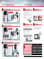
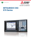
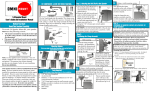
MITSUBISHI CNC
E70 Series
Simple
& Easy
New CNC best suited to
simple lathes/milling machines
New
Seeking easier usability and higher cost efficiency, we have brought out the E70 Series,
a new standard CNC series that succeeds the high performance and high operability of the M70V Series.
While employing the screen configuration of the M700V and M70V Series,
the E70 Series offers even more compact dimensions and less wiring.
With the latest hardware installed, the E70 Series is best suited to simple lathes and milling machines.
High-visibility TFT
color LCD
Lathe system keyboard
now available
Long-life*1, energy saving*2
LED backlight
Simple Operability
High Cost Effectiveness
□Screen design equivalent to M700V/M70V Series, offering
□Very smooth cutting surface achieved with one-nanometer
simple operability.
□Switching between lathe and milling systems is accomplished
simply by changing a parameter.
□Multiple display languages available for global use, which can
be selected by parameter setting.
□A pop-up window shows your desired information without
closing the original window.
position interpolation.*
□Up to 20 sequence programs can be registered with the
built-in PLC function.
□A wide array of development support tools such as NC
Designer is available.
□Ultra-compact drive units with built-in power supplies
contribute to reducing control panel size.
*Least command increment is 0.1µm
Micron system
Nano system (E70 Series)
Speed
fluctuation
High-speed
optical
communication
Speed
Speed
Speed
fluctuation
Manual pulse generator
Acceleration
rate
New MDS-DJ Series
STO (safe torque off) drives available
HF54T-A48
Simple
Induction motor (Note)
(Note) Procured by MTB.
*1 LED backlight life: Approx. 70000 hours (specified value)
*2 Compared with our existing products (energy savings using LED backlight)
1
Compact Size and Less Wiring
MITSUBISHI CNC Machine Operation Panel
□The control unit is integrated into the back side of the display
□The display and keyboard are the same color, providing
to realize compact size.
□Ethernet* is available as standard specification, enabling
input/output of machining programs and parameters by
connecting the NC to a personal computer.
□Front CF card/USB memory interface in the display as
standard specification.
□Analog output offered as standard specification to enable the
use of a spindle drive with an inverter.
Inverter (Note)
MDS-DJ-V2
HF54T-A48
MDS-DM2 Series
Multi-hybrid drive unit
Acceleration
rate
consistency in design.
□The key layout can be customized according to machine
specifications.
□The sequence program samples have been prepared for the
basic key layout.
□Wiring has been reduced by connecting the panel with the NC
via a remote I/O link.
*Refer to the product brochure for details.
MDS-DM2-SPV2-10080
HF104S-A48
HF104S-A48
SJ-DJ5.5/100-01
Example when combined
High-grade
[Examples of connections using E70 Series]
* Ethernet is a registered trademark of Xerox Corporation in the United States and/or other countries.
* CompactFlash and CF are either trademarks or registered trademarks of SanDisk Corporation in the United States and/or other countries.
2
Simple & Easy
Simple & Easy
System Configuration Example
Functions & Usability
Simple, small lathe (with analog spindle)
Inclined Axis Control (lathe system)
Spindle/C-axis Control
Cost effective configuration to control the spindle with an inverter using analog output.
Servo motor(X axis)
HF54S-A48
Number of analog spindles ×1
Number of NC axes
×2(X,Z)
E70(FCA70P-2E)
High-speed optical
communication
Analog output
Servo motor(Z axis)
HF54S-A48
●Even when the control axes configuring a machine are
mounted at an angle other than 90 degrees, this function
enables it to be programmed and controlled in the same way
as with an orthogonal axis.
●The inclination angle is set using a parameter, and axes are
controlled using the movement amounts of the axes which
are obtained through conversion and compensation using
this angle.
<Example of use>
When the X axis serves as the basic
axis and the Y axis serves as the
Yp×tanθ
inclined axis
X: Actual X axis
Y: Actual Y axis
y: Programmed Y axis
θ: Inclination angle
X
Xa
Induction motor
Yp
θ
(procured by MTB)
y
θ
MDS-DJ-V2
Inverter
Yp/cosθ
(procured by MTB)
Ya
Space-saving, cost effective configuration using MDS-DJ Series: Ultra-compact drive unit series with built-in power supply.
Servo motor(X axis)
HF123S-A48
Number of spindles ×1
Number of NC axes ×2(X,Z)
Speed
Speed
Shortened
Zero
point return
C-axis
positioning
<Our conventional series>
C-axis
positioning
Time
<E70 series>
Time
Y
Guidance Function
Simple, small lathe (Drive unit: MDS-DJ Series)
The spindle's constant position loop control has eliminated the
zero point return time when switching from the spindle to
C-axis.
System Lock Function
By pressing the help button, guidance (operation procedure/
parameter descriptions/alarm descriptions/G code format)
regarding the currently displayed screen will be shown.
*Add-on guidance data is required.
This function allows machine tool builders to set the expiration
date for machine use.
If the cancel code is not entered by the specified deadline, the
system forcibly turns OFF the Servo ready completion signal,
placing the machine in an inoperable status.
*We will pay no compensation for any detriment that may arise from an illegal
unlock.
E70(FCA70P-2E)
High-speed optical
communication
Servo motor(Z axis)
HF123S-A48
Operation guidance
Parameter guidance
Alarm guidance
G-code guidance
Spindle motor
SJ-DJ5.5/100-01
MDS-DJ-V1-40
MDS-DJ-V1-40
MDS-DJ-SP-100
Small milling machine (Drive unit: MDS-DM2 Series)
Space-saving, wire-saving configuration to control three servo axes, one spindle and converters with one MDS-DM2 Series drive unit.
Number of spindles ×1
Number of NC axes ×3(X,Y,Z)
Servo motor(Z axis)
HF104BS-A48
Spindle motor
SJ-DJ5.5/100-01
(Z axis is equipped with a brake)
E70(FCA70P-2E)
High-speed optical
communication
Servo motor(X axis)
HF104S-A48
MDS-DM2-SPV3-10080
Servo motor(Y axis)
HF104S-A48
Main Specifications
Model name
Specifications
Maximum number of control axes (NC axes + PLC axes + spindle)
Number Maximum number of NC axes (in total for all the part systems)
of control Maximum number of spindles
Maximum number of PLC axes
axes
Maximum number of simultaneous contour control axes
Maximum number of part systems
Least command increment
Least control increment
Maximum program capacity
Maximum PLC program capacity
Display
Keyboard
HMI customization function
MITSUBISHI CNC machine operation panel
Milling system
6
3
1
2
3
1
Lathe system
6
3
2
2
3
1
0.1µm
1nm
230kB [600m]
8,000 steps
8.4-type
Sheet keys
NC Designer
Compatible
* Maximum specifications including optional specifications are listed.
Refer to the specifications manuals.
3
4
Simple & Easy
Simple & Easy
NC Units & Drive Units
Control Unit, Display & Keyboards
Support Tools
MITSUBISHI CNC Machine Operation Panel
[mm]
FCU7-KB921
8.4-type
FCU7-KB926
Integrated on the
back of display
Rotary switches
(spindle override, cutting override)
Select switch
(memory protection)
Emergency stop push-button
140
NC Analyzer
Screen Design Tool
Servo Adjustment Support Tool
●By laying out ready-made standard parts, you can easily create
original screens without programming.
●Using the C language source generation function of NC
Designer, customized functions can be added by programming
in C language. (Dedicated development environment necessary)
Parts displayed on NC (example)
Servo parameters can be automatically adjusted by activating
the motor using machining programs for adjustment or vibration
signals, and measuring/analyzing the machine characteristics.
<Main functions>
Bode diagram measurement display, speed loop gain adjustment, position loop
gain adjustment, notch filter setting, acceleration/deceleration time constant
adjustment, circularity adjustment and servo waveform measurement
140
FCU7-KB025
Lathe system
sheet keys
Key switch 55 points, LED 55 points
MITSUBISHI standard key layout
140
260
NC Designer
Edit on a personal computer
-The internal components of the machine operation panel are protected against
water and oil (IP65F).
-Refer to the product brochure for details.
Ethernet
communication
Memory card
FCU7-KB024
sheet keys
E70 Series
E70 Series
NC Analyzer
NC Designer
Back of display
NC Monitor
The control unit is integrated into the back side of the display.
NC Configurator2
Remote Monitoring Tool
Drive Units
All-in-one compact drive units MDS-DJ Series
Multi-hybrid Drive Units MDS-DM2 Series
●•Ultra-compact drive units with built-in power supplies
●A line of high-performance multi-hybrid drive units are
contribute to reducing control panel size. The 2-axis type is
added for further downsizing.
●A high-efficiency fin and low-loss power module have
enabled unit downsizing, which also leads to a reduction in
control panel size.
●STO (safe torque off) is now available. (Note)
available. The multi-hybrid drive unit drives a maximum
of three servo axes and one spindle, supporting the
ownsizing of units and offering technical advantages.
●A power regeneration system that efficiently uses
energy during deceleration as power contributes to
highly-frequent acceleration/deceleration and energy
savings.
(Note) Please contact us for availability
●STO (safe torque off) is now available. (Note)
Parameter Setup Support Tool
An identical NC display screen can be displayed on a personal
computer. By connecting a personal computer to the NC unit
when necessary, various data can be checked and set using the
same HMI as the standard NC screen.
Ethernet
communication
Ethernet
communication
NC Monitor
Medium-inertia Motor HF Series
Low-inertia Motor HF-KP Series
●High-inertia machine accuracy is ensured.
●Suitable for an auxiliary axis that require
Suitable for machines requiring quick
acceleration.
●Range: 0.5 to 9 [kW]
●Maximum speed: 4,000 or 5,000 [r/min]
●Supports three types of detectors with a
resolution of 260,000, 1 million or 16 million p/rev.
high-speed positioning
●Range: 0.1 to 0.75 [kW]
●Maximum speed: 6,000 [r/min]
●Supports a detector with a resolution of
260,000p/rev.
NC Configurator2
NC Explorer
NC Trainer/NC Trainer plus
Data Transfer Tool
MITSUBISHI CNC Training Tool
By connecting the NC and host personal computer via Ethernet,
data such as machining programs can easily be shared.
This tool is free of charge. Please contact us.
NC1
Spindle Motors
NC4
Tool Spindle Motor HF-KP Series
●Motor energy loss has been significantly reduced
●Taking advantage of the characteristics of a
servo motor such as smallness and high-output,
this motor serves as a compact and high-output
spindle motor which is capable of high-speed
rotation (6,000r/min). This motor contributes to
downsizing of spindles, such as the rotary tool
spindle.
●Product line:
Small capacity HF-KP Series 0.4 to 0.9 [kW]
NC3
NC5
NC6
Machining program
NC Explorer
5
NC2
●NC Trainer is an application for operating the screens of
M700V/M70V/E70 Series CNCs and machining programs. This
application can be used for learning how to operate CNCs and
checking the operations of machining programs.
●NC Trainer plus can also be used for checking PLC programs
and custom screens.
Ethernet
High-performance New Type Spindle Motor SJ-D Series
by optimizing the magnetic circuit.
●Product line:
Normal
SJ-D Series
3.7 to 11 [kW]
Compact & light SJ-DJ Series
5.5 to 15 [kW]
Low-inertia
SJ-DL Series 0.75∼7.5 [kW]
E70 Series
E70 Series
of STO as a whole system.
Servo Motors
The NC data file necessary for NC control and machine
operation (such as parameters, tool data and common variables)
can be edited on a personal computer.
Please contact us to purchase a full function version. (A limited
function version is also available free of charge.)
NC Trainer
NC Trainer plus
* Ethernet is a registered trademark of Xerox Corporation in the United States and/or other countries.
* CompactFlash and CF are either trademarks or registered trademarks of SanDisk Corporation in the United States and/or other countries.
6
1. Warranty Period and Coverage
Should any fault or defect (hereafter called "failure") for which we are liable occur in this product
during the warranty period, we shall provide repair services at no cost through the distributor from
which the product was purchased or through a Mitsubishi Electric service provider. Note, however that
this shall not apply if the customer was informed prior to purchase of the product that the product is
not covered under warranty. Also note that we are not responsible for any on-site readjustment and/or
trial run that may be required after a defective unit is replaced.
(f) a failure caused by external factors such as inevitable accidents, including without limitation
fire and abnormal fluctuation of voltage, and acts of God, including without limitation
earthquake, lightning, and natural disasters
(g) a failure which is unforeseeable under technologies available at the time of shipment of this
product from our company
(h) any other failures which we are not responsible for or which the customer acknowledges we
are not responsible for
[Warranty Term]
The term of warranty for this product shall be twenty-four (24) months from the date of delivery of
product to the end user, provided the product purchased from us in Japan is installed in Japan (but
in no event longer than thirty (30) months, Including the distribution time after shipment from
Mitsubishi Electric or its distributor).
Note that, for the case where the product purchased from us in or outside Japan is exported and
installed in any country other than where it was purchased; please refer to "2. Service in overseas
countries" as will be explained.
2. Service in Overseas Countries
If the customer installs the product purchased from us in his/her machine or equipment, and export it
to any country other than where he/she bought it, the customer may sign a paid warranty contract with
our local FA center.
This falls under the case where the product purchased from us in or outside Japan is exported and
installed in any country other than where it was purchased.
For details please contact the distributor from which the customer purchased the product.
[Limitations]
(1) The customer is requested to conduct an initial failure diagnosis by him/herself, as a general rule.
It can also be carried out by us or our service provider upon the customer’s request and the actual
cost will be charged.
(2) This warranty applies only when the conditions, method, environment, etc., of use are in
compliance with the terms and conditions and instructions that are set forth in the instruction
manual, user’s manual, and the caution label affixed to the product, etc.
(3) Even during the term of warranty, repair costs shall be charged to the customer in the following
cases:
(a) a failure caused by improper storage or handling, carelessness or negligence, etc., or a failure
caused by the customer’s hardware or software problem
(b) a failure caused by any alteration, etc., to the product made by the customer without Mitsubishi
Electric’s approval
(c) a failure which may be regarded as avoidable, if the customer’s equipment in which this
product is incorporated is equipped with a safety device required by applicable laws or has any
function or structure considered to be indispensable in the light of common sense in the
industry
(d) a failure which may be regarded as avoidable if consumable parts designated in the instruction
manual, etc. are duly maintained and replaced
(e) any replacement of consumable parts (including a battery, relay and fuse)
3. Exclusion of Responsibility for Compensation against Loss of
Opportunity, Secondary Loss, etc.
Whether during or after the term of warranty, we assume no responsibility for any damages arising from
causes for which we are not responsible, any losses of opportunity and/or profit incurred by the customer
due to a failure of this product, any damages, secondary damages or compensation for accidents arising
under specific circumstances that either foreseen or unforeseen by Mitsubishi Electric, any damages to
products other than this product, or compensation for any replacement work, readjustment and startup
test run of on-site machines or any other operations conducted by the customer.
4. Changes in Product Specifications
Specifications shown in our catalogs, manuals or technical documents are subject to change without notice.
5. Product Application
(1) For the use of this product, its applications should be those that may not result in a serious
damage even if any failure or malfunction occurs in the product, and a backup or fail-safe function
should operate on an external system to the product when any failure or malfunction occurs.
(2) Mitsubishi CNC is designed and manufactured solely for applications to machine tools to be used
for industrial purposes.
Do not use this product in any applications other than those specified above, especially those
which are substantially influential on the public interest or which are expected to have significant
influence on human lives or properties.
BNP-A1228-C[ENG]
(ENGLISH)
K-KL2-3-C0101-C NA1312 Printed in Japan (MDOC)
Revised publication, effective Dec. 2013.
Superseding publication of K-KL2-3-C0101-B Aug. 2013.
Specifications are subject to change without notice.
CNC E70 Series ( ENGLISH )
BNP-A1228-C[ENG]
WARRANTY
Please confirm the following product warranty details before using MITSUBISHI CNC.