1
Telepole
Wide Range
Operating & Maintenance Manual
Document # 15-0008
Revision 3
May 2007
The publication, translation or reproduction, either party or wholly, of this document are not allowed without our written consent.
15-0008
Revision 3
May 2007
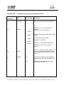
REVISION LOG:
Telepole Wide Range Operating & Maintenance Manual
Date
Revised Pages
Comments
0
6/01/1998
N/A
Original Document number PRIR28T8.DOC
1.0
6/03/99
Revision #
1-4
Updated version, revision log, table of
contents.
Calibration instructions modified.
Chapter 5
Chapter 7
Electronic Block diagrams description chapter
added.
Troubleshooting chapter added.
Chapter 8
Appendix 2 – Calibration.
16,46,47
Appendix 3 – Rotem Meter View Software
48,49,50
Updated title page to reflect all MGPI
manuals.
2.0
2/1/02
3.0
5/1/2007
9
pg 17
Pg 10
Section 3 – clarification of beep pattern for self
test acknowledgement. Clarification of note
pertaining to low range detector connection at
start-up.
Corrected F4 calibration Factor to 200 R/hr
Added wording about optional WRM2 radio
kit
Added comments on optional firmware for
new switching for detectors.
The publication, translation or reproduction, either party or wholly, of this document are not allowed without our written consent.
MGP Instruments reserves the right to change specifications without advance notice
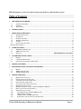
Table of Contents
1.
THE TELEPOLE WR METER................................................................................................................................ 5
1.1.
1.2.
1.3.
GENERAL DESCRIPTION .................................................................................................................................... 5
FEATURES ......................................................................................................................................................... 6
APPLICATIONS ................................................................................................................................................... 6
2.
SPECIFICATIONS .................................................................................................................................................... 7
3.
OPERATING INSTRUCTIONS .............................................................................................................................. 9
3.1.
PREPARATION FOR USE ..................................................................................................................................... 9
3.2.
STARTING-UP .................................................................................................................................................... 9
3.3.
GENERAL FUNCTIONS ....................................................................................................................................... 9
3.4.
THRESHOLD SELECTION .................................................................................................................................. 11
3.5.
ALARMS .......................................................................................................................................................... 12
3.6.
PUSH-BUTTONS FUNCTION .............................................................................................................................. 13
BATTERY REPLACEMENT ................................................................................................................................................ 14
4.
COMMUNICATION ............................................................................................................................................... 14
4.1.
4.2.
4.3.
5.
SMARTS COMMUNICATION ........................................................................................................................... 14
WRM COMMUNICATION ................................................................................................................................. 15
PROTOCOL ................................................................................................ ERROR! BOOKMARK NOT DEFINED.
CALIBRATION INSTRUCTIONS ........................................................................................................................ 17
5.1.
5.2.
5.3.
PREFACE ......................................................................................................................................................... 17
CALIBRATION PROCEDURE .............................................................................................................................. 18
CPU UNIT PULSER CHECK (OPTION ONLY) ................................................................................................... 19
6.
SETTING ID NUMBER .......................................................................................................................................... 21
7.
ELECTRONIC BLOCK DIAGRAMS DESCRIPTION ...................................................................................... 22
7.1.
7.2.
7.3.
8.
METER ............................................................................................................................................................ 22
WRM COMMUNICATION ................................................................................................................................. 28
WIDE RANGE DETECTOR ................................................................................................................................ 28
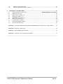
TROUBLESHOOTING........................................................................................................................................... 30
8.1.
8.2.
8.3.
8.4.
8.5.
8.6.
8.7.
8.8.
8.9.
8.10.
8.11.
8.12.
8.13.
METER DOES NOT TURN ON ............................................................................................................................. 30
POWER ON/OFF CIRCUIT (PC 1942) ................................................................................................................. 31
5V POWER SUPPLY CIRCUIT (PC 1495) ............................................................................................................ 32
CPU RESET CIRCUIT (PC 1944) ....................................................................................................................... 33
12V POWER SUPPLY CIRCUIT (PC 1945) .......................................................................................................... 34
METER DOES NOT TURN OFF ............................................................................................................................ 35
METER PARAMETERS ARE NOT SAVED IN THE INTERNAL MEMORY .................................................................. 35
DISPLAY TURNS OFF OR IS INCORRECT............................................................................................................. 36
SPEAKER DOES NOT ALARM............................................................................................................................. 37
NO COMMUNICATION WITH THE WRM SYSTEM .......................................................................................... 38
WRM TRIGGER CHECKING .......................................................................................................................... 39
CHECK TX DATA TO WRM ON PC 1945 ..................................................................................................... 39
INSTRUMENT DOES NOT MEASURE THE RADIATION..................................................................................... 40
TelePole WR/ Operating & Maintenance Manual
Page 3
8.14.
8.15.
9.
DETECTOR FAILURE (PC 2003) ................................................................................................................... 41
ELECTRO LUMINESCENCE DOESN’T TURN ON .............................................................................................. 42
MECHANICAL INSTRUCTIONS ........................................................................................................................ 43
9.1.
9.2.
9.3.
9.4.
9.5.
9.6.
9.7.
9.8.
9.9.
TELESCOPIC POLE CONSTRUCTION ........................................................... ERROR! BOOKMARK NOT DEFINED.
PREPARATION FOR USE ................................................................................................................................... 43
DETECTOR DISASSEMBLY (14) ........................................................................................................................ 48
METER DISASSEMBLY (4, 5) ............................................................................................................................ 48
METER HOLDER ASSEMBLY (4) ...................................................................................................................... 49
DETECTOR ASSEMBLY (14) ............................................................................................................................. 49
POLE SEGMENTS ASSEMBLY ........................................................................................................................... 49
POLE SEGMENTS DISASSEMBLY ...................................................................................................................... 49
TROUBLESHOOTING TABLE ............................................................................................................................. 50
APPENDIX 1 - UPGRADING TELEPOLE INSTRUMENTS FROM HIGH RANGE AND LOW RANGE. TO WIDE. RANGE .......... 45
APPENDIX 2 - TELEPOLE CALIBRATION ..................................................................................................................... 46
APPENDIX 3 - ROTEM METER VIEW SOFTWARE ......................................................................................................... 48
APPENDIX 4 - TELEPOLE - LIST OF ELECTRONIC SCHEMES ........................................................................................ 51
TelePole WR/ Operating & Maintenance Manual
Page 4
1. The TelePole WR Meter
1.1. General Description
The TelePole WR (Wide Range) is a gamma meter, mounted on a telescopic pole, designed
to obtain readings in wide radiation fields. The detector, with its two GM tubes, features a
wide measurement range of 50 µR/h to 1000 R/h (0.5 µSv/h to 10 Sv/h).
The rugged, low maintenance TelePole can be used as a stand-alone instrument or it can be
integrated into systems, using existing equipment and software.
The TelePole’s auto-ranging meter utilizes a combination display consisting of a smoothed
digital readout for minimum fluctuation and a two-decade analog bar graph for fast response.
The four-segment, sturdy, low cost pole extends to eleven feet long and collapses to three and
a half feet for easy transport. The TelePole includes a built-in microprocessor, data memory,
and data downloading capability and optional laser bar-code scanner for use with the survey
mapping software.
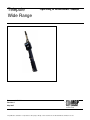
Figure 1-1. TelePole Meter
TelePole WR/ Operating & Maintenance Manual
Page 5
1.2. Features
•
•
•
•
•
•
•
Wide measuring range.
Rugged, sturdy construction combined with low cost replacement parts.
Built-in RJ-11 connection for use with a WRMPlus transmitter.
Optional WRM2 Radio Kit Part Number WR2-A005
Built-in RS-232 communication.
Internal alarm thresholds for exposure rate.
Dual-output “DigiLog” display combines a stable and accurate digital readout with a fast
responding analog bargraph.
• Display backlight offers bright illumination for use in low light areas.
• External DC power supply connection.
• External headphone connection.
1.3. Applications
• Supports ALARA principles by allowing operators to obtain readings at a distance of up to
eleven feet away from the radiation fields.
• Survey instrument, either with simple data storage, or optional bar-code scanner, data
memory and data downloading to survey mapping software.
• Real-time exposure rate monitoring connected to a WRM transmitter. Transmitted data
conforms to existing MGPI monitoring software (i.e. WinWRM2, TeleView 2000).
Note: The dose function of the software displays "888888.88" when transmitting data,
since no accumulated dose function exists on the telepole instrument.
• Areas that are hard-to-reach. (i.e. vehicle surveys, elevated piping, etc.)
TelePole WR/ Operating & Maintenance Manual
Page 6
2. Specifications
Detector
GM tube ZP-1301 (or equivalent) - high range
GM tube ZP-1201 (or equivalent) - low range
Measuring range
0.05 mR/h to 1000 R/h (0.5 µSv/h to 10 Sv/h)
Automatic switching between the two GM tubes at
approximately 800 mR/h and 600 mR/h, optional
firmware to switch 2500 mR/h and 2000 mR/.h.
Accuracy
±10 % of reading, within the measuring range
Energy response (Cs-137)
±20 % at 70 keV to 1.1 MeV
Sensitivity (Cs-137)
Approximately 17 cps/mR/h (low range)
Approximately 0.3 cps/mR/h (high range)
Data logging
380 data records (1550 with extended memory)
Display
DigiLog (3 digits and 2 decades of analog bar graph)
Power source
Two 1.5 Volt C-type alkaline cells,
70 hours of continuous operation
(30% less if back light is kept on continuously)
Temperature range
Operation: -10°C to +50°C (15°F to 122°F)
Storage: -20°C to + 60°C (-5°F to 140°F)
Humidity range
10% to 95% RH (non condensing)
Casing Material
Aluminum, black anodizing
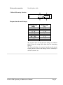
Dimensions
Pole length
Pole length
Width:
93 mm (3.7”)
Length: 148 mm (5.8”)
Height: 56 mm (2.2”)
Length: 226 mm (8.9”)
Diameter: 33 mm (1.3”)
Extended: Up to 337 cm (11 ft)
Collapsed: Down to 107 cm (3.5 ft)
Meter
Probe
Pole
Total
680 gr. (1.5 lbs.)
175 gr. (0.39 lbs.)
1200 gr. (2.7 lbs.)
2055 gr. (7.29 lbs.)
Meter
Probe head
Weight
TelePole WR/ Operating & Maintenance Manual
Page 7
Meter probe connection
Standard phone cable
Calibrate/Measuring direction
ZP-1301
ZP-1201
Response time for small changes
Radiation field
[mR/h]
< 0.6
0.6 - 2.5
2.5 - 20
20 - 60
60 - 400
400 - 2 R/h
2 R/h - 10 R/h
> 10 R/h
Response time
[sec.]
45
20 - 30
5 - 10
2-4
2
2-6
2-3
≤2
The response time for the increased changes in radiation
field is faster for rising filed values then for decreasing
changes..
The increased change in response depends on the current
reading and the extent of the change in field. Generally it
will be less than 2 sec.
TelePole WR/ Operating & Maintenance Manual
Page 8
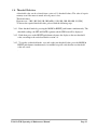
3. Operating Instructions
3.1. Preparation for Use
Remove the instrument from the shipping container and check for any physical damage. In
the case of damage, report it immediately to MGP Instruments.
Do not attempt to install or operate damaged equipment since safety and performance may
be affected
3.2. Starting-up
Ensure that the detector is connected to the meter. Press the ON/OFF push-button. For pre1999 models, when the meter is turned on, it carries out a short self-test procedure indicated
by displaying all the segments on the display and emitting two beeps for a short period.
Following the test, the meter is ready for use. For 1999-present models, when the meter is
turned on, it emits a single beep, then followed by three shorts beeps indicating the self-test
procedure is completed and the meter is ready for use.
Note: When the meter is turned on, the low range GM Tube is not connected. As a safeguard,
the high-range GM Tube is connected (>600 mR/hr) in the event that the user is in a high
exposure rate field. If the radiation field measurement is lower than 600 mR/h, the meter
switches to the low range GM Tube.
3.3. General Functions
3.3.1. Exposure rate Display
The TelePole measures Exposure rates in the range of 0.0 1mR/h to 999 R/h.
Readings are displayed in digital and analog mode. The ranges in the bar graph are changed
automatically and the units displayed correspond to both, the digital and analog display. The
bar graph measuring response is quicker than the digital display response since the latter
averages the readings.
3.3.2. Automatic Range Switching:
The detector includes two Geiger: Low range - ZP-1201 (or equivalent), and high range ZP-1301 (or equivalent).
In a field of 0.01 mR/h to 800 mR/h both geigers are connected and the field is measured by
the low range geiger. In case the radiation field is higher than 800 mR/h (Optional Firmware
‘070301’ 2500 mR/h), the low range geiger is disconnected, and the radiation field is
measured by the high range Geiger. The switching between the low and high range geigers
is done at 800 mR/h when the radiation field increases (low range geiger is disconnected),
and at 600 mR/h (Optional Firmware 2000 mR/h) when the radiation field decreases (low
range geiger is connected).
TelePole WR/ Operating & Maintenance Manual
Page 9
Geiger Type
ZP 1301
High Range
Overflow
alarm
ZP 1201
Low Range
Field
0.01 mR/h
600 mR/h
800 mR/h
1000 R/h
Geiger Type Optional 070301 Firmware
ZP 1301
High Range
Overflow
alarm
ZP 1201
Low Range
Field
0.01 mR/h
2000 mR/h
2500 mR/h
1000 R/h
3.3.3. Reading reset:
Exposure rate - While in Exposure rate mode, a long press on the RESET push-button
enters the meter into the FREEZE mode (for peak measuring). An additional long press
performs a momentary reset of the Exposure rate readings.
The reset function provides a rapid means of discharging the Display reading and enables
accurate measurement of low level Exposure rates.
3.3.4. Audible announcements:
When the meter is turned on, the radiation field intensity is observed by the click rate. A
long press on the MODE push-button toggles the click on and off.
Each push-button press is accompanied by an audible beep.
In case of threshold alarm or failure alarm the audible alarm is activated. To mute the
audible alarms press the RESET push-button.
TelePole WR/ Operating & Maintenance Manual
Page 10
3.4. Threshold Selection
A threshold value can be selected from a series of 11 threshold values. The value is kept in
memory even if the meter is turned off or if power is lost.
Threshold values:
Exposure rate : 2.00, 5.00, 50.0, 100, 500 [mR/h], 1.00, 10.0, 200, 400, 800, 999 [R/h]
To choose the required threshold value, proceed with the following steps:
3.4.1. Enter threshold mode by pressing the MODE & RESET push buttons simultaneously. The
threshold readings, the SET and RATE segments and the SPK icon will be displayed.
3.4.2. Each short press on the RESET push-button advances the display to the next threshold
value, according to the order described in section 3.4.
3.4.3. To exit the set threshold mode, save and set the new threshold value, press the MODE &
RESET push buttons simultaneously. An audible beep will verify that the new threshold
value was saved.
.
TelePole WR/ Operating & Maintenance Manual
Page 11
3.5. Alarms
a. Detector alarm: The Err. LCDs and SPK icon will blink on the display in three cases:
1. The detector is disconnected.
2. The detector high voltage power supply is defective.
3. The detector is located in a background radiation field < 600 mR/h and the low range
Geiger is defective.
4. If the detector is located in a radiation field higher than 800 mR/h and the meter displays
the following sequence of readings: 800 mR/h, 600 mR/h, 0.00 mR/h - this indicates the high
range geiger is malfunctioning.
Note: It is recommended to check the meter and the detector with a calibration source, to
ensure correct operation. Check:
Background field during two minutes,
50 mR/h for the low range Geiger,
5.00 R/h for the high range Geiger.
To mute the audible alarm, press the RESET push-button.
b. Battery alarm: If battery voltage decreases below 2.2V, the battery and SPK icons blink
on the display, and an interrupted audible alarm is activated.
To mute the audible alarm, press the RESET push-button.
c. Overflow alarm: If the displayed Exposure rate is over 999 R/h, the O.F. LCDs and SPK
icon will blink on the display and an interrupted audible alarm will be activated. To mute the
audible alarm, press the RESET push-button.
d. Threshold alarm for Exposure rate: If the Exposure rate reading exceeds threshold value,
the RATE LCDs and SPK icon will be displayed, accompanied by an audible beep.
Pressing the RESET push-button mutes the audible alarm, but the RATE LCDs, the SPK
icon and the reading continue to be displayed, until the reading decreases to 75% of threshold
value. In case the reading exceeds threshold value and then decreases to below 75% of the
threshold value, the RATE LCDs, the SPK icon and the beep sound will automatically
cancel, even though the RESET push-button has not been pressed.
TelePole WR/ Operating & Maintenance Manual
Page 12
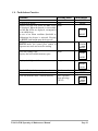
3.6. Push-buttons Function
Function
Pressing mode
Meter on/off
Speaker beeps on/off
Long
Operates laser bar-code reader, the bAr. LCDs Short
are displayed. When the barcode is successfully
read the Go. LCDs are displayed, accompanied
by an audible beep.
In case of an alarm condition (threshold or
malfunction) the beeper is activated. Pressing
the RESET push-button turns the beeper off.
In Exposure rate mode, the first press enters the Long
FREEZE mode, the second press returns to
Exposure rate mode and resets the reading.
Stores the reading value.
Displays the left available memory space.
Push-buttons
ON/OFF
MODE
B.CODE
RESET
B.CODE
RESET
Short
STORE
LIGHT
Displays back light on/off.
Long
STORE
LIGHT
Threshold Set mode / measurement mode.
Selects one of eleven threshold values.
Clear data from the meter’s internal memory.
TelePole WR/ Operating & Maintenance Manual
Simultaneously
Short
Two sequential
Long pressings
(10 sec)
MODE + RESET
RESET
B.CODE
RESET
Page 13
3.7. Battery Replacement
Note: The battery compartment is located on the lower right side of the TelePole’s meter.
3.7.1. Slide out the battery compartment cover in the direction of the arrow (open). See Fig. 31.
3.7.2. Insert two C-type alkaline batteries with the correct polarity.
3.7.3. To close of the battery compartment, press the batteries down, place the compartment
cover on the battery edge, press the batteries down with the compartment cover and slide
the cover into place along the side slots.
Using an External Power Supply
Power can be supplied to the meter in one of two ways:
1. Ordinary batteries - default use. When an external 3V DC power supplies is connected, the
internal batteries will be disconnected.
2. Rechargeable batteries - on request. A 2.9V to 3.2V external power supply charges the
batteries. A jumper on the printed circuit performs the interchange.
Warning: Ensure to connect the external power supply with the correct polarity, as indicated
on the instrument battery compartment.
Figure 3-1. TelePole Battery Compartment
4. Communication
4.1. Survey Mapping Communication
The TelePole is compatible with the survey mapping software. An External Laser Scanner or
a Smart Wand (laser pen) may perform the scanning of the bar code. The bar-code reader is
connected to serial port COM-1 located on the instrument rear panel.
TelePole WR/ Operating & Maintenance Manual
Page 14
Following is the operating procedure.
4.1.1. A short press on the B.CODE push-button turns the bar-code reader on. Three short
beeps will be sounded. The bAr. LCDs are displayed.
4.1.2. If the bar-code reading is successful, the Go. LCDs will be displayed.
4.1.3. To save the instrument data (ID, time, date, value, unit, comments) perform a short
press on the STORE push-button.
4.1.4. After the saving operation, the amount of available memory space remaining is
displayed.
4.1.5. To load data from the TelePole to the survey mapping software, connect the RS232 of
the PC to COM-1 on the TelePole rear panel by a special communication cable (supplied
with the software system). Downloading data from the TelePole to the PC clears the
instrument’s memory. TelePole can store up-to 380 readings (or 1550 optional with
extended memory).
Warning: To purposely clear data from the TelePole’s memory press the B.CODE pushbutton for 10 seconds, the current available memory space is displayed for an additional
ten seconds. An additional press on the B.CODE push-button within the ten seconds erases
the data. The instrument indicates it by four audible beeps and 380 m, the new available
memory space is displayed.
4.2. WRM Communication
The WRM transmitter is connected to the serial port COM-2 located in the instrument’s rear
side via a standard telephone cable. The additional operations like transfer of data, are
performed automatically. The WRM communication protocol includes accumulated dose
data. Note: The TelePole does not measure accumulated dose, therefore instead of
transmitting the accumulated dose value, it transmits the digits 888888.8.
4.3. WRM2 Communication
The WRM2 optional kit(WR2-A??) is connected via two screws on the meter box and is
powered by the same power supply that powers the TelePole. The transmission interval
level is defaulted 4 seconds and can be changed using the Meter View software with the
communication cable designed for the TelePole and the Ram Ion and the baud rate to the
Telepole when using the WRM2 radio is set to 19,200 BPS. The WRM2 kit is available to
older instruments built 2006 or later and require new firmware and two wired jumpers
installed. Instruments built in 2007 or greater are pre-configured for the WRM2 Telepole
kit. Note: The TelePole does not measure accumulated dose, therefore instead of
transmitting the accumulated dose value, it transmits the digits 888888.8.
TelePole WR/ Operating & Maintenance Manual
Page 15
4.4. RS-232 and WRMPlus Connection
Communication parameters
Baud rate:
Parity:
Hardware handshaking:
Software handshaking:
Stop bit:
Prefix:
Suffix:
Data format:
COM-1
9600
None
None
None
One
01
04
8 data bits
COM-2
300
None
None
None
One
LF
CR
8 data bits
4.5. With Optional WRM2 Kit Data Connection
Communication parameters
Baud rate:
Parity:
Hardware handshaking:
Software handshaking:
Stop bit:
Prefix:
Suffix:
Data format:
COM-1
19,200
None
None
None
One
01
04
8 data bits
TelePole WR/ Operating & Maintenance Manual
COM-2
19,200
None
None
None
One
LF
CR
8 data bits
Page 16
5. Calibration Instructions
5.1. Preface
5.1.1. Calibration Factors
To improve the linearity, the TelePole uses five calibration factors: The two lower factors
are for the low range Geiger, from 0.01 mR/h to 800 mR/h; and the other three are for the
high range Geiger, from 1000 R/h to 600 mR/h.
Note: Optional Switching 070301 Firmware; the two lower factors are for the low range
Geiger, from 0.01 mR/h to 2500 mR/h; and the other three are for the high range Geiger,
from 1000 R/h to 2000 mR/h.
The calibration factors will be displayed on the meter, as follows:
F1 - first calibration factor for low range.
F2 - second calibration factor for low range.
F3 - first calibration factor for high range.
F4 - second calibration factor for high range.
F5 - third calibration factor for high range.
F1 and F3 are used to compensate the Geiger sensitivity tolerances.
F1 for the low range Geiger (ZP1201) and F3 for the high range Geiger (ZP1301).
F2, F4 and F5 are used to compensate the Geiger dead time tolerances.
F2 for the low range Geiger (ZP1201) and F4, F5 for the high range Geiger (ZP1301).
5.1.2. Calibration Ranges
F1 has to be set at 50 mR/h ± 20 mR/h
F2 has to be set at 350 mR/h ± 50 mR/h.
Optional Switching 070301 Firmware: F2 factor must be set at the range of 800 to 1500
mR/h when using the optional switching firmware
F3 has to be set at
10 R/h ± 2 R/h
F4 has to be set at 200 R/h ± 60 R/h
F5 has to be set at 600 R/h ± 100 R/h
Measured (displayed) readings are calculated by one of the following two formulas,
depending on the intensity of the radiation field:
Low range: N(mR/h) = [n*F1 + dead time correction {n*F2}]/17
High range, up to 300 R/h: N(R/h) = [n*F3 + dead time correction {n*F4}]/300
High range, over 400 R/h: N(R/h) = [n*F3 + dead time correction {n*F5}]/300
TelePole WR/ Operating & Maintenance Manual
Page 17
Where
n is the detector frequency obtained in the radiation field.
N is the updated measurement reading.
Between 300 R/h to 400 R/h, a weighted average of F2 and F3 is used as the dead time
correction factor. The calculation of the "averaged factor" and the corresponding
measurement formula follow:
x = (last N(R/h) - 300)/100
Last N = previous measurement reading
F average = (1-x)* F4 + x* F5
N(R/h) = [n*F1 + dead time correction {n*F average}/300
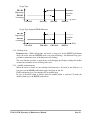
The following graph illustrates the ranges over which F2, F3 and F average are used as the
TelePole's dead time correction factor:
Dead time
correction factor
F3
F2
F average
Field [R/h]
300
400
1000
5.2. Calibration Procedure (See Appendix 2)
5.2.1. To set the TelePole to the calibration mode unscrew the calibration screw located on the
back of the meter. Turn the internal switch to the calibration position.
In a field higher than 10 mRh, the meter automatically enables only the display and setting
of the appropriate factor, depending on the field intensity.
F1 if the probe head is in a field higher than 10 mR/h and lower than 100 mR/h.
F2 if the probe head is in a field higher than 100 mR/h and lower than 800 mR/h.
Optional switching 070301 Firmware: F2 factor must be set at the range of 800 to
1500 mR/h when using the optional switching firmware
F3 if the probe head is in a field higher than 800 mR/h and lower than 50 R/h.
F4 if the probe head is in a field higher than 50 R/h and lower than 350 R/h.
F5 if the probe head is in a field higher than 350 R/h
5.2.2. Expose the detector to a radiation field of 50 mR/h ±20 mR/h.
The display will show:
→ F1 → F (factor) → mR/h (reading) →
↑__________________________________↓
TelePole WR/ Operating & Maintenance Manual
Page 18
Change the factor by pressing the RESET or LIGHT push-button to obtain the desired
reading.
5.2.3. Expose the detector to a radiation field of 100 mR/h to 800 mR/h. Note: Use calibration
points 800 mR/h to 1500 mR/h when using the optional switching 070301 firmware
(2000 mR/h – 2500 mR/h).
The display will show:
→ F2 → F (factor) → mR/h (reading) →
↑_______________________________↓
Change the factor by pressing the RESET or LIGHT push-button to obtain the desired
reading.
5.2.4. Expose the detector to a radiation field of 10 R/h ±2 R/h.
The display will show:
→ F3 → F (factor) → R/h (reading) →
↑_______________________________↓
Change the factor by pressing the RESET or LIGHT push-button to obtain the desired
reading.
5.2.5. Expose the detector to a radiation field of 200 R/h ±60 R/h.
The display will show:
→ F4 → F (factor) → R/h (reading) →
↑_______________________________↓
Change the factor by pressing the RESET or LIGHT push-button to obtain the desired
reading.
5.2.6. Expose the detector to a radiation field of 500 R/h to 700 R/h.
The display will show:
→ F5 → F (factor) → R/h (reading) →
↑_______________________________↓
Change the factor by pressing the RESET or LIGHT push-button to obtain the desired
reading.
5.2.7. Set the TelePole to the operating mode, turn the internal switch to the operating position.
5.3.
CPU Unit Pulser Check (Option Only)
Note: Although it is possible to "calibrate" the TelePole using a series of input pulses (from a
pulser), the manufacturer strongly recommends against this. Checking instrument response
to input pulses ensures that the meter's CPU is operating properly, but indicates nothing
about the detector. The manufacturer recommends that the instrument is calibrated
according to the previous section (5.2 Calibration procedure), by exposing the probe head to
known radiation fields and adjusting factors appropriately, which ensures that both the
detectors and the CPU are operating properly.
TelePole WR/ Operating & Maintenance Manual
Page 19
The CPU unit counts the input pulses, calculates dead time, averages the results, and displays
the reading.
To check the CPU unit "calibration" perform the following procedure:
5.3.1. Disconnect the detector telephone connector from the meter.
5.3.2. Adjust the pulser output to obtain a 5 Volts amplitude and 10 µsec width pulse.
5.3.3. Connect the pulser output as follows: (+) to pin 1 and (-) to pin 2.
Option: A more convenient and easier way to perform this step is by using the TelePole
Pulser Adapter. Proceed as follows:
- Connect the adapter telephone cable to the detector connector (Det.) on the TelePole.
- Connect the pulser signal output to pin 4 on the adapter board.
- Connect the pulser ground output to pin 3 on the adapter board.
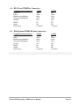
5.3.4. First, turn the meter on, and then turn the pulser on. Ensure to obtain the base unit
reading (±10%) according to the following table:
Tab1e 1 - Low Range Geiger
Input Frequency <Hz>
17
170
2000
4000
5000
6000
6300
Display <mR/h>
1.00
10.0
141
365
534
730
804*
* Switch to high range geiger
Table 2 - High Range Geiger
Input Frequency <Hz>
300
3200
10.000
30.000
40.000
50.000
60.000
75.000
Display <R/h>
1.00
10.7
39.2
183
323
525
839
O.F. (overflow)
These results are valid only when all factors equal to 1.
TelePole WR/ Operating & Maintenance Manual
Page 20
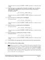
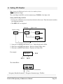
6. Setting ID Number
Note: Setting the ID # must be done only by an authorized user.
The ID # includes 6 digits.
The second digit in the ID # sets the instrument type. TelePole’s first digit is (0).
Setting and Checking the ID #:
• Unscrew the calibration screw located on the back of the meter. Turn the internal switch to
the calibration position.
• The SET LCD's are displayed.
ID# digit
Digit’s value
Display reading
0.00
2
d1.6
1
d1.9
3
d2.0
1
1 - Long press on MODE push-button (5 sec.) - In/out display and set ID #.
2 - Short press on LIGHT push-button - Increases displayed digit value.
3 - Short press on RESET push-button - Displays next digit value.
For example:
906325
Id1.9
= ID #
Id4.3
The default ID# is:
9 06 001
Designates Portable Instrument
Serial # of Instrument
Year
Designates Instrument type: TelePole
TelePole WR/ Operating & Maintenance Manual
Page 21
7. Electronic Block Diagrams Description
See block & wiring diagram DRW# 12850-50-00.
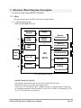
7.1. Meter
The meter unit includes the CPU and the Power Supply boards.
7.1.1. CPU Board Description
DRW #12850-40-00, PC #1942.
Display
Decoder
J6
Latch
input
1/2
Touch
Panel
Display
Driver
Latch
output
J2
CPU
J3
On / Off
80C32
J1
ElectroLuminescence
UART &
Communication
J5
Communication
J4
EEPROM
Speaker
EPROM
J6
1/2
Extension Card
CPU Board Block Diagram
On /Off Circuit (Q3, Q4, Q5)
A momentary short between pin J3/1 and J3/2 switches Q3 and Q4 on.
The battery voltage powers the power supply circuit.
U5/5 is set to “1” (in software), Q3 is switched on, and as a result the meter is turned on.
An additional momentary short between J3/1 and J3/2 sets U5/6 to “0” through Q5. U5/5
is set to “0” and the meter is turned off.
TelePole WR/ Operating & Maintenance Manual
Page 22
Speaker Circuit (U13)
The speaker circuit is activated in the following cases:
a. Threshold level exceeding.
b. Malfunction.
c. Push-button pressing approval.
d. The speaker clicks frequency is proportional to the radiation field intensity.
A 3 KHz signal on pin U13/3 activates the speaker. Two ports control the speaker:
Port 1 - alarm, pin U3/9
Port 2 - speaker on, pin U3/19
For threshold level exceeding and malfunction:
U3/9 - “0”
U3/19 1sec 1sec
For push-button pressing approval:
U3/9 - “0”
U3/19 100msec
For clicks activation in relation to the radiation field intensity:
U3/9 - “1”
U3/19 - “1”
To mute the speaker:
U3/9 - “0”.
U3/19 - “1”
Input & Output Latch
Two 74HC373 IC‘s are used for the input/output signals. The IC’s are connected to the
CPU BUS.
Input signals - U9, address - 8200H
Output signals - U3, address - 8100H
Output Signals
0 - U3/2
1 U3/5
2 - U3/6
3 U3/9
4 U3/12
5 U3/15
6 U3/16
7 U3/19
external/internal detector (optional)
low range / high range geiger
Electro-luminescence
speaker alarm
not in use
not in use
enables VCC for barcode laser reader
speaker on
TelePole WR/ Operating & Maintenance Manual
Page 23
Input Signals
0U9/3
1 U9/4
2 - U9/7
3 U9/8
4 U9/13
5 U9/14
6 U9/17
7 U9/18
MODE push-button
RESET push-button
LIGHT push-button
low battery
not in use
calibration mode
internal geiger (optional)
PC communication
Touch Panel
The touch panel push buttons are connected to the micro-controller chip in the CPU
board via input latch, except the on/off push-button that is connected to the on-off
circuit.
Display (U17, U18)
DRW # 12850-40-00 sheet 2.
The display shows the meter readings and messages.
The display driver (U17) receives clock and serial data from the CPU and transmits it in
parallel to the display in three back planes.
U18 - Rotem’s custom display especially designed for the RAM ION and Telepole
meters. The display includes 3-character 7-segment, 2 decimal points, bar graph and data
segments.
Electro-luminescence (EL, T1, Q1, Q6)
Pressing the LIGHT push-button turns on the display illumination.
U3/6 is set to “1” and activates T1 that supplies 100V AC.
EPROM Circuit (U2, U5) & Extension Card
U2 - 74HC 373, Address A0 - A7, latch from AD0 - AD7 .
U5 - 27C 256, EPROM contains software code.
The extension card, DRW # 12850-41-00, is installed on the EPROM socket.
The extension card includes EPROM, NOVRAM, Reset and Watchdog circuit.
U2 - NOVRAM: DS1243 8K byte, or DS1244, 32K byte.
The NOVRAM contains: SRAM, clock, calendar and battery back up, used for storing
the SMARTS data.
U3 - MAX1232, watchdog and reset circuit. The micro-controller receives a reset signal
in two cases:
a. When the meter is turned on.
b. In case of software failure.
Pulses are sent from U6/2 to U3/7 as long as operation runs ok. In case of a fault
detection in software, the pulses stop and a reset signal is obtained on U3/6.
TelePole WR/ Operating & Maintenance Manual
Page 24
CPU Circuit (U6)
The micro-controller circuit manages all the meter activities.
EEPROM Back up Memory (U1)
The X2C04 is a 512-byte serial EEPROM (Electrically Erasable Prom).
The EEPROM stores threshold values, ID number and calibration factors values.
Communication Circuit
The CPU board contains two separate communication ports. One is the micro-controller
communication port used for the SMARTS communication:
J4/1 TxD - This is the serial data line transmitted from the meter. The logic level swings
are 0 to 5 Volts, and can be described as RS-232 TTL level. This circuit is able to drive
TTL, LSTTL, and CMOS inputs.
J4/2 RxD - This is the serial data line received in the meter. The meter accepts serial
data either in RS-232 signal levels (low: -3 to -15 Volts, high: +3 to 15 Volts) or TTL
levels (low: 0.8 Volts, high: 2.0 Volts).
J4/3, 6 - ground
J4/4 - + 5V
UART & Communication
The other communication port is used for the WRM system or COMBO system.
U12 - 82510 is connected to the CPU BUS, address 8700H.
J5/1 TxD - This is the serial data line transmitted from the meter. The logic level swings
are 0 to 5 Volts, and can be described as RS-232 TTL level. This circuit is able to drive
TTL, LSTTL, and CMOS inputs.
J5/2 RxD - This is the serial data line received in the meter. The meter accepts serial
data either in RS-232 signal levels (low: -3 to -15 Volts, high: +3 to 15 Volts) or TTL
levels (low: 0.8 Volts, high: 2.0 Volts).
J5/3 - ground
J5/6 - + 5V
J5/7 - trigger from the WRM transmitter
The communication port receives a trigger from the WRM transmitter and transmits the
data to the WRM system.
RxD
200msec.
TxD
TelePole WR/ Operating & Maintenance Manual
Page 25
Decoder
U11 - 74HC138, sets addresses for the input/output IC’s and UART IC.
Address ranges from 8000H to 8700H.
Three addresses are used:
8100 - input latch U3
8200 - output latch U9
8700 - UART 82510 U12
TelePole WR/ Operating & Maintenance Manual
Page 26
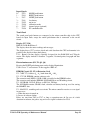
7.1.2. Power Supply
DRW #12850-42-00.
Option
High Voltage
Converter
J6
Calibration
Switch
J2
3V to 5V
Converter &
Low Battery
Identification
Internal Geiger
Internal / External
Geiger
J3
J5
J1
3V to 12V
Converter
WRM
Communication
Geiger
J8
H.V. Board Block Diagram
High Voltage Converter & Internal Geiger (optional)
The high voltage converter and internal geiger components are installed on the board
only when the internal geiger is used. As well, a short is performed on jumper E3. When
the microcontroller identifies the short on E3 via J5/5, the internal geiger is activated.
High Voltage Circuit for the Internal Geiger
The H.V. circuit includes an ORAM 5525 transformer, a voltage multiplier (D4, D5, D6,
C7, C3), and an RV4192 switching regulator.
R10 and R9 are voltage feedback for the switching regulator.
The high voltage, 500V ±5% generated in the H.V. circuit is transmitted to the geiger.
When the Geiger is positioned in a radiation field, positive pulses
are obtained on
pin K1 of the Geiger. These pulses are shaped and amplified by Q1, Q4 and RC
components.
TelePole WR/ Operating & Maintenance Manual
Page 27
Internal / External Geiger Selection
U2 - 74HC132 and port J2/4 are used to select between the internal and external geiger.
J2/4 enables to select between operation and display of internal geiger or external geiger.
J2/4 = “0” - internal geiger
J2/4 = “1” - external detector.
3V to 5V Converter & Low Battery Identification
MRX756 (U1) and RCL components convert the battery voltage to 5V, (which is) the
meter’s main power supply.
Input voltage range: 1.7V to 3V DC.
Output voltage range: 5V ±0.1V.
Low battery identification is performed by U1. When the battery voltage reduces below
2.0V on pin LB1, LB0 (pin 4) on U1 resets to “0”.
3V to 12V Converter
MAX771 (U4) and RCL components convert the battery voltage to 12V that is aimed for
the speaker circuit.
7.2. WRM Communication
Q2, Q3 and resistors adapt between the WRM transmitter and meter voltage levels.
E1 (1-3) should be shorted.
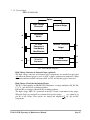
7.3. Wide Range Detector
DRW # 12852-40-00
H.V.
GM 1201
Low
Range
H.V.
Power supply
500V ±20V
Pulse
Shaper
Select
Geiger
Driver
H.V.
GM 1301
High
Range
Pulse
Shaper
Pulse
Driver
J1
Detector Block Diagram
TelePole WR/ Operating & Maintenance Manual
Page 28
High Voltage Power Supply
The H.V. board includes an ORAM 5525 transformer, a voltage multiplier (D1, D2, D3,
C8, C11), an RV4192 switching regulator.
R3 and R4 are voltage feedback for the switching regulator.
H.V. range: 500V to 550V DC. The high voltage is aimed for both geigers.
Pulse Shaper
Each geiger includes a pulse shaper circuit.
Q3 and RC for the low range geiger 1201.
Q5 and RC for the high range geiger 1301.
7.3.1. Select Geigers
The detector includes two geigers: Low range - ZP-1201 (or equivalent), and high range ZP-1301 (or equivalent).
In a field of 0.01 mR/h to 800 mR/h both geigers are connected and the field is measured by
the low range geiger. In case the radiation field is higher than 800 mR/h, the low range
geiger is disconnected, and the radiation field is measured by the high range geiger.
The switching between the low and high range geigers is done at 800 mR/h when the
radiation field increases (low range geiger is disconnected), and at 600 mR/h when the
radiation field decreases (low range geiger is connected).
Geigers selection is performed via J1/2 control line.
Geiger Type
ZP 1301
High Range
Overflow
alarm
ZP 1201
Low Range
Field
0.01 mR/h
600 mR/h
800 mR/h
1000 R/h
Pulse Drive
Q2, Q4 and R23 drive the detector pulses to the meter.
TelePole WR/ Operating & Maintenance Manual
Page 29
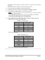
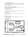
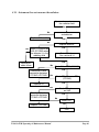
8. Troubleshooting
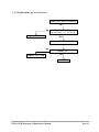
8.1. Meter does not power turn ON
Meter does not turn on
Yes
Check power on/off circuit
(PC 1942) section 8.2
O.K
Check 5V power supply circuit
(PC 1945) section 8.3
O.K
Check CPU reset circuit
(PC 1944) section 8.4
O.K
Replace CPU Card
TelePole WR/ Operating & Maintenance Manual
Page 30
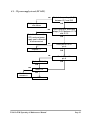
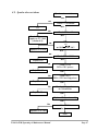
8.2. Power on/off circuit (PC 1942)
No
Check battery voltage (2−3)V
O.K
Replace battery
No
Fix
Check battery connector
& wires
O.K
No
Battery, connector or
wire failure
Check voltage between
J1/1 & J1/2 = (2−3)V
O.K
No
Press on/off p.b. and check
J3/1 & J3/2 short
O.K
Replace touch panel
No
Replace Q3
Press on/off p.b.
Check (0.2 − 0.5)V DC
on Q3 collector
O.K
Replace Q4
No
Go back to
section 8.1
Meter OK?
Yes
END
TelePole WR/ Operating & Maintenance Manual
Page 31
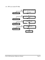
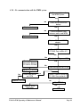
8.3. 5V power supply circuit (PC 1495)
No
O.K
Battery, connector or
wire failure
No
Flat cable between the
CPU card and power
supply card is defected
or disconnected
Press on/off p.b. and check
voltage (2÷3)V between J2/7,8
and J2/1,3
O.K
No
Replace L1
Check pulses on U1
pin 8
O.K
No
Replace D3 & U1
Check battery voltage (2÷3)V
between J9/1 and J9/3
Check 5V on U1
pin 6
O.K
O.K
No
Go back to
section.8.1
Meter OK
Yes
END
TelePole WR/ Operating & Maintenance Manual
Page 32
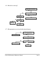
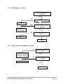
8.4. CPU reset circuit (PC 1944)
No
Check correct connection
between extension card and
CPU card
Fix
O.K
No
Replace U3
Check on U3/6
O.K
No
Check on U5/6
O.K
Replace U5
No
Replace C4
Check on U4/4
O.K
END
TelePole WR/ Operating & Maintenance Manual
Page 33
8.5. 12V power supply circuit (PC 1945)
No
O.K
Battery, connector or wire
failure
No
Flat cable between the
CPU and power supply
cards is defected or
disconnected
Press on/off p.b. and check
voltage of (2−3)V between
J2/7,8 and J2/1,3
O.K
No
Replace L1 and Q5
Check pulses on D2
anode
O.K
No
Replace D2 & U1
Check battery voltage (2−3)V
between J9/1 and J9/3
Check 5V on U1
pin 6
O.K
O.K
No
Meter OK
Replace
PC 1945
END
TelePole WR/ Operating & Maintenance Manual
Page 34
8.6. Meter does not turn off
Meter does not turn off
Yes
No
Press on/off p.b. and check
(0.2 − 0.5)V on Q5 collector
O.K.
Replace Q5
Replace CPU Card
No
Replace
CPU Card
Meter OK?
Yes
END
8.7. Meter parameters are not saved in the internal memory
No
Replace CPU Card
Check pins 5 & 6
on U1 output pulses
O.K.
Replace U1 (X24C04)
No
Replace CPU Card
Meter OK ?
Yes
END
TelePole WR/ Operating & Maintenance Manual
Page 35
8.8. Display turns off or is incorrect
Display turns off or is incorrect
Yes
No
Replace CPU Card
Check pulses output
on U17 pins 1, 2, 14, 15, 16
O.K.
Replace U18 LCD 106198
No
Replace CPU Card
Meter O.K.?
Yes
END
TelePole WR/ Operating & Maintenance Manual
Page 36
8.9. Speaker does not alarm
Speaker does not alarm
Yes
No
Check E1 Unshorted
O.K.
Fix
No
Check 12V on L1
O.K.
Check 12V power
supply on PC 1945
(section 8.5)
No
Check
1sec
on U8/9 and 0V U8/1
Replace CPU card
O.K.
No
Check 5V on U13/4
O.K.
Replace U8
No
Replace U13
Check U13/3
3KHz ±10% pulses
O.K.
No
Replace U8
Check U8/11
3KHz ±10% bursting pulses
O.K.
No
Replace Q8
Check existing pulses
on Q8 collector
O.K.
Replace S1 (speaker unit)
O.K.
No
Replace CPU Card
Meter O.K.?
Yes
END
TelePole WR/ Operating & Maintenance Manual
Page 37
8.10. No communication with the WRM system
No Communication with
the WRM System
Yes
No
Check WRM transmitter
battery
O.K.
Replace battery
No
Check telephone cable
between meter and WRM
O.K.
Replace or fix cable
Replace "Meter to WRM"
adapter
O.K.
Check WRM trigger on
PC1945. See section 8.11
O.K.
No
Check pulse trigger on J5/7
O.K.
Check and fix wire
connection between
PC1942 & PC1945
No
Check data pulses on U12/6
O.K
Replace U12 (82510)
No
Check data pulses
on U12/6
O.K
Check Tx data to WRM on
PC 1945. See section 8.12
O.K
Replace CPU card
No
Meter O.K.?
Replace WRM
transmitter
TelePole WR/ Operating & Maintenance Manual
Yes
O.K
END
Page 38
8.11. WRM trigger checking
Check WRM trigger on
PC1945
O.K.
No
Check E1 (1-3) is shorted
O.K.
Fix
No
Check pulse trigger
on J4/8
Replace WRM
transmitter
O.K.
No
Check pulse trigger
on J5/7
O.K.
Replace Q2
END
8.12. Check Tx Data to WRM on PC 1945
No
Check and fix wire
connection between
PC1942 & PC1945
Check data pulses on
J5/1
O.K.
No
Check data pulses
on J8/2
Replace Q3
O.K.
END
TelePole WR/ Operating & Maintenance Manual
Page 39
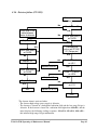
8.13. Instrument does not measure the radiation
System does not measure
the radiation field
Yes
No
Check cable between meter
and detector
Replace or fix cable
O.K.
No
Replace detector
O.K.
No Check TTL pulses on
U2/5 (PC1945) when
the detector is in the
radiation field
Detector failure
See section 8.14
O.K.
Detector or
cable failure
No
Check and fix wire
connection between
PC1942 & PC1945
Check 5V on U2/1 (PC1945)
O.K.
No
Check TTL pulses on TP1
(PC1945)
O.K.
Replace U2
No
Check and fix wire
connection between
PC1942 & PC1945
Replace CPU card
Check TTL pulses
on U8/4
O.K.
No
Meter OK?
Yes
END
TelePole WR/ Operating & Maintenance Manual
Page 40
8.14. Detector failure (PC 2003)
Detector failure
Yes
No
Check and fix the
cable between
meter & detector
O.K.
No
Replace T1
Check (500÷550)V
on R4/R5
O.K.
O.K.
Check positive
pulses on ZP1201
G1 (Geiger pin)
Check (500÷550)V
on R4/R5
O.K.
No
No
Replace U1
Replace Q3 & Q1
Check (500÷550)V
on R4/R5
No
Replace U3
Replace Card
Replace Q2 or Q4
Check TTL pulses
on U3/8
O.K.
No
O.K.
Check TTL pulses
on U3/1
O.K.
No
END
Check 5V on C2
Check TTL pulses
on J1/4
O.K.
END
The detector alarm is activated when:
- The detector high voltage power supply is defective.
- The detector is located in a background radiation field and the low range Geiger is
defective. If the detector is located in a radiation field higher than 800mR/h, and the
meter displays the following readings sequence: 800 mR/h, 600 mR/h, 0.00 mR/h this indicates high range Geiger malfunction.
TelePole WR/ Operating & Maintenance Manual
Page 41
8.15. Display Back Light doesn’t turn ON
Display Back light doesn’t
turn on
Yes
Press LIGHT pushbutton
during 2 sec.
O.K.
No
Check U9/7 or J3/6
while pressing
Replace touch panel
O.K.
No
Check 5V on U3/6
O.K.
Replace CPU card
No
Check 8V ±1V on T1 pin input
O.K.
Replace Q1 & Q6
No
Check 80V AC on T1 pin out
=
Replace T1
O.K.
Replace electro
Luminescence
O.K.
END
TelePole WR/ Operating & Maintenance Manual
Page 42
9. Mechanical Instructions
July 2007
9.1. TelePole WR meter exploded drawing and parts list
10
7
2
1
15
7
14
16
3
11
4
6
12
8
14
33
21
23
22
20
PC1942
26
24
PC194
27
PC1945
25
1
PC2003
13
16
9
TelePole WR/ Operating & Maintenance Manual
28
32
30
29
Page 43
TelePole WR Part Numbers
P/N
RTM-9113
RTM-3010
RTM-3017
RTM-3013
RTM-3045
RTM-3022
RTM-3044
Part Name
Complete TelePole WR
Meter bracket & 4 screw
Carrying strap
2 strap clip
Pole assembly
Complete pole assembly
4 Segment pole with fastening nuts
Collar, aluminum (external) set of 3
Clutch, plastic (internal), set of 3
Rear lid (underneath grip)
Grip
Rear strap holder
Heat shrinkable tube
Front strap holder
Pole to Detector adapter & 2 screw
Telephone coiled cable 120 cm(internal)
Meter assembly
Complete meter assembly
Mechanical parts
Meter case complete without electronics
boards
Battery cover
Electronic parts
Touch panel
CPU board with LCD
LCD display
RTM-3021
Memory board with EPROM
24
RTM-3023
Power supply board
25
RTM-3024
Flat cable 10p
26
RTM-3025
Flat cable 4p
27
RTM-3020
RTM-3014
RTM-4037
RTM-4036
RTM-3018
RTM-3008
RTM-3007
RTM-3009
RTM-3012
RTM-3050
RTM-3019
RTM-3046
RTM-3011
RTM-1023
TelePole WR/ Operating & Maintenance Manual
Part #
4
10
7
15
8a,8b,8c
8a,8b,8c
12
2
1
3
6
16
13
33
14
20
21
22
23
Page 44
Detector assembly
RTM-3049
Complete detector assembly
11
Detector board 2003 with 2 Geiger, rear
flange (and 2 screws), damping sponge
and mica cover
28
RTM-7000
Detector board 2003 without Geiger
32
RTM-4022
Geiger1201
29
RTM-4035
Geiger1301
30
RTM-3051
Detector sleeve/cover & 3 screws
9
RTM-3048
TelePole WR/ Operating & Maintenance Manual
Page 45
9.2. Preparation for Use
Note: See the telescopic pole construction scheme for reference.
NOTE: The manufacturer recommends that the end user/owner to perform periodic
inspections of the telescopic pole, collars, and clutches to ensure proper operational
use and safety.
9.2.1. Check the condition of the segments, collars, and clutches (under collars) as follows: Hold
the telescopic pole with both hands horizontally. Wear the carrying strap (15) over the head
and on the shoulder, one hand holding the pole and the other hand free to adjust the strap to
the optimal length. See Figure 7-1.
Figure 7-1. Telescopic pole holding
9.2.2. Check the segments' fastening/collar nuts (8: a, b, c) by turning them slightly, to make
sure there are no disturbances or wore clutches.
9.2.3. Check the pole segments (9, 10, 11, 12) by extending them all the way out, following the
proceeding steps:
9.2.4. Ensure the three fastening nuts (8: a, b, c) are locked.
9.2.5. Loosen nut (8c) by turning it counter-clockwise (looking from the meter side).
9.2.6. Pull segment (12) all the way out.
9.2.7. Tighten nut (8c).
9.2.8. Loosen nut (8b).
9.2.9. Pull segment (11) all the way out.
9.2.10. Tighten the middle nut (8b).
9.2.11. Loosen nut (8a).
TelePole WR/ Operating & Maintenance Manual
Page 46
9.2.12. Pull segment (10) all the way out.
9.2.13. Tighten nut (8a)
9.2.14. Ensure that proper tension is on each collar in order for the segments to stay in one
position when moving the instrument up and down and side to side with the
segments completed extended.
9.2.15. Now collapse each segment back inwards in the reverse order.
TelePole WR/ Operating & Maintenance Manual
Page 47
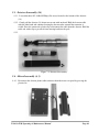
9.3. Detector disassembly (14)
9.3.1. Loosen the three NC 4-40x3/8 Philips flat screws located at the bottom of the detector
(14).
9.3.2. Gently pull the detector (14) about two cm out with one hand. Hold the detector cable
with the other hand and continue drawing the detector tube out until the connector is
visible. Press the connector's plastic clip to disconnect the cable from the detector. Hold the
cable end with a clip to prevent it from entering back into the pole.
9.3.3.
Figure 7-2. Detector disassembly
9.4. Meter disassembly (4, 5)
9.4.1. Disconnect the detector phone cable connector from the meter rear panel by pressing the
plastic clip.
TelePole WR/ Operating & Maintenance Manual
Page 48
Figure 7-3. Meter disassembly
9.4.2. Loosen the four NC 6-60 Philips screws fastening the meter holder (4) to the meter.
9.4.3. The meter and holder are now detached from the telescopic pole. See Figure 7-3.
9.5. Meter Holder Assembly (4)
9.5.1. Position the meter (5) on a flat and clean surface with the display facing down.
9.5.2. Position the telescopic pole on the meter rear cover.
9.5.3. Position the meter holder (4) on the meter (5) while the cable groove is facing the telephone
socket side.
9.5.4. Ensure the cable goes through the inside space created between the meter holder and the
meter rear cover.
9.5.5. Attach the meter holder (4) to the heat shrinkable tube (3) and tighten the four screws.
9.6. Detector Assembly (14)
9.6.1. Connect the cable to the detector. Insert the detector (14) back into the pole’s end.
9.6.2. Tighten the three NC 4-40 x 3/8 Philips flat screws located on the detector bottom part (14),
use lock tight material to secure the screws.
9.7. Pole Segments Assembly
9.7.1. Insert the segments (9, 10, 11, 12) one into the other according to their diameter size, from
the largest to the smallest one, while the threads are facing forward in the detector direction.
9.7.2. Insert plastic rings into the two biggest fastening nuts (8a, 8b).
9.7.3. Screw the two fastening nuts (8a, 8b) on the segments (9, 10), in order of their size (first
the bigger nut 8a), and then fasten them.
9.7.4. Insert the smallest plastic ring on the last segment (12), push the ring backwards, next to the
thread of segment (11).
9.7.5. Insert the third nut (8c) and screw it on segment (11).
9.8. Pole Segments Disassembly
9.8.1. Perform the steps in section 7.7 in the reverse order.
TelePole WR/ Operating & Maintenance Manual
Page 49
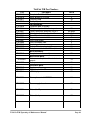
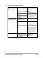
9.9. Telescopic Pole Troubleshooting Table
Symptom
Probable Cause
Segments are stuck and the Superficial damage,
pole doesn’t extend
crushed, (squeeze)
segments and / or adjusting
nuts.
Cable is caught inside the
segments.
Sand or chips of dirt
caught inside, between the
segments.
After extending out the
Squeezing or bending of
segments, they cannot be
the segments and/or
retrieved back.
adjusting nuts.
Fastening nuts are stuck.
Cable is caught inside the
pole.
Cable damage.
Instrument stored with the
telescopic pole extended
for a long period. Cable
loses flexibility.
TelePole WR/ Operating & Maintenance Manual
Required Action
Visually inspect segments
and/or nuts for external
damages.
Replace damaged parts.
Shake the pole up and
down to release the cable.
Remove any foreign debris
from the sections.
Replace telescopic pole.
Loosen the nut and remove
it to inspect visually. If the
plastic ring underneath is
damaged, replace it.
Disassemble the detector.
Disconnect the cable and
pull it in and out several
times to release it, at the
same time, extend and
collapse the segments
several times.
Store the instrument with
the telescopic pole
collapsed.
Page 50
Appendix 1
Upgrading TelePole Instruments from High Range and Low Range
to Wide Range
1. WR Detector
• Replacing the detector with a new wide range detector.
• Pull gently the detector about two cm out with one hand. Hold the detector cable with the
other hand and continue drawing the detector tube out until the connector is visible. Press
the connector plastic clip to disconnect the cable from the detector. Hold the cable end
with a clip to prevent its entering back into the detector tube.
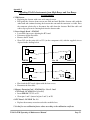
2. Power Supply Board - PC #1945
• Loosen the four screws adjusting the PC board.
• Disconnect all the flat cables.
• Remove the PC board.
• Short J2/2 (on the print side) to J3/3 (on the component side) with the supplied wire as
depicted in the drawing below.
J3
U2
flat cable
1945 PS
J2
C19 C18
Ver. 1.0
1945 CS
J3
U2
J2
TP3 TP2
flat cable
1945 PS
Ver. 2.0
TP1
1945 CS
• Place back the PC board, tighten with the four screws.
• Reconnect the flat cables.
3. Memory Extension Card - PC #1944 Ver. 2.0 or 2.1 and
CPU Board - PC #1942 Ver. 2.0 or 2.1)
• Insert EPROM 27C512 on U1.
• Short pins 1 and 2 (instead of pins 2 and 3) on E3.
4. CPU Board - PC #1942 Ver. 1.0
• Replace the memory extension card with a modified one.
5. Set the five new calibration factors values according to the calibration certificate.
TelePole WR/ Operating & Maintenance Manual
Page 51
Appendix 2
Generic TelePole Calibration
1. It is possible to set/change all the factors outside the radiation chamber.
2. When the radiation field is lower than 10 mR/h, it is possible to change all the factors.
3. When in the calibration mode and the external radiation field is lower than 10 mR/h,
pressing the MODE push-button can switch between the different factors.
4. Suggested procedure:
4.1
Turn the internal switch to the calibration position.
4.2
Press the MODE push-button twice to enter the calibration mode.
4.3
Expose the TelePole to a radiation field of 50 mR/h ±20mR/h. The meter will be
automatically set to factor F1. Now the factor can be changed either by pressing the
RESET or LIGHT push-button or taking the meter outside the radiation chamber and
adjust the factor F1.
Place the TelePole back inside the radiation chamber and expose it to a radiation field
of 50 mR/h. Check that the meter's reading and the radiation field are equal.
4.4
Expose the TelePole to a radiation field of 350 mR/h ±50mR/h. The meter will be
automatically set to factor F2. Now the factor can be changed either by pressing the
RESET or LIGHT push-button or taking the meter outside the radiation chamber, the
radiation field should be lower than 10 mR/h. Notice if the current displayed radiation
factor is F2. If the factor is not F2 press the MODE push-button to switch to F2.
Adjust F2 by pressing the RESET or LIGHT push-button.
Place the TelePole back inside the radiation chamber and expose it to a radiation field
of 350 mR/h. Check that the meter's reading and the radiation field are equal.
4.5
Expose the TelePole to a radiation field of 10 R/h ±2 R/h. The meter will be
automatically set to factor F3. Now the factor can be changed either by pressing the
RESET or LIGHT push-button or taking the meter outside the radiation chamber, the
radiation field should be lower than 10 mR/h. Notice if the current displayed radiation
factor is F3. If the factor is not F3 press the MODE push-button to switch to F3.
Adjust F3 by pressing the RESET or LIGHT push-button.
Place the TelePole back inside the radiation chamber and expose it to a radiation field
of 10 R/h. Check that the meter's reading and the radiation field are equal.
4.6
Expose the TelePole to a radiation field of 350 R/h ±50 R/h. The meter will be
automatically set to factor F4. Now the factor can be changed either by pressing the
RESET or LIGHT push-button or taking the meter outside the radiation chamber, the
radiation field shold be lower than 10 mR/h. Notice if the current displayed radiation
factor is F4. If the factor is not F4 press the MODE push-button to switch to F4.
Adjust F4 by pressing the RESET or LIGHT push-button.
Place the TelePole back inside the radiation chamber and expose it to a radiation field
of 350 R/h. Check that the meter's reading and the radiation field are equal.
TelePole WR/ Operating & Maintenance Manual
Page 52
4.7
Expose the TelePole to a radiation field of 600 R/h ±100 R/h. The meter will be
automatically set to factor F5. Now the factor can be changed either by pressing the
RESET or LIGHT push-button, or taking the meter outside the radiation chamber, the
radiation field should be lower than 10 mR/h. Notice if the current displayed radiation
factor is F5. If the factor is not F5 press the MODE push-button to switch to F5.
Adjust F5 by pressing the RESET or LIGHT push-button.
Place the TelePole back inside the radiation chamber and expose it to a radiation field
of 600 R/h. Check that the meter's reading and the radiation field are equal.
5. When adjusting F2, F3, F4, F5, and the TelePole is taken out of the radiation chamber, it
can either remain at the current factor or switch back to F1, depends on the radiation field
falling speed. If the meter switches to F1, press the MODE push-button to switch to the
current factor, each press will precede the factor to the next factor.
MODE
F1
MODE
F2
TelePole WR/ Operating & Maintenance Manual
F3
F5
Page 53
Appendix 3
Rotem Meter View Software (RMV)
Preface
Rotem Meter View Software (RMV) is a WINDOWS 95 based program, aimed to download
ROTEM's meters measurements to a PC. The meters are: RAM ION, TelePole and RAM DA-2000.
Communication between the meter and the PC can be performed in two modes:
On-Line - The meter downloads the measured data into the PC at intervals time set by the user.
Off-Line - Data is stored in the meter (up to 347 strings) and then downloaded into the PC.
Required Equipment
PC based WINDOWS 2000/XP/Vista and RS-232 communication port.
MGPI's customized communication cable.
Download Meter View from the MGP Instruments web site www.syodys.com .
Software Installation
Insert the CD into the CD drive (or the first floppy diskette into the floppy drive). Select Start, then
run and select the setup.exe file.
Operating Instructions
1. Connect one of ROTEM's meters to the PC via RS-232 communication port, by the customized
communication cable.
2. Start the Meter View software.
TelePole WR/ Operating & Maintenance Manual
Page 54
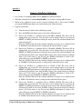
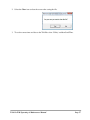
3. Select ‘Setting’ to set the Communication Port.
4. Select Get legend to fill the legend parameters.
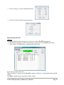
Data Download to PC
Off Line
1. Store the ID location in the meter by a short press on the SPEAKER push-button.
2. Store the measurements and date in the meter by a short press on the LIGHT push-button.
3. Select ‘Data’ “Get offline data’ to download the meter's data.
In the displayed table notice that:
When an asterisk (*) appears on the Over Thr. column, it indicates a reading higher than threshold
setting.
The Status column indicates threshold or failure alarms.
TelePole WR/ Operating & Maintenance Manual
Page 55
Bytes status description:
32
16
OFLO
dose
OFLO
rate
8
Over thr.
rate
4
Over thr.
dose
2
1
Detector
fail
Low
battery
For example:
Status = 1 - low battery
Status = 8 - over threshold rate.
Status = 9 - low battery and over threshold rate.
On-Line
1. Select ‘Set Interval’ for WRM2 Radio.
2. Select Start, the meter downloads the data into the PC at intervals time set by the user.
The Start icon is replaced by the Stop icon.
Note: When software is in the on-line mode, the Get Data icon is blocked since it belongs to
the off-line mode.
3. To exit of the on-line mode select the Stop icon (green color). The Start icon (orange color) is
displayed on the Meter View window.
General Functions
1. To save the data file select the Save icon and type the File Name. The saved data file can be
opened using MS NotePad or Spreadsheet software.
TelePole WR/ Operating & Maintenance Manual
Page 56
2. Select the Clear icon to clear the screen after saving the file.
3. To set the correct time and date to the TelePole select ‘Utility’ and then Send Time.
TelePole WR/ Operating & Maintenance Manual
Page 57
Appendix 4
TelePole WR - List of Electronic Drawings
Available Upon Request
DRW #12850-40-00 - Ver. 2.1 - CPU - DigiLog (sheet 1), PC #1942
DRW #12850-40-00 - Ver. 2.1 - CPU - DigiLog Display (sheet 2), PC #1942
DRW #12850-41-00 - Ver. 2.1 - CPU - DigiLog Extension Card, PC #1944
DRW #12850-42-00 - Ver. 4.0 - Power Supply, PC #1945
DRW #12852-40-00 - Ver. 2.0 - GM Detector, PC #2003
DRW #12852-50-00 - Ver. 2.0 - Wiring Diagram
DRW #12850-45-00 - Ver. 2.0 – CPU – Digilog Display
TelePole WR/ Operating & Maintenance Manual
Page 58