1
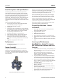
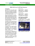
CWGFC Product Data Sheet D301293X012 June 2012 ControlWave® GFC Gas Flow Computer Featuring the “Express” Electronics Platform When requirements call for an integrated “all in one box” chart replacement or flow computer, ControlWave® GFC, from Emerson Process Management, is a cost effective, competitive solution. Unlike chart replacements, ControlWave GFC is also able to meet your automation needs and easily supervises a tworun metering and regulating station or plunger lift operations at a well site. Hardware/Packaging Features 32-bit ARM9 platform is capable of multiple flow computing and process automation operations. Gauge pressure or DP/P sensor assembly can be removed and replaced independently of the “top end” electronics. Precision RTD interface provides very accurate measurement. Very low power consumption minimizes costs of solar/battery power systems, which are also integrated in the package. Three serial communication ports are standard. Standard I/O includes 2 DI/PI. Optional I/O expansion includes 2 DI/DO, 4 DI, 2 DO, 2 High-Speed Counter Inputs, 3 AI and 1 AO. Integral LCD with optional 25-key keypad allows you to view and change configurable parameters on site, without packing a PC. Broad selection of modem and wireless communications options are available. Firmware/Software Features ControlWave GFC is pre-programmed to meet API 21.1 requirements for a two-run metering station with networking via BSAP or Modbus. Web-style menu pages are pre-configured for all user operations. Using our ControlWave Designer, IEC 61131-3 programming environment, any user or third party can modify the standard application or create a completely customized program and the full support from Emerson is available every step of the way. Additional standard application programs will be introduced on a continual basis. Remote Automation Solutions ControlWave GFC Application Areas ControlWave GFC is appropriate to all applications for “chart replacements” and flow computers, particularly including those that require process control or extension to two meter runs. For example: Production wells Injection wells Production optimization applications Off-shore platforms Separation plants Compressor stations Storage facilities Transmission metering stations Distribution/LDC metering/gate stations ControlWave GFC Package Overview ControlWave GFC is delivered in a compact Lexan enclosure that has provisions for not only the electronics but also a display/keypad, DP/P/T transducer assembly, battery/solar power system, and a broad selection of modem and radio communications options. CWGFC June 2012 Item Descriptions and Specifications Standard equipment includes Lexan housing with 2-line LCD, single board electronics assembly, and the standard API 21.1 flow measurement application program. Standard I/O count is 2 DI/PI (Pulse Inputs). Also included in the base product are interfaces to Emerson’s gauge pressure or multivariable, DP/P sensor assembly, an RTD interface, AUX power output (e.g. to switch power to a radio), and shunt regulator for solar panel charging of an internal lead acid cell battery. Most two-run systems use the integrated sensor assembly for the first run and an external, smart multivariable transmitter, such as the 3808 MVT (which includes the exact same sensor assembly), for the second meter run. If the sensor assembly requires a repair, you can change it out and continue operating with the electronics, including flow information, alarms and historical archives, all intact. Emerson recommends that you practice “depot level” service. In other words, the sensor assembly is removed and replaced at the shop rather than out at the site. You can also specify all of the following: Integral gauge pressure or multivariable (MVT) DP/P sensor assembly, and upper range limits Bendable RTD assembly, pre-wired Thermowell A two-line LCD with no pushbuttons, two-line LCD with two pushbuttons, or a four-line LCD with 25-key keypad I/O card, including 2 DI/DO, 4 DI, 2 DO and 2 HSC/DI and, optionally, an additional 3 AI, 1 AO Hazardous area approval — Class I, Division 2 Choice of integral, battery, and solar power systems Choice of standard model modem or radio that is installed on an internal bracket. Standard radios are those that are commonly available from Freewave and MDS. Polyphaser surge suppressor for the radio Each sensor assembly has a nine-digit part number, which can be used to specify a replacement part. Performance Accuracy and Performance Specifications — Gauge Pressure or MVT Differential Pressure and Static Pressure Computation Accuracy: 0.01% Corrected Flow, including all input values Sensor Assembly Using the sensor assembly integrated in the instrument package is the easiest implementation for a single meter run; however, the standard application program also allows use of external transmitters with or without the integrated sensor assembly. Physical Specifications — Sensor Assemblies MVT Flange and Center Section and Gauge Pressure Sensor Housing Material: 316 SS Flange Bolt Material: 316 SS Diaphragm Material: 316 SS Fill Medium: DC 200 Silicone MVT Flange Process Connections: ¼-inch NPT female Gauge Pressure Sensor Process Connection: ½-inch NPT male Connects to the Processor Board via a dedicated SPI bus cable Combined effects of nonlinearity, nonrepeatability, and hysteresis at reference pressure and over the operating temperature range. DP: ±0.075% of calibrated span or 0.02% of URL, whichever is greater; SP: 0.075% of calibrated span or 0.02% of URL, whichever is greater. Temperature Effect on Static and Differential Pressure: ±0.21% URL maximum combined shift of zero and span with an ambient temperature change of 60ºC (108ºF) Static Pressure Effects on Differential Pressure: Zero Error: ±0.1% URL, for a change in static pressure of 1000 psi; Span error: ±0.1% URL, for a change in static pressure of 1000 psi Long Term Stability at Constant Conditions: ±0.1% URL/Year maximum MVT Mounting Position Effect: ±2-inch H2O maximum, which can be calibrated out. Power Supply Effect: ±0.005% of URL maximum for any change within input power supply voltage range Ripple and Noise: Per ISA 50.1 section 4.6 DP/P Multivariable (MVT) Sensor Assembly 2 www.EmersonProcess.com/Remote CWGFC June 2012 MVT Assembly Static Pressure Orientation can be defined. The ControlWave GFC can be set to automatically sequence through this list. For a multivariable sensor assembly, you can specify whether the static pressure sensor is oriented to the right or to the left from the point-of-view of a user looking at the front of the ControlWave GFC. Following the AGA3-1992 convention, we refer to the static pressure sensor location as the “upstream” (a.k.a. “high side”) location. Integral Enclosure and LCD/Keypad 2-button display example The standard LCD provides two lines and operates in a continuous cycle mode. One of two optional configurations can be selected instead: 4-line x 20-character LCD with either a 2-button or 25-button keypad. Both display/keypad assemblies have the same “footprint” on the front door. Features — Display/Keypads 4-line by 20-character backlit liquid crystal display Adjustable display contrast Membrane keys with tactile feedback Self-adhesive overlay mounts to the enclosure door or panel (ControlWave GFC package is delivered with this assembly installed on the door) Easy configuration via ACCOL III Function Block Scrolling display mode Adjustable timer turns off display when not in use Specifications — Display/Keypads Window size: 1.1 inches H x 3.1inches W (2.8 cm H x 7.9 cm W) Character size: 4 mm H x 3 mm W Dimensions: 7.4 inches H x 5.5 inches W (18.8 cm H x 14.0 cm W) Power consumption: 2.5 mA @ 3.3 V (0.008 watts) Operating Temperature: -4 to 158ºF (-20 to 70ºC) 25-button display example The 25-button display/keypad performs the same functions and additionally allows the operator to view and modify ControlWave GFC inputs, process variables, calculated variables, setpoints, tuning parameters, and outputs used in a measurement or control application. Status bits include the alarm state, alarm acknowledge, control, and manual (Auto/Man). Providing access to such variable information allows you to have complete control over the process operation. Mounting Hardware You can specify optional hardware for pole-mounting or wall-mounting. The “pole-mount” kit includes two wallmounting plates and two pipe clamps. Without the mounting hardware, the ControlWave GFC is suitable for process-mounting to a direct-mount manifold. Note that this is appropriate only for models with MVT sensor assemblies. A unit with a gauge pressure sensor should not be process-mounted. Processor/Main Electronics The processor electronics assembly consists of a single circuit board, which is installed on the far left-hand side in the enclosure. ControlWave GFC Standard Application Program LCD Panel with 25-button keypad The 2-button display allows an operator to view site, configuration, and process data. The screens are organized in a series of lists. The operator can select a list and then manually scroll through the data. Additionally, a “scroll list” www.EmersonProcess.com/Remote The ControlWave GFC comes preloaded with the 1 — 2 run M&R load application. ControlWave GFC is shipped with the program (.profile) loaded in Flash and the Flash Configuration Program (FCP) also loaded. You interface to the Standard Application Program via a series of straight-forward web-style menu pages. 3 CWGFC June 2012 The Hourly Data Log holds one record for every contract hour. Hourly logs hold 840 entries or 35 days; this ensures that the previous period of hourly data is always resident in ControlWave GFC FLASH memory. The following items are stored in the Hourly Data Log: Overview of the Standard Application Program: Uses pre-configured web-style menu pages for user readings, configuration, and maintenance. PC menu pages can be modified and new pages configured to work with a modified application load. The program uses TechView Calibration Utility for the calibration of all transducers, including the integral MVT and external transmitters (e.g. 3808 MVT). The PC menu pages, calibration utility, and program load are all included on the BSI Config CD. Standard configuration is a one-to-two run station meter type. Corrected Volume Uncorrected Volume Accumulated Energy Average Static Pressure Average Temperature Average Differential Pressure Average Specific Gravity Average Heating Value Flow Time Uncorrected Count Each log entry also contains the date and time. ControlWave GFC has an Hourly Historical Log for each run. Daily Historical Data Log The Daily Data Log holds one record for every contract day. The contract hour may be changed by the user. The daily log holds 62 entries; this ensures that the previous calendar month of daily data is always resident in ControlWave GFC FLASH memory. The following items are stored in the Daily Data Log: The user interface to the Standard Application Program is via a series of straight-forward web-style menu pages. 4 Flow calculations include the following: AGA3-1992 with selectable AGA8 Gross or AGA8 Detail AGA3-1985/NX-19 AGA7/NX-19 AGA7 with selectable AGA8 Gross or AGA8 Detail Auto Adjust AGA7/NX-19 Auto Adjust AGA7 with selectable AGA8 Gross or AGA8 Detail AGA9 Allows you to select the integral sensor assembly or an external transmitter for a single run configuration or as run 1 in a multiple run configuration. External transmitters can be interfaced via RS-485 or analog inputs. Includes run switching Includes an auto-selector, PID flow/pressure control algorithm per run or per station Resides on a BSAP SCADA network Supports a sampler and an odorizer Hourly Historical Data Log Corrected Volume Uncorrected Volume Accumulated Energy Average Static Pressure Average Temperature Average Differential Pressure Average Specific Gravity Average Heating Value Flow Time Uncorrected Count Each log entry also contains the date and time. ControlWave GFC has a Daily Historical Log for each run. Periodic Historical Data Log The periodic data log holds one record for every log interval. Log interval is 15 minutes. The Periodic Historical Data Log holds 1440 records, or four days of 15 minute data. The following items are stored in the Periodic Historical Data Log: Flowing Differential Pressure Flowing Static Pressure Flowing Temperature Frequency Each log entry also contains the date and time. ControlWave GFC has a Periodic Historical Data Log for each run. www.EmersonProcess.com/Remote CWGFC Audit Trail Alarm and Event Storage ControlWave GFC keeps an Audit Trail Buffer capable of storing the most recent 500 Alarms and the most recent 500 Events. Internally, these buffers are maintained separately to prevent recurring alarms from overwriting configuration audit data. Externally, they are reported to the user as a single entity. Both operate in a circular fashion with new entries overwriting the oldest entry when the buffer is full. The following circumstances cause an entry to be made in the Audit Trail Buffer: Any operator change to a ControlWave GFC configuration variable Any change in the state of a ControlWave GFC alarm signal A system restart Certain other system events Includes a nominations function Allows you to select engineering units from a broad variety, including English and metric Interfaces to a chromatograph and provides energy throughput as well as composition information (note that same port is allocated for either a chromatograph or external transmitters. Self Diagnostics ControlWave GFC periodically runs a series of diagnostics to verify the operational status of various system components. The tests include transducer parameters, main and backup battery voltages, software sanity checks, and other indications of system health. An appropriate alarm is generated if any test fails. Communication Port Configuration for the Standard Application Program COM1 — See Specifications in the Table on page 8. The external PC port connector, accessible on the bottom of the front door, is connected to this port on the CPU. COM2 — See Specifications in the Table on page 8. The standard application program is compatible with an external communication device (via RS 232) or standard model radio. If a standard model radio is included, the model will also include a cable that connects this port, on the CPU, to the RS 232 port on the radio. COM3 — See Specifications in the Table on page 8. The standard application program assumes that 3808 MVT multivariable transmitters for meter run measurement are to be interfaced to this port. www.EmersonProcess.com/Remote June 2012 The standard application program supports a chromatograph, but a Flash Configuration change is required to allow the chromatograph to be interfaced to COM3. Power System, Charge Regulator and AUX Output You can choose from a variety of internal power systems that includes lithium batteries and rechargeable lead acid cell batteries, the latter of which are matched with solar panels as charging sources. All associated electronics are included on the Processor/Main Electronics board, which is located on the left-hand side of the enclosure. Related to the power system, a charge regulator circuit and an auxiliary output (AUX Output) are standard in ControlWave GFC. Bendable RTD You can choose a bendable RTD that is attached to the ControlWave GFC via an armored cable of 6-foot, 15-foot or 25-foot length. The individual wires attach to a terminal block on the Processor/Main Electronics board. The terminal block accepts up to three wires. Normally, this RTD is used to provide the process temperature input, but the standard application program also allows you to select an external temperature transmitter, instead. The bendable RTD is a “one size fits all” solution that is perfect for most applications and excellent for depot-level inventory situations in which the ultimate installation (and, therefore, thermowell depth) is not necessarily known. The 12-inch probe can quickly be inserted in a thermowell, whereupon you can tighten the included fitting to lock it in place and bend the excess length out of the way. Note that a thermowell is required for this bendable RTD. RTD Interface Information A three-wire platinum RTD per DIN 43760 is supported. The temperature, T, in degrees Celsius is calculated using the Resistance vs. Temperature Tables according to the DIN EN 60751 standard for Class A and B RTDs. ControlWave GFC supports the full range in the DIN standard, -40 to 660ºC. The DIN EN 60751 equation is: RT = Ro * (1 + AT +BT2) Where: A = 3.9083 x 10⁻³ ºC-1 B = -5.775 x 10⁻⁷ ºC-2 Ro = 100 Ω 5 CWGFC June 2012 In addition, you may enter the Ro, A, and B coefficients of a custom calibrated RTD, another platinum standard or a different material (Nickel, Balco, or Copper). During the RTD calibration, you are able to set the coefficients, restore the factory default for these coefficients, and calibrate the internal reference resistor. Thermowell Options for RTD For new installations, or those lacking a thermowell, you can choose one of three lengths of thermowell for the RTD. I/O Configuration Note that the base I/O (2 DI/PI) is located on the Processor/Main Electronics board. Also, the RTD input and MVT (Multivariable sensor) interface are located on the Processor/Main Electronics board. Additional I/O circuitry is located on an optional I/O card that plugs in to the Processor/Main Electronics card. You can choose between the minimum I/O configuration of 2 DI/DO, 4 DI, 2 DO and 2 HSC/DI or an expanded version, which additionally includes 3 AI or 3 AI and 1 AO point. It is important to match the radio-ready configuration with the specific radio you expect to install because cables and connections for the antenna, RS 232 port, and power vary by radio model. Modem Specifications The auto-dial/auto-answer modem is the same Cermetek model that is used in the TeleFlow products. This modem provides a sleep mode that conserves power while allowing it to wake up when a call comes in. Function: Provides PSTN (Public Switched Telephone Network) communications. Operating Modes: Sync or Async. 2-wire switched network, Half or Full Duplex. Line Type: Two-wire loop start lines. Modem Configuration: “AT” based commands. Data Rate: V.32 bis — 9600 bps, V.32 — 9600 bps, V.22 bis — 2400 bps, V.22 — 1200 bps or 600 bps, V.21 — 300 bps, Bell 103J — 300 bps, Bell 212A — 1200 bps. Telephone Functions: Dialling and answering by AT commands. Automatic answering is also programmable. Approvals: Telephone - FCC Part 68 (also suitable for approval within Canada). Trans. Output Levels: -10 dBm fixed (USA) or 0 to15 dBm adjustable (firmware dependent). PSTN Arrangements: Loop Start arrangement (transmission output does not exceed -10 dBm). Allows connection to any voice telephone jack. Isolation: Data Access Arrangement (DAA) with 1000 Vac (Modem to PSTN). Sleep Mode Current: 0.5 mA (max) @ 12 V (Input Voltage); 1.0 mA (Max) @ 6 V (Input Voltage) Surge Capability: Withstand surge of 100 A with 10 x 160 microsecond waveform. Temperature: Operating Range: -40º to +60ºC (-40º to 140ºF); Storage Range: -40º to +85ºC (-40º to 185ºF) Relative Humidity: 15% to 90%, non-condensing What is the difference between a pulse input (PI) and highspeed counter input (HSC)? The HSC circuitry includes debounce, which is useful with form ‘C’ relays, such as those in some pulser devices. A PI does not include the debounce circuitry and is, therefore, not recommended with relays. Note that in the HSC inputs, the debounce can be enabled/disabled by the user and they are shipped disabled. We recommend that users select the 3 AI / 1 AO configuration if use of analog I/O is anticipated in the future because addition of the points requires a change-out of the I/O card due to hazardous area certification requirements that can be done only at the factory. Polyphaser Option For Radio If a radio is specified, you can select whether or not a Polyphaser surge protector is included. Emerson always recommends the Polyphaser. Modem or Radio Option For specifications on the radios, please refer to the Emerson Process Management web site, www.EmersonProcess.com/Remote, where individual data sheets are available in pdf format. Radios are standard models, which are widely available from Freewave and MDS. Note that modems and radios are all allocated to the network port, COM2, and are, thus, mutually exclusive. Since some users prefer to procure the radios separately, Emerson offers radio-ready configurations for each of the models. Radio-ready models include literally everything except for the radio. The mounting bracket as well as all cables and connections are in place. The user or integrator/installer must simply mount the radio to the bracket and make connections. 6 Radio Specifications Radio Power Consumption NOTE: When conserving power, ControlWave GFC turns power to the radios completely off instead of operating them in the sleep mode. Freewave FGR Spread Spectrum Radio Figures at 12 Vdc: Receive: 75 mA Transmit: 500 mA Idle: 20 mA www.EmersonProcess.com/Remote CWGFC MDS TransNet 900 Spread Spectrum Radio Figures at 13.8 Vdc: Receive: 115 mA Transmit: 510 mA MDS models 4710 and 9710 Licensed, UHF Radios with figures at 13.8 Vdc: Receive: 125 mA Transmit: 2000 mA MDS entraNet 900 IP Radio Figures at 13.8 Vdc: Receive: 100 mA Transmit: 510 mA MDS iNet 900 Ethernet/IP Radio Figures at 13.8 Vdc: Receive: 203 mA Transmit: 580 mA Product Family Compatibility June 2012 ControlWave Designer with ACCOL III To minimize your engineering and development time, we have adopted the international standard for controller programming, IEC 61131-3. ControlWave Designer is a fully IEC 61131-3-compliant programming environment for the ControlWave family of products. ControlWave Designer includes all five IEC 61131-3 process languages for batch, continuous and discrete control: Function Block Diagram, Structured Text Sequential Function Chart, Ladder Logic Diagram, and Instruction List. ControlWave Designer includes an extensive library of more than 200 basic IEC 61131-3 functions and function blocks common to many IEC 61131-3 based products. ControlWave GFC is compatible with Emerson’s ControlWave family. It is fully software compatible with ControlWave XFC, ControlWave EFM, ControlWave Micro and the ControlWave Process Automation Controller. The ControlWave Process Automation Controller provides the highest I/O capacity and supports up to three Ethernet ports as well as redundancy. These include: This family compatibility is a major benefit to users whose operations include a number of larger installations in addition to those that require flow computers. ControlWave family products are capable of all measurement and control functions at sites such as major, custody-transfer metering stations, compressor stations, off-shore platforms, processing plants, and storage facilities. You will not only appreciate the similarity in much of the hardware, but will also find the documentation, networking, and software compatibilities as key to your asset management. Open Standards for Programming, Network Configuration and Communication Only ControlWave brings the perfect combination of industry standards to minimize learning, engineering, and implementation costs. By adhering to such industry standards as Ethernet, TCP/IP, Microsoft® Windows®, COM/DCOM, FTP, OLE and ActiveX, ControlWave is able to achieve the highest degree of openness in control system architecture and bring the optimal process efficiency and productivity needed to ensure a successful system implementation. www.EmersonProcess.com/Remote Counters, Timers Ladder diagram functions — coils and contacts, etc. Numerical, Arithmetic and Boolean functions — Sine, Cosine, Add, Sub, Square Root, And, Or, etc. Selection and Comparison — Min, Max, Greater than, Equal, Less than, etc. Type conversions — Integer to Real, Boolean to Word, etc. ACCOL III In addition to the basic functions and function blocks, ControlWave Designer brings the benefit of many years experience in measurement and SCADA to the ACCOL III function block library. ACCOL III includes over sixty function blocks that are valuable for use in oil and gas and process measurement and control applications. Further, ACCOL III is designed to take full advantage of the significant features offered by ControlWave. Briefly, this library includes function blocks for: AGA gas flow and API liquids calculations Audit, Archive, File Handling Average, Compare, Totalize Scheduling and Sequencing PID and Lead/Lag In addition, ControlWave ensures data integrity, in the event of a communication interruption, by storing critical timestamped alarm and historical data in the controller memory. This data is then securely retrieved when communication is restored. 7 CWGFC June 2012 ControlWave GFC Gas Flow Computer CPU Module ControlWave GFC Clock Backup Battery Type 32-bit ARM9TDMI RISC Core Processor, 14 MHz or 33 MHz Memory Boot 512 KB Flash 8 MB SRAM 2 MB, battery backed Battery backed Serial Real Time Clock Accuracy 1 second/day at 25ºC Speed 14 MHz or 33 MHz 300 mA-Hour Lithium Coin Cell, 9000 Hour Expected Backup Time Communications Module Communication ports COM1 (RS 232) COM2 (RS 232) COM3 (RS 232 or RS 485, 2-wire or 4-wire) Quantity 1 Type Physical Interface via DB-9 connector, which is internally linked to the circular, Alden connector on the bottom of the enclosure door Baud Rate 115.2 KBd Quantity 1 Type 8-pin terminal block. Supports RTS, CTS, DTR, DCD and DSR modem control signals Baud Rate 9600 Quantity 1 Type 5-pin terminal block Baud Rate 9600 Inputs/Outputs RTD Input 8 Quantity 1 (available in 6-ft, 15-ft, or 25-ft length) Type 3-wire platinum RTD per DIN 43760 Sensing Range -40 to 660°C (-40 to 933°F) Conversion Accuracy ±0.05°C or ±0.05% of reading, whichever is greater Ambient Temperature Effect ±0.01°C/ºC max Long Term Stability at Constant Conditions ±0.25ºC/month max www.EmersonProcess.com/Remote CWGFC Pulse Counter/Discrete Inputs (on CPU Module) Discrete Inputs (optional) Discrete Outputs (optional) www.EmersonProcess.com/Remote June 2012 Quantity 2 non-interrupting inputs Type Internally sourced dry contact single ended inputs Scan Rate 1/s Input filter 20 μs Voltage range Internally sourced dry contact input - 3.3 Vdc On State <1.21 V Off State >2.07 V Input current 200 μA nominal at 3.3 V per input Surge Suppression meets ANSI/IEEE C37.90-1978; 30 V transorb between signal and ground Terminations Pluggable Terminal block accommodates up to 16 gauge wire size When used as pulse input Frequency Rate 0 to 10 kHz Debounce None Accumulator 16 bit Quantity 4 DI-only and 2 points that are selectable as inputs or outputs Type Internally sourced dry contact input - 3.3 Vdc Scan rate (maximum) Once per 250 ms Input Configuration Dry contact Input Filtering 15 ms Input current for DI points 1 to 4 (those that are DIonly): configurable as 60 μA for low power applications or 2 mA nominal at 3.3 V per input Input current for DI points 5 to 6 (those that are selectable as DI or DO): configurable as 200 μA for low power applications or 2.2 mA nominal at 3.3V per input Voltage DI 1-4 On State <1.0 V Off State >2.0 V Surge Suppression Meets ANSI/IEEE C37.90-1978; 30V transorb between signal and ground Terminations: Pluggable terminal block accommodates up to 16 gauge wire size Quantity 2 DO only and 2 that are selectable as input or output, per-point Configuration Open Drain MOSFET Operating voltage range 10 to 31 V dc 9 CWGFC June 2012 High Speed Counter/Discrete Inputs 5,6 Analog Inputs (optional) Maximum load current 400 mA at 16 V and 400 mA at 30 V Maximum update rate Once per 250 ms Electrical isolation None Surge Suppression meets ANSI/IEEE C37.90-1978; 30 V transorb between signal and ground Terminations Pluggable terminal block accommodates up to 16 gauge wire size Type 2, also operable as DI points Type Dry contact Frequency range 0 to 10,000 Hz or 0 — 30 Hz; switch selectable Input Range Internally sourced dry contact input Input filtering 20 μs or 1 ms; switch selectable Accumulator 16 bit Maximum scan rate (program scan of the accumulator) Once per 250 ms Input current 200 μA per input at 3.3 V On State <1.21 V Off State >2.07 V Surge suppression Meets ANSI/IEEE C37.90‐1978; 30 V transorb between signal and ground Terminations Pluggable terminal block accommodates up to 16 gauge wire size Quantity 3 Resolution 14 bit Input configuration Externally sourced single-ended inputs, jumper selectable 4 to 20 mA or 1 to 5 Vdc Input impedance 1 MΩ, 4 to 20 mA Input filtering 12 Hz Maximum scan rate Once per 250 ms Channel settling time 600 ms to be within 0.01% of input signal Input accuracy 0.1% of span at 25ºC 0.2% of span -40 to 70ºC 10 Surge Suppression Meets ANSI/IEEE C37.90-1978; 30 V transorb between signal and ground Terminations Pluggable terminal block accommodates up to 16 gauge wire size www.EmersonProcess.com/Remote CWGFC Analog Outputs (optional) June 2012 Quantity 1 Resolution 12 bit Output configuration Selectable externally sourced 4-20 mA or 1-5 Vdc 250 Ω with 12 V external source 650 Ω with 24 V external source 1-5 Vdc at 5mA max, 11 to 30 Vdc external source Maximum update rate Once per 250 ms Accuracy 0.1% of span at 25ºC for current output, 0.1% + 3% of span at 25ºC for voltage 0.3% of span at -40 to 70ºC for current, 0.3% + 3% of span at -40 to 70ºC for voltage Surge suppression Meets ANSI/IEEE C37.90-1978; 30 V transorb between signal and ground Terminations Pluggable terminal block accommodates up to 16 gauge wire size Input Voltage range 6.0 Vdc or 12 Vdc for 14 MHz CPU 12 Vdc or 24 Vdc for 33 MHz CPU Operating Range 4.5/4.9 V to 18.0 V, shutdown occurs at 4.3 V nominal (6 V power source); 10.3 V to 18.0 V, shutdown occurs at 9.56 V nominal External power charging input 5.4 Vdc to 16 Vdc (nominal 6 Vdc), 11.4 Vdc to 16 Vdc (nominal 12 Vdc), or 21.Vdc to 28.Vdc (nominal 2 Vdc) Nominal Input 14 MHz CPU 6 Vdc, 6mA or 12 Vdc, 3mA 33MHz CPU 12 Vdc or 24 Vdc Power Fuses 1.5 A from charge regulator, 3.5 A for battery input Terminations Pluggable terminal block, max wire size is 16 gauge Charge regulator Temperature-compensated charge control with cut-off Threshold voltage for shunt at 23ºC 7.3 V for a 6 V battery and 14.6 V for a 12 V battery Auxiliary Output Max Load Current 1.8 A continuous, 2.5 A momentary AUX Output “on” Resistance 0.37 Ohms typical, 0.5 Ohms max Surge Suppression 18 Vdc transorb meets ANSI/IEEE C37.90-1978 Lexan Housing 400.56 mm H by 198.12 mm W by 228.6 mm L (15.77 in. H by 7.8 in. W by 9.0 in. L) Clearance Please allow at least 63.5 mm (2.5 inches) space underneath for cabling MVT Assembly (optional) 76.2 mm H by 95.25 mm W by 63.5 mm L (3 inches H by 3-3/4 inches W by 2.5 inches L) Physical Dimensions www.EmersonProcess.com/Remote 11 CWGFC June 2012 Clearance At least 2.5-inch space underneath for cabling Weight Minimum 4.53 kg (10 lbs.) Battery + MVT Assembly 8.39 kg (18.5 lbs.) Maximum with Radio 9.07 kg (20 lbs.) Mounting This product can be pipe-mounted, wall-mounted or direct-mounted (in the last case, Emerson recommends PGI Direct Mount manifold products); a kit for affixing to a 2 inches (5.08 cm) pipe or mast is available. Solar Panel Mounting All solar panels are delivered with all hardware necessary for 2 inches (5.08 cm) pipe or mast-mounting. Environmental Wide operating power input voltage 5.0 to 18.0 Vdc 12 Vdc nominal is required if an internal radio is used Operating Temperature Range -40 to 158ºF (-40 to 70ºC) Operating Temperature Range of Lead Acid Cell Batteries -4 to 140ºF (-20 to 60ºC) Operating Humidity 10 to 95% RH non-condensing Vibration Rating Maintains proper operation while subjected to a 2.0 g acceleration over 10-150 Hz and 1.0 g acceleration over 150-2000 Hz (ISA Process Mount) Electrostatic Discharge Meets IEC EN 61000-4-2, EN 61326 RFI Immunity In conformity with ENV 50140 Radio-frequency electromagnetic field amplitude modulated EMC Nema Rating Nema 3R (Nema 4x except with a battery vent) Approvals Product Markings for Hazardous Locations UL Class I, Division 2, Groups A, B, C, and D; Type 4 Enclosure Approval Standards UL Class I, Division 2, Groups A, B, C, and D; Type 4 Enclosure Canada ICES-003 Issue 3 Class A Digital Apparatus emissions requirements Australia AS/NZS3548:1995/CISPR Class A ITE emissions requirements EMC EN 55022:1998 Class A ITE emissions requirements (EU) EN 61000-4-2 (Electrostatic Discharge) EN 61326 (Immunity and Class A Emissions) ENV 50140 12 www.EmersonProcess.com/Remote CWGFC June 2012 Dimensions Integral DP/P MVT assembly and optional Pole Mount hardware are shown. www.EmersonProcess.com/Remote 13 June 2012 CWGFC Dimensions, continued Integral gauge pressure sensor and optional Pole Mount hardware are shown. 14 www.EmersonProcess.com/Remote CWGFC www.EmersonProcess.com/Remote June 2012 15 CWGFC June 2012 Headquarters: Emerson Process Management Remote Automation Solutions 6005 Rogerdale Road Houston, TX 77072 U.S.A. T +1 281 879 2699 | F +1 281 988 4445 www.EmersonProcess.com/Remote Europe: Emerson Process Management Remote Automation Solutions Emerson House Kirkhill Drive Kirkhill Industrial Estate Aberdeen UK AB21 OEU T +44 1224 215700 | F +44 1224 215799 www.EmersonProcess.com/Remote North American/Latin America: Emerson Process Management Remote Automation Solutions 6005 Rogerdale Road Houston TX USA 77072 T +1 281 879 2699 | F +1 281 988 4445 www.EmersonProcess.com/Remote Middle East/Africa: Emerson Process Management Remote Automation Solutions Emerson FZE P.O. Box 17033 Jebel Ali Free Zone — South 2 Dubai U.A.E. T +971 4 8118100 | F +971 4 8865465 www.EmersonProcess.com/Remote Asia-Pacific: Emerson Process Management Remote Automation Solutions 1 Pandan Crescent Singapore 128461 T +65 6777 8211| F +65 6777 0947 www.EmersonProcess.com/Remote Remote Automation Solutions © 2007-2012 Remote Automation Solutions, a business unit of Emerson Process Management. All rights reserved. Bristol, Inc., Bristol Canada, BBI SA de CV and Emerson Process Management Ltd, Remote Automation Solutions division (UK), are wholly owned subsidiaries of Emerson Electric Co. doing business as Remote Automation Solutions, a business unit of Emerson Process Management. FloBoss, ROCLINK, Bristol, Bristol Babcock, ControlWave, TeleFlow, Helicoid, OpenEnterprise, and METCO are trademarks of Remote Automation Solutions. AMS, PlantWeb and the PlantWeb logo are marks of Emerson Electric Co. The Emerson logo is a trademark and service mark of the Emerson Electric Co. All other marks are property of their respective owners. The contents of this publication are presented for informational purposes only. While every effort has been made to ensure informational accuracy, they are not to be construed as warranties or guarantees, express or implied, regarding the products or services described herein or their use or applicability. Remote Automation Solutions reserves the right to modify or improve the designs or specifications of such products at any time without notice. All sales are governed by Remote Automation Solutions’ terms and conditions which are available upon request. Remote Automation Solutions does not assume responsibility for the selection, use or maintenance of any product. Responsibility for proper selection, use and maintenance of any Remote Automation Solutions product remains solely with the purchaser and end-user.