1
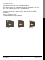
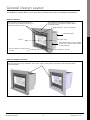
RINNAI
Reflection
Flame Fire Operation and Installation Manual
This appliance shall be installed in accordance with:
•Manufacturer’s Installation Instructions
•Local Gas Fitting Regulations
•NZS 5261 and Australian Installation Code AS5601
• Municipal Building Codes
•Any other local relevant statutory regulation
This product is only to be installed with an approved Rinnai flue system.
Installation and service must be performed by an authorised person.
INSTALLER: Please leave this manual with the customer after installation
OWNER: Please retain this manual for future reference
Rinnai New Zealand
Reflection: 03-08
Limited Warranty
Rinnai Reflection Flame Fires
Rinnai brings you peace of mind
with a 2 year minimum warranty.
TERMS AND CONDITIONS
3. Warranty claims may be invalid if not
accompanied by details of the installing or
1. During the 24 month period from date of
supervising gas fitter’s registration number and
purchase and subject to clauses 2 and 3 below,
the gas fitting certification number.
Rinnai New Zealand Limited (“Rinnai”) will, at
its own discretion, either replace or repair any
4. This warranty commences from the date of
defective product at no charge to the customer.
purchase. Proof of purchase is required at the
time of any warranty claim.
2. This warranty covers manufacturing defects
only. This warranty will not apply if (for
5. Servicing of the product is to be carried out by a
example) the product has been improperly
Rinnai authorised service centre.
installed or is otherwise installed contrary to
All Rinnai appliances meet or exceed the safety
manufacturer’s recommendations, has been
standards required by New Zealand gas and
damaged during or after installation, has not
electrical regulations. The company is constantly
been operated in accordance with operating
improving its products and as such specifications
instructions, or has been subjected to damage
are subject to change or variation without notice.
or abuse beyond that expected from conditions
of normal use.
Please keep these instructions in a safe place for future reference.
RECORD AND ATTACH YOUR PROOF OF PURCHASE BELOW:
Your Retailer:____________________________________________________
Name:_________________________________________________________
Address:_______________________________________________________
_______________________________________________________________
Telephone:( _______ ) ____________________________________________
Date of Purchase: ______ / ______ / _________
Rinnai New Zealand
Reflection: 03-08
Table of Contents
Limited Warranty.............................................................................................
Customer Information - Introduction..................................................................
Customer Information - Design Layout...............................................................
Customer Information - Safety..........................................................................
Customer Information - Installation...................................................................
Customer Information - ETR Operation...............................................................
Customer Information - Maintenance, Servicing and Repair...................................
Customer Information - Troubleshooting.............................................................
Customer Information - Error Codes .................................................................
2
4
5
6
7
9
13
14
14
Installer Information - Dimension Diagrams........................................................
Installer Information - Appliance Location...........................................................
Installer Information - Gas Supply and Connection...............................................
Installer Information - Flueing - General Guidelines..............................................
Installer Information - Flueing - Existing Fireplace...............................................
Installer Information - Flueing - Decorative Fireplace............................................
Installer Information - Installation Procedure......................................................
Installer Information - Testing Procedure............................................................
Installer Information - Installing the Frame, Trims and Dress Guard.......................
Installer Information - Installing the In-Wall Control Panel....................................
Installer Information - Commissioning Checklist..................................................
Installer Information - Wiring Diagram...............................................................
Customer Contacts..........................................................................................
16
17
18
19
20
21
23
27
28
29
30
31
36
WARNING
Improper installation, adjustment, alteration, service or maintenance
can cause property damage, personal injury or loss of life. For
assistance or additional information consult an authorised person or
Rinnai on 0800 RINNAI (0800 746 624).
Installation and service must be performed by an authorised person.
Rinnai New Zealand
Reflection: 03-08
Introduction
Congratulations on the purchase of your Rinnai Reflection Flame Fire.
Rinnai has been supporting New Zealand for over 30 years with quality appliances, and we’re
proud to have our products used everyday by many New Zealanders.
Rinnai Reflection...a reflection of inspired design, from an initial pencil sketch to ingeniously
designed, precision-engineered working models. The result is a New Zealand-made fire
that combines unrivalled energy efficiency with world-leading aesthetics and ergonomic
considerations.
Available in three designer models:
• Advance (best suited to masonry installations)
• Amplify (best suited to floor mounted false chimney installations)
• Elevate (best suited to up-wall false chimney installations)
Advance
Rinnai New Zealand
Amplify
Elevate
Reflection: 03-08
General Design Layout
The Reflection models differ only in the colour of frame surround and installation application.
Reflection Advance
Extruded aluminium frame available in two
colour options; Galaxy Black and Dark Bronze
(interchangeable)
Black Trim Kit, stainless steel option can
be purchased as an additional accessory to
customise the look of the fire
Black Grill Plate - warm air discharge
Reflection Engine
Log Set
Flat Glass Front
Extruded aluminium spacer available
in two colour options; Galaxy Black
and Dark Bronze
Receiver Window, remote control
receiver.
Black Grill Plate - air inlet
Reflection Amplify and Elevate
Extruded aluminium frame available in three colour options; Galaxy Black, Dark Bronze and Champagne Silver
(interchangeable)
Rinnai New Zealand
Reflection: 03-08
Safety
Do not restrict the warm
air discharge by placing
articles in front of the
appliance.
This appliance
must not be used
for any purpose
other than
heating.
Do not spray aerosols
whilst the appliance is
operating. Most aerosols
contain butane gas, which
can be a fire hazard if
used near the appliance
when it is in use.
Young children
should be
supervised at
all times. Hand
or body contact
with the heater
must be avoided.
Do not sleep directly
in front of the
appliance.
Do not allow
anyone to sit
on or lean
against the
appliance.
Do not allow anyone to
post articles through into
the heater.
Do not allow
curtains or other
flammable or
combustible
materials to come
into contact with
appliance.
Do not unplug the appliance while it is
in operation.
Unplugging the
appliance will
switch it off and
will reset the
appliance to its
default settings.
Some floorings will react
to heat. Therefore it is
recommended that a mat
be placed in front of the
appliance when it is in
operation.
When the appliance is
operated for the first
time or after long periods
of non-use a slight odour
may be emitted. This is
normal, however if odours
persist switch off the
appliance and contact a Rinnai Service Centre.
A dedicated
230~240V 10
Amp power point
must be used with this appliance. Do not
use power boards or double adaptors to
operate this appliance.
Do not place articles on or against this appliance. Do not use or store flammable materials near this appliance. Do not
spray aerosols in the vicinity of this appliance whilst in operation.
Rinnai New Zealand
Reflection: 03-08
Installation
Unpacking the Appliance and Associated Accessories
Unpack the appliance and check for damage. If damaged contact your supplier for advice. Do
not install a damaged appliance.
Before installing, check the label for correct gas type and that you
have all the components you need, refer checklist on page 23).
Gas type label
is displayed on
the appliance
Before using this appliance, please read this manual to ensure correct use. Failure to follow
these instructions could cause a malfunction of the appliance. This could result in death,
serious bodily injury and/or property damage. Failure to follow these instructions may also
void your fire insurance and/or warranty.
Compliance with
Local Regulations
The appliance must be installed in accordance with local gas and
electrical authority regulations.
Power Cord
Appliance must not be located below a power socket outlet. Local gas
and electrical authorities will be able to advise on local regulations. If the
supply cord is damaged or requires replacing, it must be replaced by an
authorised person. This must be a genuine replacement part available
from Rinnai.
Gas Consumption
30-11MJ/h (high to low)
Ventilation
Ensure that the area in which the appliance is installed has adequate
ventilation. This ventilation must be provided as per NZS 5261:2003
2.6.6.
Gas Cylinder
Do not connect to an LPG/Propane gas cylinder indoors.
Floor Protection
Heat emanating from the front of this fire may over time affect the
appearance of some materials used for flooring such as carpet, vinyl,
cork or timber. This may be amplified if the air in the room contains
cooking vapours or cigarette smoke. To avoid this occurring, it is
recommended that a mat be placed in front of the appliance.
Supervision
Required
The appliance is not intended for use by young children or infirm persons
without supervision. Young children should be supervised to ensure they
do not play with the appliance.
Painting and Dusty
Environments
Do not operate/install this appliance in places where painting is taking
place, or in places such as hair dressing salons, where there may be a lot
of dust and ‘fluff’, and where aerosols are used.
Flueing
A gas appliance must not be connected to a chimney flue serving as a
separate solid-fuel burning appliance.
For installations into new (decorative) fireplaces a Rinnai Zero Clearance
Box and Zero Clearance Flue Kit is required. Failure to meet this criteria
will void any product warranty.
For existing masonry installations, to ensure adequate draw of the
appliance, Rinnai strongly recommends the use of a Rinnai Flexiliner Flue
system. Failure to meet this criteria may result in an unsafe situation.
Installation without a flexiliner flue is permissible as long as the chimney
is checked for soundness and ability to achieve a good draw.
Rinnai New Zealand
Reflection: 03-08
Installation
Clearances
The appliance must not be installed where curtains or other combustible materials could come
into contact with it. In some cases, curtains may need restraining.
300mm
300mm
300mm
10
00
mm
Mantles, Surrounds and Hearths
Mantles and surrounds can be added to compliment design providing they conform to the
clearances below.
maxim
um d
epth
= 15
0mm
(at 2
00mm
)
200
mm
30
0m
m
300
mm
Mantles
Hearths
•
Minimum clearance of 200mm above the fire and a maximum of
150mm at this height
•
For additional overhang, 100mm of vertical clearance is required for
every 50mm of added depth, i.e. a 200mm mantle requires 300mm of
vertical clearance
A hearth is not necessary but can be used for decorative purposes or
protection of sensitive flooring materials if required. If used the bottom
of the appliance must be level with the top of the hearth so there is a
continuous level.
Rinnai New Zealand
Reflection: 03-08
ETR Operation
Control Panel Layout
Lock
Indicates lock function
Flame
High heat setting, fan on low speed, also overrides thermostat
AM/PM Time/Temperature Display
Shows either the time of day, room and set temperatures or
coded error messages
Clock Adjustment and Timer
Indicators
Indicates that clock or dual timer programme is being set
Override
Temporarily changes operation from ON to OFF or OFF to ON,
until next programmed setting is reached
Timer 1 and Timer 2
Indicates that Timer 1 or Timer 2 has been selected to operate
Temperature / Time Adjustment
Increases or decreases the temperature setting as well as
changing hours or minutes
AUTO OFF
When ON, thermostat turns heat down to OFF. When OFF,
thermostat turns heat down to low (prevents overheating in
small rooms)
ON/OFF
Main switch for turning ON / OFF
Turning On
Press the ON / OFF button to operate the heater. The ON indicator will glow green. The spark
generator will be heard before the burner ignites and the ON indicator glows red, indicating
that the burner is alight. The fan will come on automatically after four minutes after which
warm air can be felt coming from the top grill.
Note: If the heater does not ignite on initial use, this may be due to air remaining in the gas supply line. The
spark generator will only continue for 15 seconds. After this it will be necessary to press the ON / OFF button
OFF, then ON again.
Turning Off
Press the ON / OFF button to switch off the heater. The ON indicator will go out. The fan will
continue to operate for several minutes after the burner has gone out in order to cool the
appliance. Do not unplug the appliance while the fan is running.
Room Temperature Adjustment
The room temperature and pre-set temperatures can only be displayed and adjusted when the
heater is running.
Press the
button to increase the temperature setting or
temperature setting.
Rinnai New Zealand
button to decrease the
Reflection: 03-08
ETR Operation
Lock
The ‘Lock’ function will help prevent accidental operation and small children from altering the
controls. To operate press the ‘Lock’ button. The function is activated immediately and the
‘Lock’ indicator will glow. To deactivate press the ‘Lock’ button for three seconds and the ‘Lock’
indicator will go out.
During normal operation the ‘Lock’ may be activated and all the controls, other than the OFF switch, will be
locked. Deactivating the ‘Lock’ releases the controls. If the ‘Lock’ is activated whilst the heater is turned off,
then all functions will be locked. If the heater is turned off while the ‘Lock’ is activated, it cannot be turned on
again until the ‘Lock’ is deactivated.
Flame
To operate press the ‘Flame’ button. This function will automatically override the thermostat
and set the heater to a default high heat setting for full visual flame effect.
Auto Off
The ‘AUTO OFF’ function is an energy saving feature designed to control the room temperature
economically. If the room temperature continues to rise when the heater is thermostatically
turned down to its lowest setting the front burner will turn off leaving only the pilot flame
operating. When the room temperature requires further heating the heater will automatically
re-ignite to warm the room. This feature also prevents overheating in small rooms.
Override
This function is intended to be used to manually override the current operation of the heater
when the heater is in ‘Timer’ mode.
For example: if the heater is in standby mode (i.e. between the finishing and starting timer of
a timer operation), and the ‘Override’ button is selected, then the heater will begin to operate
and heat the room.
To operate press the ‘Override’ button, the ‘Override’ indicator will flash. To manually
deactivate press the ‘Override’ button again. The ‘Override’ indicator will go out, and the
heater will return to standby mode.
The heater will continue to operate in ‘Override’ until the ‘Override’ button is pressed again, or one of the
timers takes over the operation of the appliance. This means that the ‘Override’ mode will automatically drop
out if a programmed starting time is reached. The appliance will then return to operating at times programmed
into the ‘Timer(s)’.
Remote Control
The remote control will not turn heaters on if ‘Timer(s)’ have been set. To manually operate
when ‘Timer(s)’ are not selected, press the ‘ON’ or ‘OFF’ button. To alter the temperature
when the heater is operating, press the
or
buttons.
Rinnai New Zealand
10
Reflection: 03-08
ETR Operation
Remote Control continued
Important points:
• Some fluorescent lights may interfere with the transmission of remote control signals,
changing the position from which you are operating the remote may help
•
Avoid dropping the remote or getting it wet
•
Remote control works within five metres of the receiver from the heater
•
Remove battery if control is not going to be used for a long period, this will help avoid
damage from leaking batteries.
If the ‘Timer(s)’ have been selected, and the heater is in standby mode, and the ‘OFF’ button on the remote
control is pressed, the ‘Timer(s)’ will be deactivated.
Batteries are supplied with the remote when ordered with the fire. If purchasing the remote as an additional
accessory batteries are not included.
Setting the Clock
Example, setting the clock to 10:35am
1. Press the ‘Set Times’ button once, the ‘Clock’ indicator will flash
2. Press and hold the
button; the minutes will begin to change first, then the time will
change by whole hours
3. Release the button when the AM 10:00 shows on the digital display. Confirm that you have
selected ‘AM’, a small indicator on the left hand side of the digital display indicates the ‘AM’
setting.
4. Press and hold down the
go past ‘AM’ then the
button again, release the button when AM 10:35 shows. If you
button can be used to change the settings in reverse.
5. Press the ‘Set Timer’ button five times to lock in and complete setting the time. The ‘Clock’
and ‘Timer’ indicators will go out. A small indicator on the digital display will flash to show
that the clock is operating.
When the appliance is plugged in or after a power failure, the digital display will show --:-Programming the ON / OFF Timers
Before programming the Timers you must ensure that the clock has been set to the correct
time.
Example, ‘Timer 1’ to heat the room by 7:10am and finish at 9:00am
1. Press the ‘Set Times’ button twice, the digital display will show AM 6:00, ‘Timer 1’ indicator
will flash
2. Press the
button until AM 7:00 appears, release the button, then press it again until AM
7:10 appears (press the
button if you go past AM 7:10)
3. Press the ‘Set Times’ button again, the ‘Timer 1’ off indicator will flash. Press the
until AM 9:00 appears (press the
button if you go past AM 9:00)
button
4. Press the ‘Set Times’ button three times to lock in the program time, a small indicator on
the digital display will flash to show that the display has returned to the clock.
‘Timer 2’ is programmed in the same way. Remember to ensure that the ‘Timer 2’ indicator is flashing when
you program in the desired setting. The timers can be programmed to operate for any two periods within
twenty four hours.
Rinnai New Zealand
11
Reflection: 03-08
ETR Operation
Operating the Timers
Before operating the ‘Timer(s)’, the clock time must be correct and a start and finish time
must be programmed (see previous page). This heater does not commence operation at
the programmed start time, as it attempts to heat the room by the programmed start time
(refer Preheat section below).
To select the ‘Timer(s)’ to commence heating:
1. Check the time shown on the digital display is correct
2. Check the ‘ON’ and ‘OFF’ times for both timers if necessary
3. Press the ‘ON/OFF’ button to operate the heater, the ‘ON’ indicator will glow green and
the heater will begin to operate
4. Select the desired temperature setting
5. Press the ‘Timer 1’ and/or ‘Timer 2’ button(s). The timer indicators will glow and the
heater will remain in standby until one hour prior to the time programmed. When this
time is reached, the ‘Timer’ indicator will flash and the heater will operate. The ‘ON’
indicator glows red when the heater commences operation.
Set and Forget Operation
The heater can be operated to alternate between timers automatically during cold weather
by selecting ‘Timer 1’ and ‘Timer 2’ together. Both timer indicators will glow. The appliance
will remain on standby at intervals between the programmed start and finish times of each
timer. While the heater is operating during programmed intervals the timer indicator will
flash.
What does all this mean...
You can program the heater to turn on in the morning when you wake up and turn off when
you leave and also again in the evening when you get home. The set and forget operation
combined with the preheat functionality means you can wake up and come home to warm
areas in the house.
If there is a power failure, the system memory will retain the timer programs, and the clock will stop at the
time the power goes off. The clock will start again when the power comes back on, but the time will be slow by
the duration of the power failure. To set the clock to the correct time after the power has come back on, follow
the instructions on previous page.
Preheat
This function operates automatically in conjunction with either of the timers. When a timer
is selected, the heater may turn on anywhere within an hour prior to the programmed
start time of the timer. The preheat function will attempt to preheat the room by the
programmed ‘ON’ time.
This function is called the preheat due to the way it operates. The room temperature is
sensed one hour before the programmed time of either timer. The temperature differential
at the time of sensing the room governs how long before the programmed ‘ON’ time the
mircocomputer will operate the heater and ignite the burner.
Rinnai New Zealand
12
Reflection: 03-08
Maintenance, Servicing and Repair
Your heater needs very little maintenance, however the following information will help you
keep it looking good and working efficiently.
•
•
Unplug electrical cord before cleaning
DO NOT USE SOLVENTS. All parts of the heater and remote control can be cleaned using
a soft, damp cloth and mild detergent. Do not attempt to clean the heater while the
appliance is hot or operating.
Visual Inspection of Flame - Get To Know Your Flame Pattern
Each Rinnai Flame Fire has a distinct flame pattern. This should look the same every time you
start your fire, after an initial warm up period of approximately 20 minutes.
Abnormal flame performance and or pattern can indicate a problem with your fire, such as a
blocked flue or gas injectors. There are some warning signs that could indicate a problem.
•
•
•
Unusual smell from the appliance, this could indicate a blocked flue
Continued difficulty or delay in establishing a flame
Flame appears either very short or very long
Normal
•
•
•
Abnormal
Flame only burns part way across the burner
Artificial logs or burn media have shifted from when the fire was first installed
Soot building up on the inside of the glass door
During installation there will be an initial burning in period where some smoke and smell may
be experienced. This is a normal part of the operation but should be done in a well ventilated
room until these dissipate.
If any of the above signs occur, please call Rinnai to discuss.
Servicing and Repair
Rinnai has a service and spare parts network with personnel who are fully trained and
equipped to give the best service on your Rinnai appliance.
If your appliance needs servicing, please call 0800 RINNAI (0800 746 624) and select option 1
for a Service Centre in your area.
For reliable operation Rinnai Flame Fires should be serviced every two years (including
inspection of the flue system). If they are in a particularly dusty environment or subject to
excess lint, for example dog hair or where there are newly laid carpets then annual servicing
would be beneficial.
Regular servicing is not covered by the Rinnai warranty.
Do not attempt to carry out any service work other than that mentioned in the troubleshooting
pages. If you have any other faults or problems, please refer to your installer or call Rinnai on
0800 RINNAI (0800 746 624).
Rinnai New Zealand
13
Reflection: 03-08
Troubleshooting and Error Codes
Symptom
Cause
Solution
Burner will not light
•
No power present
Ensure power cord is plugged in and turned on
•
No gas present
Ensure gas supply is turned on
•
Power cut
Re-ignite after power is restored
•
Air in gas pipe
Purge air (installer to do)
•
Ignition failure
Repeat lighting procedure
Smell of gas
•
Leaking gas
Turn gas off at meter and call Installer
Fan not working
•
Heat switch not activated
Allow heater to run on HIGH for 15mins
Small soot deposit
•
Normal operation
No action required
Severe soot deposit
forming on glass or logs
•
Inadequate flue system,
log misalignment or
incorrect gas pressure
Call Installer
Condensation on glass
•
Normal operation
Allow heater to warm-up
Streaky lines on glass
•
Normal operation
Clean glass
Digital error message
on control panel
•
Electronic fault detected
Refer error codes
Safety Device
The appliance is fitted with an overheat safety switch. Under overheating conditions this switch
will shut off the appliance. If the appliance shuts off repeatedly servicing may be required.
Error Codes
Error Code
Probable Cause
Comments
11
•
Ignition failure
Check gas is turned on. Service call if repeated.
12
•
Flame failure
Check gas is turned on. Service call if repeated.
14
•
Overheat
Service call
16
•
Room overheat
Lower room temperature to less than 40oC
31
•
Room temperature sensor faulty
Service call
32
•
Room temperature sensor faulty
Service call
33
•
Overheat temperature sensor faulty
Service call
70
•
Faulty ON/OFF switch
Service call
72
•
Faulty flame rod
Service call
73
•
Communication error
Turn heater OFF, then ON again
99
•
Flue blocked
Turn on to low for 20mins to allow the flue to
warm up then turn up higher. Service call if
problem persists.
--:--
•
Power failure
Turn heater OFF, then ON again
In all cases, you can clear the error message by turning the heater OFF, then ON again. If the
error message still remains, please contact your nearest service contact and arrange for a
service call.
Rinnai New Zealand
14
Reflection: 03-08
Installer
Information
Rinnai New Zealand
15
Reflection: 03-08
Dimension Diagrams
All measurements are in mm.
Advance
30
860
100
589
Advance
Spacer
100mm
65
700
580
500
100
Amplify
860
30
589
750
65
580
500
62
50
62
Elevate
860
30
589
65
580
805
500
110
Rinnai New Zealand
16
Reflection: 03-08
Appliance Location
General
When positioning the unit the main points governing location are flueing and warm air
distribution.
This heater must not be installed where curtains or other combustible materials could come
into contact with the appliance. In some cases curtains may need restraining.
Enclosure Requirements
The heater must be positioned on a flat and level surface that allows free movement of the
appliance.
•
Masonry Installations, use a slurry of sand and cement to level base as required
•
Decorative Fireplace, if the heater is elevated the Zero Clearance Box needs to be
supported, either construct a base using board with supporting joists as shown or support
with the frame itself
supporting joists
Enclosure Dimensions
MASONRY INSTALLATION
DECORATIVE FIREPLACE
W-Width
590-790mm
700-720mm
H-Height
585mm
735mm
D-Depth
410mm
600mm
All dimensions provided are critical to the installation of this appliance
and must be adhered to.
Elevate
Installations
The Reflection Elevate is designed for up-wall decorative installations and has
a frame of 4 sides. To ensure you get the desired look or if floor mounting,
remember to allow for these frame dimensions when determining positioning
of the enclosure to ensure adequate clearance.
A functional height is 400mm from the floor to the bottom of the Zero
Clearance Box is recommended. When integrating a floating hearth, this
clearance can be stretched to 600mm. The Reflection range has a top air
discharge so this needs to be factored when installing.
Rinnai New Zealand
17
Reflection: 03-08
Gas Supply and Connection
Pipe Sizing
Gas pipe sizing must consider the gas input to this appliance as well as
other appliances in the premises. The gas meter and regulator must be
specified for the total gas rate. An approved sizing chart as the one in NZS
5261 should be used.
Purging Supply of All foreign materials such as filings must be purged from the gas supply, as
Air and Debris
they may cause the gas control to malfunction.
Reflection Gas
Connection
The gas supply terminates inside the heater and enters the appliance from
the rear. To ensure correct positioning, terminate the gas supply so that it
is approximately 80mm in from the front face of the enclosure opening. As
this is a flare connection, sealant is not recommended.
RH
Rear View
If using a zero clearance box, this 60mm
measurement is taken from the spacer
Masonry
Fireplaces and
Copper
Rinnai New Zealand
Brick work can be alkaline which can be corrosive to copper. Gas fitters
often wrap tape around the copper pipe coming into contact with the brick
work.
18
Reflection: 03-08
Flueing - General Guidelines
Every appliance requires a flue system that will draw effectively and clear flue products safely
under all potential wind and climatic conditions.
It is the responsibility of the installer to ensure that the appliance is provided with an effective
flue. Some guidelines to assist with flue design for the Reflection is listed below. These must
be read and modified as necessary with reference to the particular installation.
Flue Terminal
Locations
Must be compliant with ‘Clearances Required for Flue Terminals’ from NZS
5261:2003
Minimum Flue
Length
This is required for adequate draw and prevents spill-back of combustion
products which can cause safety sensors to shut down the fire.
• 3.6m vertical
• 1.2m of vertical flue is required before any bends or offsets
Maximum Flue
Length
Rinnai recommend a maximum flue height of 8m.
Flue Systems
For new fireplace installations a Rinnai Zero Clearance Box and Flue kit is a
mandatory requirement to meet warranty conditions.
For masonry installations, to ensure adequate draw, Rinnai strongly
recommends the use of a Rinnai Flexiliner Flue System. Failure to meet this
installation criteria may result in an unsafe situation. Installation without a
flexiliner flue is permissible as long as the chimney has been checked for
soundness and ability to achieve a good draw.
Shared Flues
Gas appliances must not be connected to a chimney or flue serving a
separate solid fuel burning appliance.
Flue Cowl
Clearance
To ensure products of combustion are cleared, adequate clearance from the
building is required. The following guideline is recommended.
Flue cowl should have a 500mm clearance from any part of the building.
This also applies to steeped and pitched roofs which should be 500mm clear
of the ridge line as displayed below.
3.6m minimum
8m maximum
500mm
Rinnai New Zealand
19
3.6m minimum
8m maximum
Lesser clearances may provide perfectly adequate flue systems depending
on the installation. Minimum clearances are shown in NZS 5261.
500mm
Reflection: 03-08
Flueing - Existing Fireplace
Check
Dimensions of
Opening
Check Flueway
Refer page 17 and if necessary bring
them to the required dimensions.
Also check chimney height as
inadequate height can effect product
performance. Some installations may
require the chimney height to be
extended to reduce down drafts.
Ensure there are no obstructions.
Provide a firm, flat and sealed base.
Sealed means no holes or openings in
the fireplace. If heater is not properly
supported noise and vibration may
result.
Chimney Cowl
Chimney
Plate
Flexible
Chimney
Liner
Install Flexiliner Ensure a minimum vertical rise of
Flue System
1.2m before any change of direction.
Avoid sharp bends as this will restrict
the chimneys ability to draw.
Installation without a flexiliner flue is
permissible as long as the chimney
has been checked for soundness and
ability to achieve a good draw. Some
criteria for checking soundness is
listed below.
•
Rinnai New Zealand
All loose/broken bricks must be
replaced or repaired ensuring the
chimney is of sound construction
and does not leak
Flue and
Appliance
Adaptor
Reflection
Fire
•
Chimney must be swept clean and
free from soot and creosote that
may have built up if previously
used for a solid fuel fire
•
Any damper plate must be fixed in the open position or removed
•
Any under-floor air supply to the fireplace must be completely sealed
off to prevent secondary air draw
•
An approved chimney cap and cowl must be installed. If there is an
existing cap it must be free of defects/deterioration and repaired/
replaced
20
Reflection: 03-08
Flueing - Decorative Fireplace
Overview of installation steps for a decorative fireplace
Flat wall
Construct
frame
Install Zero
Clearance Box
Drop in Flue
Plaster and
Paint
Install
appliance
For installations into decorative fireplaces a Rinnai Zero Clearance Box and Zero Clearance Flue
Kit is required. Failure to meet this installation criteria will void any product warranty.
We have developed a simple overview as to the steps and trades involved. Installing the
fire last minimises building debris/dust entering the fire which is common when building/
renovating.
Builder
1. Construct frame
2.
Assemble and
install Zero
Clearance Box
Construct Frame
and Install Zero
Clearance Box
Gas fitter
Install flue
Electrician
Install electrical
connection
Builder
Gib/line chimney
breast
Gas fitter
Install fire
Refer enclosure dimensions on page 17. Assemble and install Zero
Clearance Box. Installation needs to be on a level base. If this is not
done the appliance may twist and be damaged and will void any product
warranty.
The Reflection Zero Clearance Box flanges sit outside the lining. This
needs to be taken into account when calculating the depth dimension. The
600mm currently stated does allow for this.
Zero Clearance Box flanges sit
OUTSIDE the wall lining
Install the Flue
and Complete
Electrical
Connection
The flue should be self-supporting.
This is usually done at the framing
stage with flue supports (x2) provided
in flue kit which act as a bracket.
These are riveted to the flue. Please
note twin-skin flue requires a 25mm
clearance from combustibles.
Electrical cord is not fire rated and should not come into contact with the
fire. An electrical isolation switch is also required so positioning of this
switch needs to be factored when assessing where to install the unit.
Rinnai New Zealand
21
Reflection: 03-08
Flueing - Decorative Fireplace
Outline of Flueing Components (flue supports and flue adaptor not shown)
Clamping
Spacer
Flue Cowl
Sealing Collar
(not supplied)
Twin-Skin Flue
(requires 25mm clearance
from combustibles)
Outer Heat Shield Pipe
(length 1.2m)
Stainless Inner Flue Pipe
(length 1.2m, diam.
100mm)
Clamp Sleeve
Flame Fire
The inner flue should penetrate the box by
50mm. This is to ensure:
Zero Clearance Box
Rinnai New Zealand
22
•
Any residual heat in the box is ducted
away via the outer flue
•
When the fire is installed the clamp sleeve
can be lowered to connect the fire spigot
to the flue
Reflection: 03-08
Installation Procedure
Unpacking the Appliance and Associated Accessories
CHECKLIST
1.
Engine (logset inside chamber)
2.
Trim Kit (black provided as standard)
Supplied with engine
3.
Frame
Supplied separately
4.
Flexi-pipe gas connection
Supplied with engine
5.
Seal Strip, Advance only (for sealing appliance to enclosure)
Supplied with spacer
6.
Operation and Installation Instructions
Supplied with engine
7.
Remote Control (battery included)
Supplied with engine
8.
In-wall Control Panel complete with 2m cable (typically
supplied with Elevate and Amplify, provided with Advance if
spacer is not ordered)
Supplied separately
9.
Spacer, only for Advance models (ETR contains control panel)
Supplied separately
10.
Rinnai Zero Clearance Box and Zero Clearance Flue Kit
(Decorative Installations only)
Supplied separately
11.
Rinnai Flexiliner Flue Kit (Masonry Installations only)
Supplied separately
Optional
12.
Dress Guard
Supplied separately
13.
Stainless Steel Trims
Supplied separately
14.
8m Extension Cable
Supplied separately
Check for damage. If damage has occurred, contact your supplier for advice. Before
installation, check it is labelled for the correct gas type.
Remove the heater body assembly from the carton and position in front of the enclosure.
Rinnai New Zealand
23
Reflection: 03-08
Installation Procedure
Preparation
Remove Glass
Retainers
Place the appliance on a flat surface. Remove screws from the top and
lower glass retainers and lift off glass. This makes it easier to maneuver
the fire into the cavity.
Remove Logset
Carefully remove from the heater and place in a safer location until
required.
Check Flexi-Pipe
Connection
Make sure that the gas flare fitting and gas supply pipe are clean and free
of damage and fit together ready for fitting.
Electrical Connection
This appliance has a power cord with a three pin plug supplied. The power cord passes through
the insulating bush in the lower right hand side of the rear panel and must be plugged into a
230-240V, 10A earthed power point.
The power point must not be above the unit. The electric isolation switch must be accessible
after the appliance has been installed.
If using a zero clearance box, there is a knock out for the electrical connection with an edge
protector supplied. This needs to be cut and fitted.
Advance Masonry Electrical cord is not fire rated. Do not thread out of the back of the fire as
Installations
there is a risk the cord could come into contact with the back of the heater.
Electrical cable
In-Wall Control
Panel
Refer instructions on page 29.
Masonry Installations - Apply Sealing Strip
Apply sealing strip to rear of spacer/heater as shown. The strip is intended
to form a seal between the heater and the fireplace. If an adequate seal
cannot be formed with this strip another means of sealing must be used (non
combustible insulation) between the fireplace and the spacer/heater body.
Rinnai New Zealand
24
Reflection: 03-08
Installation Procedure
Slide Heater into Fireplace
Remove Top and
Lower Trims
to Expose Gas
Connection
To do this remove the screws holding the trims in place. For the lower
trim exercise care when removing as you will need to remove the control
receiver board from the holder.
Gas connection
Attach Flexi-tube
to Gas Pipe
Slide Heater into
Position
Do this carefully without forcing, while feeding the stainless steel flexi-tube
through the supply access opening. Sometimes the connection can catch
on the back of the fire, if this occurs either use a long drill bit, thread into
the gas pipe from the front to pull through and/or remove the plates above
and below for easier access to the gas connection coming through.
Flue Protector
Plate
A spring loaded flue protector plate is fitted to prevent the entry of foreign
objects for a masonry chimney installation. If a flexiliner flue system is
not used the plate will fold down as the heater slides through the fireplace
opening.
Make sure that it is not restricted and returns to its normal position when
the heater is installed. If the fire has to be removed, the plate will pivot
backwards to allow the heater to slide clear.
When a flexiliner flue system or Zero Clearance Box is used, the flue
protector plate must be unscrewed and removed.
Once the heater is sitting flat secure via the pre-drilled holes in the heater
surround.
Secure Heater to
the Fireplace
If using a Zero Clearance Box (ZCB), ensure inner holes of heater
mounting brackets align with the holes on the ZCB. The outer holes are for
fixing the frame to the ZCB.
For a masonry fixing, measure and
drill 4 holes in the fireplace and insert
wall plugs to secure backing plate and
spacer to the fireplace.
Rinnai New Zealand
25
Backing Plate sits
inside the back rim
of the spacer
Reflection: 03-08
Installation Procedure
Logset Installation
The logset assembly is made up of a main, top and right log (assembled as 1 piece) with 2
holes underneath for location onto the pins and inside the heater.
Remove Log
Packing and
Place Logset
Carefully remove log packaging and place
the logset onto the heater ensuring that the
locating pins enter the two locating holes of
the logset.
Place Granules
Gently place loose ember bed material
in front of the main log. Level it with a
pencil or screwdriver and remove excess
material.
Do not pour granules as dust particles
from plastic bag may block the burner
ports. The granules must be placed after
the logset is fitted. If the logset is to be
removed for any reason the granules must
be removed first.
Any material that prevents the logs sitting flat on the burner top can upset
the burning pattern and performance of the heater.
Replace Glass and Condition Logset
Replace and fit glass so that the join/gap in the glass seal is at the bottom. Take care not to
damage the seals.
When first lighting the heater, the logs need burning in. This can take approximately 2 hours
for the logs to achieve their full flame pattern and glow.
During the initial burning in period, some smoke and smell may be experienced. The heater
should be run on the high setting in a well ventilated room until these dissipate.
Rinnai New Zealand
26
Reflection: 03-08
Testing Procedure
Turn on gas supply and plug the unit into power supply.
Check Burner
Pressure
1. Remove test point screw and attach manometer to test point (right
hand side of gas valve)
2. Light heater, turn to high setting and check pressure (refer data plate).
You will need to wait 3 minutes before checking the pressure due to
PCB time delay to reach the high setting.
3. Adjust if necessary using regulator situated on the front of the gas
control. After checking pressure turn appliance off, remove manometer
and replace test point screw.
Check Ignition
Turn the heater on and off a few times to check ignition. When you are
satisfied that the heater is working correctly reassemble.
Check for Spillage Run heater for approximately 10 minutes to check for spillage, ensuring
products of combustion are cleared from the room. This must be done
using one of the following methods below.
It is the responsibility of the installer to check (under normal operating
conditions of the appliance) all flue gases are exhausted to the outside
atmosphere and that there is no spillage of combustion gases into the
room. Please refer to NZS 5261:2003.
Sample CO2 in this region only
Hold mirror in
this position
and check for
condensation
build up
Do NOT sample
for CO2 in the
hot air stream
blown by the
heater fan
Glass
Glass
Fan
After running the heater on high for
5 minutes, hold a mirror or reflective
surface over the top of the heater as
shown.
Look for any condensation build-up. Any
condensation on the mirror indicates the
heater is spilling CO2 into the room which
is not acceptable.
Fan
Before starting the heater use a CO2
capable gas analyser and record the
ambient CO2 percentage in the room.
Turn the heater on and run on high for 5
minutes, then check for CO2 emissions at
the top of the vent of the heater as shown.
The reading should be no more than the
initial ambient reading.
All burner aeration is factory preset and cannot be adjusted. If you are unable to
get the unit to operate correctly refer to Troubleshooting guide on page 14 before
contacting Rinnai.
Rinnai New Zealand
27
Reflection: 03-08
Installing the Frame, Trims and Dress Guard
Installing the Frame
Hang the top of the frame over the angled metal
lip of the fire body, frame should slot into place
as shown.
Installing the Trims
Attach trims to large circular magnets on either
side of the heater.
If installing the dress-guard ensure the holes on
the trims face inwards, these are used to secure
the guard to the heater.
Holes face
inwards if a
dress guard is
being fitted
If a dress-guard is not being used, the holes
should face in towards the frame so they can’t
be seen. To remove pry trims from the lower
edge closest to the inside of the fire.
Installing the Dress Guard
Position trims either side of the dress guard and using the four self tapping screws provided,
fasten the trims to the dress guard.
The top of the dress guard can be identified because it has a narrower section of frame, and
once assembled, the top of the frame should align with the top of the trim.
Position assembled dress guard onto the magnets, being careful not to scratch the glass front.
For cleaning and servicing, the dress guard can be removed by pulling it outward from the
bottom.
4 x self tapping
screws (included)
TOP
Narrow side of frame
Bottom
Top
Panel trim inner
dress guard
fixing holes
Rinnai New Zealand
BOTTOM
28
Reflection: 03-08
Installing the In-Wall Control Panel
Decide on
Suitable Location
The cable must be
routed back to the
heater, is 2m in length
(additional option of 8m
can also be purchased).
30mm clearance
from obstructions
Choose a location 30mm
clear of any obstruction
slots
inside the wall such
as framing, pipe work,
cables etc.
tension
clips
metal box
cable
opening
The control cable should not run alongside any other electrical cabling.
Mark a Template
Using Metal Box
Mark a horizontal line on the wall, using a spirit level
for the location of the bottom of the control panel.
Pull the metal box from the control panel assembly.
Using the back of the metal box as a template, align
the long side of the box with the horizontal line on the
wall, and trace around the back (not the flange) of the
metal box. This will be the minimum size of cut-out for
the control panel.
For plaster board cut along traced outline using a sharp blade first.
Cut Out Marked
Outline
Drill a 6mm hole in each corner of the outline. This will allow you to use a
keyhole saw to cut between the holes. Flange thickness of the metal box is
only 5mm so care is needed when cutting so as not to deviate outside the
traced line.
Insert Metal Box
Before inserting the metal box into the cut-out, pull the cable through the
opening provided in the lower part of the metal box. Insert the metal box
into the newly formed cut-out. Using the 4 tension clips provided, post
them through slots to retain the metal box in the plaster board cut-out.
A choice of slots is provided. You may choose to fit the box top and bottom
or left and tight. The slots are also punched at 2 alternate depths to allow
for both 10 and 13mm plaster board.
Connect
Everything
Together
Rinnai New Zealand
Connect the control panel to the extension cable. Feed the cable connection
back through the opening in the metal box, so that it is now located in the
wall cavity. The control panel can now be inserted into the metal box. A
click should be felt once properly located.
29
Reflection: 03-08
Commissioning Checklist
Complete the installation and commissioning checklist below and make sure this manual is left with the
customer. Explain to the customer about the use and care of the unit and understands the instructions
and operation of the appliance.
If operating without a dress guard please follow safety instructions to prevent the risk of injury from
burns. Young children and the infirm should be supervised at all times.
NO
YES
1. Appliance positioned in suitable location? (i.e. clearances, combustibles etc.)
2. Was a Rinnai approved flue system installed and is the flue
drawing effectively
3. Has specified gas pressures been checked and set?
4 Is the logset located correctly?
5. Have the granules been placed evenly on top of the burner,
free of dust and powder?
6. Has the appliance been test fired for correct operation?
7. Is the end-user fully aware of operating procedure?
Installer Details
Company name:______________________________________________________________
Installers name:______________________________________________________________
Address:____________________________________________________________________
________________________________________________________________________________
Phone:________________________________ Mobile:___________________________________
Permit number for installation:___________________________________________________
Signed: _______________________________ Date:________________________________
Rinnai New Zealand
30
Reflection: 03-08
Wiring Diagram (ETR)
Rinnai New Zealand
31
Reflection: 03-08
Customer Contacts
For more information about buying, living and servicing of Rinnai appliances call:
•
•
Consumers
Installers
0800 RINNAI (0800 746 624)
0800 TO RINNAI (0800 86 746 624)
Rinnai New Zealand Limited
105 Pavillion Drive
Airport Oaks
Mangere
Manukau
PO Box 53177
Auckland Airport
Manukau 2150
Phone:
Fax:
(09) 257 3800
(09) 257 3899
Email:
Website:
[email protected]
www.rinnai.co.nz
All Rinnai appliances meet or exceed the safety standards required by New Zealand gas and
electrical regulations.
Rinnai is constantly improving its products and as such specifications are subject to change or
variation without notice.
RINNAI
Reflection
Instructions
Part Number: 10957
Issue: C
Rinnai New Zealand
32
Reflection: 03-08