1
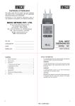
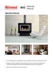
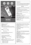
SAPPHIRE GAS LOG FLAME FIRE
Operation / Installation Manual
MODELS: RIB2311MN/A & RIB2311ML/A
This appliance shall be installed in accordance with:
• Manufacturer’s Installation Instructions
• Current AS/NZS 5601 AS/NZS 3000
• Local Regulations and Municipal Building Codes including local OH&S requirements
This appliance must be installed, maintained and removed by an Authorised Person.
For continued safety of this appliance it must be installed and maintained in
accordance with the manufacturers instructions.
All Rinnai gas products
are A.G.A. certified.
Congratulations on the purchase of your Rinnai Sapphire gas log flamefire.
We trust you will have many years of comfort and enjoyment from your appliance.
BEFORE PROCEEDING WITH THE OPERATION OR INSTALLATION OF YOUR NEW HEATER
PLEASE READ THIS MANUAL THOROUGHLY AND GAIN A FULL UNDERSTANDING OF THE
REQUIREMENTS, FEATURES AND OPERATION OF YOUR NEW APPLIANCE.
Rinnai Australia
2
RIB2311 Sapphire Operation & Installation Manual
TABLE OF CONTENTS - OPERATION
BEFORE YOU START .......................................................................................................................................... 4
INSTALLATION REQUIREMENTS ..................................................................................................................... 4
CERTIFICATION ................................................................................................................................................. 4
CARTON CONTENTS / ITEM CHECKLIST........................................................................................................ 4
INSTALLATION RECORD .................................................................................................................................... 6
SAFETY ................................................................................................................................................................. 7
SAFETY DEVICES.............................................................................................................................................. 9
ABOUT YOUR HEATER ..................................................................................................................................... 10
GENERAL DESCRIPTION................................................................................................................................ 10
DESIGN FEATURES......................................................................................................................................... 11
CONTROL PANEL OPERATION........................................................................................................................ 12
TO TURN YOUR HEATER ON ......................................................................................................................... 12
FLAME HEIGHT & FAN SPEED SETTINGS .................................................................................................... 12
TO TURN YOUR HEATER OFF ....................................................................................................................... 12
INTERRUPTION TO ELECTRICITY OR GAS SUPPLY DURING OPERATION.............................................. 12
RESTART PROCEDURE AFTER INTERRUPTION TO ELECTRICITY SUPPLY ........................................... 12
RESTART PROCEDURE AFTER INTERRUPTION TO GAS SUPPLY ........................................................... 12
REMOTE / THERMOSTATIC CONTROLLED OPERATION.............................................................................. 13
REMOTE CONTROLLER - BATTERY INSTALLATION ................................................................................... 13
REMOTE CONTROLLER - SYNCHRONISATION. .......................................................................................... 14
REMOTE CONTROLLER - MANUAL OPERATION ......................................................................................... 14
REMOTE CONTROLLER - AUTOMATIC OPERATION ................................................................................... 15
WIRELESS CONTROLLER / THERMOSTAT................................................................................................... 16
TO TURN YOUR HEATER ON WITH REMOTE / THERMOSTATIC CONTROL............................................. 18
MODES OF OPERATION ................................................................................................................................. 18
PROGRAMMING OF PROGRAM MODES....................................................................................................... 20
CARE AND MAINTENANCE............................................................................................................................... 22
SERVICE........................................................................................................................................................... 22
TROUBLE SHOOTING ..................................................................................................................................... 22
TROUBLE SHOOTING CHECKLIST ................................................................................................................ 23
ABNORMAL FLAME PATTERN........................................................................................................................ 23
TABLE OF CONTENTS - INSTALLATION......................................................................................................... 25
CONTACT INFORMATION ................................................................................................................................. 56
Rinnai Australia
3
RIB2311 Sapphire Operation & Installation Manual
BEFORE YOU START
INSTALLATION REQUIREMENTS
This heater must be installed by an authorised person. The installation must conform to local regulations.
The installation must also comply with the instructions supplied by Rinnai.
Service and removal must be carried out by an authorised person.
CERTIFICATION
The Rinnai Sapphire® has been certified by the Australian Gas Association.
The AGA Certification Number is shown on the appliance dataplate.
No parts or functions should be modified or permanently removed from the heater.
Please keep these instructions in a safe place for future reference.
CARTON CONTENTS / ITEM CHECKLIST
The components for Sapphire heater are supplied in separate cartons, the following tables list which components
are in each carton. Ensure that the components listed for the installation method being installed are present before
proceeding with the installation.
IMPORTANT
The Engine and Fascia are packed into two separate cartons and are required for all installation
types. Masonry installations may require a flexiliner flue to be installed, refer to “MASONRY FLUE
INSTALLATION” on page 33 for details.
A
A. Standard
Fascia
1
2
12
4
3
6
5
B. Classic
Fascia * 2
3
8
7
9
10
5
4
10
Carton Contents
Component Descriptions
* The Classic fascia / Mesh dress guard is suitable for Masonry and Zero Clearance - Inbuilt Installation
installations ONLY! It and can NOT be used on a Console or Plinth installation.
A
11
Engine
Fascia
Engine and Fascia - Masonry Installations (x2 Cartons)
1
Rinnai Sapphire Engine.
2
A. Fascia (Standard Model) / B. Fascia (Classic Model)*.
3
A. Glass dress guard (Standard Model) / B. Mesh dress guard (Classic Model)*.
4
Inner metal surround.
5
Artificial log set / burn media, Satchel burner granules (shipped inside engine).
6
Semi rigid stainless steel gas pipe with 5/8” connections (x1).
7
½” BSP - 5/8” UNF flared brass adaptors (x1).
8
½” BSP Flared nut (x1).
9
5/8” UNF Plug (x1).
10
Fascia attachment screws (2 x 8g black, pre-fitted in tabs of heater engine).
11
Adhesive backed foam sealing strip.
12
Operation and Installation manual.
Rinnai Australia
4
RIB2311 Sapphire Operation & Installation Manual
BEFORE YOU START
B 1a+b
C
6
4
2
A
3
D
1a+b
2
4
1
2
4
2
3
A
A
5
E
1a+b
3
6
3
F
8
7
7
7
6
5
6
5
1a+b
8
Note: Standard model fascia shown for illustrative purposes
B
See Engine and Fascia (Masonry Installations) contents on previous page.
1
Two piece Spigot Adapter
2
Spigot guide panel.
3
Spigot guide rails (x2).
4
Zero Clearance - Top panel.
5
Zero Clearance - Rear panel.
6
Zero Clearance - Left & Right side panels.
7
Base panel.
8
Packet assembly screws (x27), grommets (x2) and rivets (x2).
a
Top Half and
b
1
Two piece Spigot Adapter
2
Console Installation - Top panel.
3
Console Installation - Left side panel.
4
Console Installation - Right side panel.
5
Console Installation - Rear panel.
6
Console Installation - Pillar.
7
Packet assembly screws 35 x 8g and 7 x M5.
a
Top Half and
b
Spigot
Adaptor
Plinth Installation - Freestanding Installation (x3 Cartons)
See Engine and Fascia (Masonry Installations) contents on previous page.
1
Two piece Spigot Adapter
2
Plinth Installation - Top panel.
3
Plinth Installation - Left side panel.
4
Plinth Installation - Right side panel.
5
Plinth Installation - Rear panel.
6
Plinth Installation - Pillar assembly.
7
Plinth Installation - Base panel.
8
Packet assembly screws 35 x 8g (only 29 needed for installation) and 7 x M5.
a
Top Half and
b
Bottom Half.
Optional Wireless Remote / Thermostatic Control (x1 Carton)
1
Wireless remote/thermostatic control with wall mount.
2
AA batteries (x2).
3
Operating Instruction.
1
Remote
Thermostat
Bottom Half.
A
F
Plinth
Console Installation - Freestanding Installation (x3 Cartons)
See Engine and Fascia (Masonry Installations) contents on previous page.
E
Console
Bottom Half.
A
D
Fascia
Zero Clearance - Inbuilt Installation (x3 Cartons)
A
C
Engine
* The Classic fascia / Mesh dress guard is suitable for Masonry and Zero Clearance - Inbuilt Installation
installations ONLY! It and can NOT be used on a Console or Plinth installation.
Zero
Clearance
Box
Carton Contents
Component Descriptions
Optional Two Piece Spigot Adapter (x1 Carton)
Two piece Spigot Adapter
Rinnai Australia
a
Top Half,
b
Bottom Half and assembly screws (x4)
5
RIB2311 Sapphire Operation & Installation Manual
INSTALLATION RECORD
INSTALLERS / GAS FITTERS DETAILS
Installers Name:
____________________________________________________________________
Company Name:
____________________________________________________________________
Company Address: ____________________________________________________________________
____________________________________________________________________
____________________________________________________________________
Company Contact Details
Telephone:
____________________________________________________________________
Mobile Phone:
____________________________________________________________________
Certificate of Compliance / Certification Number: _____________________________________________
Authorised Persons - Licence Number: _____________________________________________________
Installers Signature: ____________________________________________________________________
Installation Date:
____________________________________________________________________
APPLIANCE DETAILS
Model Number:
____________________________________________________________________
Serial Number:
____________________________________________________________________
Installation Address: ____________________________________________________________________
____________________________________________________________________
____________________________________________________________________
____________________________________________________________________
THIS APPLIANCE MUST BE INSTALLED, SERVICED
AND REPAIRED BY AN AUTHORISED PERSON.
Rinnai Australia
6
RIB2311 Sapphire Operation & Installation Manual
SAFETY
WARNING
• Failure to comply with these instructions could result in a fire or explosion, which could cause
serious injury, death or property damage.
• Improper installation, adjustments, service or maintenance can cause serious injury, death or
property damage. Such work must be performed by an authorised person.
• The appliance must be installed in accordance with the local gas and electrical authority
regulations.
• Flue terminal must always vent directly to outdoors.
• DO NOT extend the flue vertically or horizontally in ways other than prescribed in the appliance
manufacturers’ installation instructions.
• For information on gas consumption, see data plate on the appliance.
• This appliance must not be installed where curtains or other combustible materials could come
into contact with it. In some cases curtains may need restraining.
• WARNING: This heater MUST NOT be used if either of the glass panels are damaged.
• When considering installation ensure minimum clearances as follows are adhered to:
10
mm
INBUILT MODELS
10
mm
40
0m
m
40
0m
m
FREE-STANDING MODELS
75mm
m
75
m
Note: Standard model
fascia shown fo r
illustrative purpose s
40
0m
m
m
00
40
0m
m
7
5
7
5
m
0
m
m
m
m
10
0
m
00
10
m
• Heat radiating from the front of this heater may over time affect the appearance of some materials
used for flooring such as carpet, vinyl, cork or timber. This effect may be amplified if the air in
the room contains cooking vapours or cigarette smoke. To avoid this possibility, it is
recommended that a mat or similar protective sheet be placed in front of the appliance, extending
at least 750 mm in front of the dress guard.
• This appliance is not intended for use by persons (including children) with reduced physical,
sensory or mental capabilities or lack of experience and knowledge, unless they have been given
supervision or instruction concerning use of the appliance by a person responsible for their
safety.
• The appliance is not intended for use by young children or infirm persons without supervision.
• Young Children must be supervised when in the vicinity of this heater while it is in operation.
• The Dress Guard MUST be fitted to this appliance to reduce the risk injury from serious burns
and no part of it should be permanently removed.
• For protection of young children or the infirm a secondary guard is required.
• If the supply cord is damaged or requires replacing, it must be replaced by the manufacturer or
the manufacturer's agent or similarly qualified person in order to avoid a hazard.
• The heater must not be located immediately below a power socket outlet.
• DO NOT connect to an LPG Gas cylinder indoors.
• A dedicated 240 V earthed 10 Amp power point must be used with this appliance.
• DO NOT modify this appliance. Modifying from original specifications may create a dangerous
situation and will void your warranty.
• Only the flue components specified by Rinnai must be used.
• Unpack the heater and check for damage. DO NOT INSTALL A DAMAGED HEATER. If the heater
is damaged, contact your supplier for advice.
• Before installing the heater, check the label for the correct gas type (refer rating plate, inside the
appliance).
• Refer to local gas authority for confirmation of the gas type if you are in doubt.
Rinnai Australia
7
RIB2311 Sapphire Operation & Installation Manual
SAFETY
Note: Standard model fascia shown for illustrative purposes
The appliance is not intended for use by young children or infirm persons without supervision.Young children
should always be supervised to ensure that they DO NOT play with the appliance.
DO NOT sit or lean against the heater.
DO NOT allow children or elderly persons to sleep in the warm air discharge from the heater.
Note: Standard model fascia shown for illustrative purposes
DO NOT post or allow children to post articles into the louvres of the heater.
DO NOT cover or place articles on this heater.
DO NOT place articles in front of the louvres.
Note: Standard model fascia shown for illustrative purposes
DO NOT operate / install this heater in areas where painting is taking place, or in places such as hairdressing
salons, where there may be fluff and dust, and where aerosols are used.
DO NOT place articles on or against this appliance.
DO NOT use or store flammable materials near this appliance. Keep flammable materials away from heater.
Combustible materials MUST NOT be placed where the heater could ignite them.
DO NOT spray aerosols in the vicinity of this appliance while it is in operation. Most aerosols contain flammable
substances which can be a heater hazard if used near this heater when it is in use.
Rinnai Australia
8
RIB2311 Sapphire Operation & Installation Manual
SAFETY
A dedicated 240V earthed 10 Amp power point must be used with this appliance.
DO NOT use power boards or double adaptors to operate this appliance. The heater MUST NOT be located below
a power socket-outlet.
DO NOT place containers of liquid on top of the heater. Water spillage can cause extensive damage to the
appliance and create an electrocution hazard.
DO NOT place articles on or against this appliance.
m
7
5
0
m
DO NOT CONNECT TO AN LPG GAS CYLINDER INDOORS.
Turn the heater ‘OFF’ after use.
DO NOT unplug the heater while it is in operation or while the fan is still cycling.
DO NOT remove the Dress Guard. The dress guard is fitted to this appliance to reduce the risk of fire or injury from
burns and no part of it should be permanently removed. For protection of children or the infirm, a secondary guard
is recommended.
Heat emanating from the front of the appliance may over time affect the appearance of some materials used for
flooring such as carpet, vinyl, cork or timber. This affect may be amplified if the air in the room contains cooking
vapours or cigarette smoke. To avoid this possibility, it is recommended that a mat be placed in front of the
appliance, extending at least 750 mm in front of the heater.
When the heater is operated for the first time or after long periods of non use a slight odour may be emitted, this is
normal. However if odours persist switch ‘OFF’ the appliance and contact Rinnai.
SAFETY DEVICES
Over Heat Switches: When the heater gets too hot during operation (for example when air outlet louvres are
blocked) these devices turn the gas off automatically and allow the heater to restart when cooled down.
Electrical Fuse: The electrical circuits are protected by a fuse.
Flame Failure Sensing System: This device automatically cuts off the gas supply to the heater in the event of a
flame failure.
Power Failure: In the event of a power failure or power cut, the gas valves will automatically close.
Rinnai Australia
9
RIB2311 Sapphire Operation & Installation Manual
ABOUT YOUR HEATER
GENERAL DESCRIPTION
Your Sapphire is a burning log effect, gas space heating appliance with natural draft combustion system, intended
for use with Natural Gas, Propane and ULPG. The Burning log effect is achieved using one single main burner with
strategically placed, 'life like', imitation logs and granules. Temperature control is achieved by pressing the up or
down marked arrows on the manual control switch or via a cordless wall mounted remote control thermostat / timer.
This heater has an electronic ignition with intermittent pilot. The pilot is only on when the heater is in operation.
Burner, logs and granules are contained in a glass fronted, sealed burner box.
Combustion air is drawn from the room. Combustion product is exhausted via the flue discharge vent when
installed in a masonry chimney or when installed in a zero clearance box or as a stand alone unit through a
100mmØ x 150mmØ twin skinned flue to the outside of the house.
This appliance is modular and primarily consists of an 'Engine' that is utilized in any of the 3 configuration types as
listed below.
1. Fireplace / Masonry installation - Engine:
The appliance is directly mounted into an existing masonry fire place or a non-combustible/masonry enclosure
that has a chimney. When installed correctly the appliance is a flush to wall mount.
2. Zero Clearance installation:
The Appliance is fitted within a sheet metal Zero Clearance Box Assembly that has been installed into a wall or
other suitable structure. Materials need not be non-combustible. When installed correctly the appliance is a
flush to wall mount.
3. Freestanding Plinth or Console appliance:
The appliance is housed in a decorative fabricated sheet metal box that is intended to be freestanding and not
inbuilt.
MASONRY
ZERO
CLEARANCE
Note: Standard model
fascia shown for
illustrative purposes
PLINTH
Rinnai Australia
CONSOLE
10
RIB2311 Sapphire Operation & Installation Manual
ABOUT YOUR HEATER
DESIGN FEATURES
1
4
5
a
b
c
d
2
3
6
1
7
5
7
4
8
2
3
6
7
7
1 Rinnai Sapphire Heater
2 Push button control panel
a ON / OFF (Standby) button
b Power / operation indicator
c Flame Up button
d Flame Down button
3 Glass dress guard (standard model) / Mesh dress guard (classic model)
4 Flame window - artificial log set and burn media
5 Warm air discharge vent
6 Return air vent
7 Alternative power cable outlet location on front panel can be left or right handed
8 Optional Radio Frequency (RF) combination remote / thermostatic control with wall mount.
Rinnai Australia
11
RIB2311 Sapphire Operation & Installation Manual
CONTROL PANEL OPERATION
TO TURN YOUR HEATER ON
BEFORE PROCEEDING ENSURE THE GAS AND ELECTRICITY ARE TURNED ON.
NOTE
When the heater is in the OFF condition (the power supply connected and switched ON but the
heater turned OFF) the Power Indicator will be extinguished, this is normal.
The 'Push Button Control Panel' is located at the
top left edge of the heater.
Step 1. Press ‘ON’/‘OFF’ button a once. The
electronic ignition sparker will be able to
be heard.
Step 2. The electronic ignition stops when the
pilot flame has been established, the
main burner then ignites off the pilot
and is automatically preset to Stage 7 High Flame. The blue LED Power
Indicator,
will be constantly
b
illuminated indicating heater is in
operation.
a
b
c
d
Step 3. Flame height may be adjusted after 1
minute of operation. To change the
burner and fan settings press c to
increase flame height and d to
decrease flame height.
FLAME HEIGHT & FAN SPEED SETTINGS
NOTE
The relationship between the flame
height and fan speed are preset and
can not be independently adjusted.
FLAME HEIGHT
FAN SPEED
1
2
3
4
5
6
7
HIGH LOW LOW LOW HIGH HIGH HIGH
TO TURN YOUR HEATER OFF
NOTE
When the heater is in the OFF/STANDBY condition (power supply connected and switched ON) the
blue LED Power Indicator will be extinguished. This is normal.
To turn the heater 'OFF' press the 'ON'/'OFF' Button a once. The blue LED Power Indicator b , will extinguish to
indicate that the appliance has returned to the in OFF condition.
INTERRUPTION TO ELECTRICITY OR GAS SUPPLY DURING OPERATION
Interruption to the power or gas supply will turn your heater off. Restart will be required This is a safety feature
designed to ensure that un-attended starts do not occur.
RESTART PROCEDURE AFTER INTERRUPTION TO ELECTRICITY SUPPLY
To restart your heater once power has been restored follow the steps for “TO TURN YOUR HEATER ON” above.
RESTART PROCEDURE AFTER INTERRUPTION TO GAS SUPPLY
The instant gas supply is interrupted the heater will attempt re-ignition for a period of 60 seconds.
If the heater has not re-lit after 60 seconds the gas control will go to 'Gas Lock-out'. The convection fan will remain
on for 4 minutes to cool the appliance.
To restart your heater once gas has been restored:
Step 1. Ensure gas supply has been re-established to heater.
Step 2. To re-set the gas control turn 'OFF' the heater by pressing 'ON/OFF' button a once.
Step 3. In rapid succession Press button a , 3 times. (Turn 'ON', then 'OFF', then 'ON' again), within a 5 second
period.
Rinnai Australia
12
RIB2311 Sapphire Operation & Installation Manual
REMOTE / THERMOSTATIC CONTROLLED OPERATION
For further enhanced comfort and convenience the Sapphire heater can be both remotely and thermostatically
controlled through the use of a wireless wall mountable controller / thermostat.
The wireless controller / thermostat is an optional extra available through your Rinnai stockist.
DISPLAY LAYOUT & FEATURES
1
Time of day with ‘AM’ or
‘PM’ display
Displays time of the day in hours and minutes, ‘AM’ or ‘PM’.
The time is displayed when the thermostat is ‘ON’ or ‘OFF’.
6
2
Day of the week
Displays the current day of the week.
The day is displayed when the thermostat is ‘ON’ or ‘OFF’.
17
3
Current Room temperature
display
Displays the current temperature.
The temperature range is 7°C - 32°C.
4
Setting Temperature
‘SET’ display
When the thermostat is ‘ON’, the programmed (set)
temperature will be displayed.
5
Transmit indicator
Indicates that the thermostat is transmitting to the receiver,
the symbol will appear on the LCD for 1 sec.
6
Battery Low indicator
Indicates when the battery power is below an acceptable
level.
7
Automatic mode indicator
Indicates if the thermostat is in automatic mode.
8
Program mode indicator
Indicates that the thermostat is in programming mode.
9
Manual mode indicator
Indicates if the thermostat is in manual mode.
10
Setting ‘UP’ Button
Increase hours, minutes, day or temperature.
11
‘OK’ Button
Accepts the current function and advances to the next
function.
12
‘PWR’ (Power) Button
Switches the thermostat ‘ON’ and ‘OFF’. To turn ‘ON’ press
and release the ‘PWR’ and ‘OK’ Buttons at the same time
this will turn the thermostat ‘ON’ to the most recently
programmed working mode.
13
‘A/M’ Button
Toggles between automatic, manual and flame mode.
14
‘T’ (Time) Button
Initiates time and day of the week programming (must press
and hold for 2 or more seconds when the thermostat is
‘OFF’).
15
Setting ‘DOWN’ Button
Decrease hours, minutes, day or temperature.
16
‘P’ (Program) Button
Initiates the programming mode (must press and hold for 2 or
more seconds when the thermostat is ‘OFF’).
17
Flame Indicator
Indicates the flame setting.
5
3
4
1
2
7
9
8
UP
A/M
T
OK
P
with
PWR
DOWN
BUTTON LAYOUT & FEATURES
10
11
UP
A/M
13
14
15
T
OK
DOWN
P
PWR
12
16
The Flame symbol graphically indicates which of the 7
graduated settings between Low and High flame when the
burner is on.
In AUTO or MANUAL temperature mode, if the burner is OFF
due to room temperature being reached the symbol will
modulate UP and DOWN. This is to indicate that the unit is
still ON even though there are no flames visible in the
appliance.
REMOTE CONTROLLER - BATTERY INSTALLATION
Carefully remove the battery compartment cover panel from the rear of your controller hand-set and
insert the two AA batteries supplied ensuring that '+' and '-' polarity is correct. After installing the
batteries your remote control will display an 'Initial Set-up Screen' with the current room temperature
in °C, a default time setting of
and the default day of the week set to ‘MO’ - Monday.
NOTE
When batteries are changed all settings other than synchronisation are lost and the
controller will revert back to the 'Initial set -up screen'.
Rinnai Australia
13
RIB2311 Sapphire Operation & Installation Manual
REMOTE / THERMOSTATIC CONTROLLED OPERATION
REMOTE CONTROLLER - SYNCHRONISATION.
NOTE
Before proceeding with synchronisation ensure that the gas and electricity are connected.
Synchronisation must be carried out when a new controller has been purchased. Two controllers
CAN NOT be used at the same time!
The heater will not respond the controller until synchronisation has been carried out.
Synchronisation of Controller & The Heater
Step 1).Turn the power off at the power point for a minimum of 30 seconds, synchronisation will not be
possible unless the minimum 30 seconds has been observed.
a
b
Step 2).Ensure the remote control is turned OFF, to turn OFF press and release the ‘PWR’ button once.
Step 3).Turn the power ON at the power point, the blue power operation indicator b on the push
button control panel will flash once. The controller can now be synchronised with the heater.
NOTE
Synchronisation MUST BE performed within 30 seconds of the power being turned ON, if more than
30 seconds has elapsed repeat steps 1 through 3.
Step 4).On the controller in quick succession press the following sequence of buttons: ‘P’ > ‘T’ > ‘T’ > ‘UP’
The LCD display will show ‘L/C’ (Learn Code) for 2 seconds then return to the normal ‘OFF’ state display.
The blue power operation indicator b on the push button control panel will flash once to indicate that
synchronisation has been accepted.
To restore factory default settings
With the thermostat ‘OFF’, press the following sequence of buttons ‘P’ > ‘T’ > ‘T’ > ‘DOWN’.
REMOTE CONTROLLER - MANUAL OPERATION
Turning ‘ON’
Step 1).Press ‘ON’/‘OFF’ button of the Push Button Control Panel a once the Power Indicator LED b , will
illuminate blue.
Step 2).Press both the ‘OK’ and ‘PWR’ buttons on the controller at the same time. Operational control is now
transferred to the controller, the heater operation is then dependant on the controller mode as follows:
In Manual Mode - Unless the set temperature is above that of the room temperature the heater will not
ignite and the power Indicator LED b will turn red to indicate that the heater is in Controller Standby
mode. Raising the set temperature above that of the room temperature will start heater operation and the
Power Indicator LED b , will change from red to blue.
Turning ‘OFF’
Step 1).To place heater into controller standby press the ‘PWR’ button once. The heater will go into ‘Standby’
mode and the power Indicator LED b will turn red.
Step 2).To turn the heater 'OFF' press the 'ON'/'OFF' Button a twice. The Power Indicator LED b , will be
extinguished to indicate that the appliance has returned to the OFF condition.
Changing the temperature
The Sapphire has temperature increments of 1° which can be changed using the ‘UP’ and ‘DOWN’ buttons.
The temperature control range is 7 - 32°C
Change between Celsius - °C and Fahrenheit - °F
The thermostat temperature display can be set to °C or °F. The default is °C.
With the controller ‘OFF’, press the following sequence of buttons: ‘P’ > ‘T’ > ‘T’ ‘A/M’ to toggle between °C or °F.
Change between manual, automatic and flame modes
Press and release the ‘A/M’ button.
The unit first lights the pilot and then after a short period switches to the ‘HIGH’ flame setting.
To turn ‘OFF’ press and release the ‘PWR’ button once.
Rinnai Australia
14
RIB2311 Sapphire Operation & Installation Manual
REMOTE / THERMOSTATIC CONTROLLED OPERATION
REMOTE CONTROLLER - AUTOMATIC OPERATION
Setting the Current Time and Day of the Week
STEP 1
STEP 2
STEP 3
10
UP
A/M
T
OK
UP
P
PWR
A/M
OK
T
DOWN
UP
P
PWR
A/M
T
DOWN
OK
P
PWR
DOWN
11
14
15
Step 1. With the controller ‘OFF’, press and hold the ‘T’ button
‘HOUR’ and ‘AM or PM’ will flash.
NOTE
14
for approximately 2 seconds. ‘TIME’,
If no buttons are pressed within 10 seconds the display will revert back to 'Initial Set-Up Screen'
retaining the last entered setting.
Step 2. To select the hour push the ‘UP’ button 10 or ‘DOWN’ button 15 until the desired hour is chosen, note
that AM or PM is chosen by cycling through the 12 hour range.
Step 3. Press the ‘OK’ button
will flash.
11
to enter the selected hour and AM or PM. ‘TIME’ + ‘MINUTES’ + ‘AM or PM’
STEP 5
STEP 4
STEP 6
STEP 7
10
10
UP
UP
A/M
T
OK
P
PWR
A/M
T
OK
UP
P
PWR
A/M
DOWN
DOWN
T
OK
UP
P
PWR
A/M
T
DOWN
11
OK
P
PWR
DOWN
11
15
15
Step 4. To select the minutes push the ‘UP’ button
chosen.
Step 5. Press the ‘OK’ button
will flash.
11
11
or ‘DOWN’ button
15
until the desired minutes are
to enter selected minutes, One of the days SU, MO, TU, WE, TH, FR or SA
Step 6. To select the hour push the ‘UP’ button
Step 7. Press the ‘OK’ button
10
10
or ‘DOWN’ button
15
until the desired day is chosen.
to enter the selected day and to complete time and day setup.
To adjust time for Daylight Saving time
To adjust time or to adjust for daylight savings follow Steps 1 and 2 then press ‘OK’ button
keep the minutes and the current day.
NOTE
11
, three times to
When changing batteri