1
Preface, Contents
Connections
1
Operating condition
2
To establish the system
3
Installation SINAUT MICRO SC
4
OPC Routing Software SINAUT
MICRO SC
5
SINAUT MICRO SC
configuration
6
PLC Library SINAUT MICRO
SC
7
PLC Library SINAUT MICRO
SC Flex Px
8
MD720-3 in OPC Mode
9
SIMATIC NET
SINAUT MICRO SC
System manual
Troubleshooting
Glossary
C79000-G8900-C210
Release 08/2008
10
Safety Guidelines
This manual contains notices you have to observe in order to ensure your personal safety, as well as to prevent
damage to property. The notices referring to your personal safety are highlighted in the manual by a safety alert
symbol, notices referring only to property damage have no safety alert symbol. These notices shown below are
graded according to the degree of danger.
!
!
!
Danger
indicates that death or severe personal injury will result if proper precautions are not taken
Warning
indicates that death or severe personal injury may result if proper precautions are not taken.
Caution
with a safety alert symbol, indicates that minor personal injury can result if proper precautions are not taken..
Caution
without a safety alert symbol, indicates that property damage can result if proper precautions are not taken.
Notice
indicates that an unintended result or situation can occur if the corresponding information is not taken into
account.
If more than one degree of danger is present, the warning notice representing the highest degree of danger will
be used. A notice warning of injury to persons with a safety alert symbol may also include a warning relating to
property damage.
Qualified Personnel
The device/system may only be set up and used in conjunction with this documentation. Commissioning and
operation of a device/system may only be performed by qualified personnel. Within the context of the safety notes
in this documentation qualified persons are defined as persons who are authorized to commission, ground and
label devices, systems and circuits in accordance with established safety practices and standards.
Prescribed Usage
Note the following:
!
Warning
This device may only be used for the applications described in the catalog or the technical description and only in
connection with devices or components from other manufacturers which have been approved or recommended by
Siemens. Correct, reliable operation of the product requires proper transport, storage, positioning and assembly
as well as careful operation and maintenance
Trademarks
All names identified by ® are registered trademarks of the Siemens AG. The remaining trademarks in this
publication may be trademarks whose use by third parties for their own purposes could violate the rights of the
owner.
Disclaimer of Liability
We have reviewed the contents of this publication to ensure consistency with the hardware and software
described. Since variance cannot be precluded entirely, we cannot guarantee full consistency. However, the
information in this publication is reviewed regularly and any necessary corrections are included in subsequent
editions.
Siemens AG
Automation and Drives
Postfach 48 48
90437 NÜRNBERG
GERMANY
Order No.: C79000-G8976-C178-04
Edition 08/2008
Copyright © Siemens AG 2008
Technical data subject to change
General notices about the system
Before using the software SINAUT MICRO SC and the PLC library please read
carefully this system manual. Observe also the system manual of the GPRS/GSM
modem SINAUT MD720-3.
SINAUT MICRO SC
C79000-G8900-C210
3
Preface
Purpose of this documentation
This documentation will support you on your way to successful application of the
SINAUT MICRO SC. It will introduce you to the topic in clear and straightforward
steps and provide you with an overview of the hardware and software components
of the SINAUT MICRO SC and SINAUT MD720-3 station control system. You will
be supported during the planning of network structures and topologies and will see
how to install and configure individual components based on the installation
guidelines. This documentation will help you during installation and commissioning
of SINAUT modules and explains the diagnostics and service options available.
Instructions regarding the SINAUT MD720-3 installation and hardware can be
found in the SINAUT MD720-3 System Manual, which is part of the SIMATIC NET
Manual Collection.
Validity of the documentation
This manual relates to the following product versions
• SINAUT MICRO SC Server (Version 1.1 and higher)
• GPRS-Modem MD720-3 (Version 1.1 and higher)
SIMATIC Technical Support
You can contact Technical Support for all A&D products
• Phone: +49 (0) 180 5050 222
• Fax: +49 (0) 180 5050 223
You will find further information on our Technical Support on the Web at
http://www.siemens.com/automation/service
Service & Support on the Internet
In addition to our documentation services, you can also make use of all our
knowledge on the Internet
http://www.siemens.com/automation/service&support
Here, you will find:
• Up-to-date product information (Updates), FAQs (Frequently Asked Questions),
Downloads, Tips and Tricks.
• The Newsletter keeps you constantly up to date with the latest information on
the products you use.
• The Knowledge Manager will find the documents you need.
• In the Forum, users and specialists exchange information and experience.
4
SINAUT MICRO SC
C79000-G8900-C210
Preface
• You can find your local contact for Automation & Drives in our contacts
database.
• You will find information on local service, repairs, spares and much more under
the rubric "Service".
You will find the latest version of this documentation under the entry ID 22547968.
Do you still have questions relating to the use of the products described in the
manual? If so, then please talk to your local Siemens contact.
You will find the addresses in the following sources:
• On the Internet at: http://www.siemens.com/automation/partner
• On the Internet at http://www.siemens.com/simatic-net specifically for SIMATIC
NET products
• In the catalog CA 01
• In the catalog IK PI specifically for SIMATIC NET products
SIMATIC training center
To familiarize you with the systems and products, we offer a range of courses.
Please contact your regional training center or the central training center in
D-90327 Nuernberg.
Phone: +49 (911) 895-3200
http://www.sitrain.com/
SIMATIC NET training center
For courses specifically on products from SIMATIC NET, please contact:
SIEMENS AG
Siemens AG, A&D Informations- und Trainings-Center
Dynamostr. 4
D-68165 Mannheim
Phone: +49 (621) 4 56-23 77
Fax: +49 (621) 4 56-32 68
SINAUT MICRO SC
C79000-G8900-C210
5
Contents
Preface.......................................................................................................................................... 4
1
Connections .................................................................................................................... 7
1.1
Communication via GPRS/GSM.......................................................................... 8
1.2
Communication by SMS ...................................................................................... 9
1.3
Remote configurations by GSM data call ............................................................ 9
2
Operating condition ..................................................................................................... 11
2.1
Reachability of SINAUT MICRO SC.................................................................. 11
2.2
Firewall............................................................................................................... 11
2.3
Defined Address of the OPC Routing Software SINAUT MICRO SC ............... 12
2.4
GPRS subscriber contract ................................................................................. 12
2.5
Necessary information ....................................................................................... 13
3
To establish the system............................................................................................... 15
4
Installation SINAUT MICRO SC ................................................................................... 17
4.1
System requirements......................................................................................... 17
4.2
Installation.......................................................................................................... 18
5
OPC Routing Software SINAUT MICRO SC ............................................................... 21
5.1
OPC Server ....................................................................................................... 21
5.2
OPC Items ......................................................................................................... 22
5.3
OPC access path............................................................................................... 24
5.4
Address Space Browsing................................................................................... 25
5.5
Example: Variable entries at WinCC flexible ..................................................... 25
6
SINAUT MICRO SC configuration ............................................................................... 27
6.1
Configuration tool............................................................................................... 27
7
PLC Library SINAUT MICRO SC.................................................................................. 35
7.1
PLC Program modules ...................................................................................... 36
7.2
Program module WDC_INIT.............................................................................. 37
7.3
Program module WDC_SEND .......................................................................... 42
7.4
Program module WDC_RECEIVE..................................................................... 44
7.5
Program module WDC_CONTROL................................................................... 46
7.6
Error numbers.................................................................................................... 49
8
PLC Library SINAUT MICRO SC Flex Px .................................................................... 51
8.1
PLC Program modules ...................................................................................... 52
8.2
Program module WDC_CONFIG_FLEX_Px ..................................................... 53
8.3
Program module WDC_INIT_FLEX_Px ............................................................ 57
8.4
Program module WDC_SEND_FLEX_Px ......................................................... 59
8.5
Program module WDC_RECEIVE_FLEX_Px ................................................... 61
9
MD720-3 in OPC Mode ................................................................................................. 63
9.1
Connect / Setup the PPI adapter....................................................................... 63
9.2
Prepare the SINAUT MD720-3 for the OPC mode............................................ 64
9.3
SMS transmission in OPC mode ....................................................................... 64
9.4
Service calls in OPC mode ................................................................................ 64
10
Troubleshooting ........................................................................................................... 67
Glossary ..................................................................................................................................... 71
6
SINAUT MICRO SC
C79000-G8900-C210
Connections
1
The software SINAUT MICRO SC and the GPRS-Modem SINAUT MD-720-3 meet
the following purpose:
Communication of S7-200 controls via GPRS
The SINAUT MICRO SC software is a OPC routing software with special
communication functions. These communication functions enable the SINAUT
MICRO SC to have data connections to remote S7-200 controls. For the
connections the GPRS (General Packet Radio Service) of GSM networks (Global
System for Mobile Communication) is used.
Via these GPRS connections, the remote S7-200 controls can communicate with
the OPC routing software or with other S7-200 controls being connected to the
SINAUT MICRO SC.
The S7-200 controls are connected by the GSM/GPRS modem SINAUT MD720-3
to the GPRS/GSM network.
This chapter shows connections, which can be realised using the SINAUT MICRO
SC and the SINAUT MD720-3.
SINAUT MICRO SC
C79000-G8900-C210
7
Connections
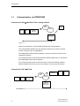
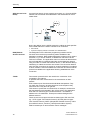
1.1
Communication via GPRS/GSM
Connection S7-200 Ù MICRO SC OPC routing software
GPRS/
GSM
OPC
Client
Internet
S7-200
PPI
SINAUT
MD720-3
SINAUT
MICRO SC
OPC Server
Figure 1-1
GPRS communication S7-200 to SINAUT MICRO SC routing software
The central SINAUT MICRO SC OPC Routing Software can connect up to 256
remote controls S7-200 via GSM/GPRS.
The GSM/GPRS modems SINAUT MD720-3 connect the S7-200 controls to the
GSM/GPRS network.
The computer with the OPC Routing Software SINAUT MICRO SC is connected to
the GSM/GPRS network via the Internet.
So an OPC client has access to the OPC Server of the OPC Routing Software
SINAUT MICRO SC and can send / receive data to / from the remote controls.
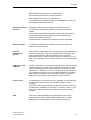
Connection S7-200 Ù S7-200
SINAUT
MD720-3
GPRS/
GSM
PPI
S7-200
Internet
S7-200
PPI
SINAUT
MD720-3
SINAUT
MICRO SC
OPC Server
Figure 1-2
8
SINAUT MICRO SC
C79000-G8900-C210
Connections
GPRS communication S7-200 to S7-200 via SINAUT MICRO SC routing software
Also the remote controls S7-200 can exchange data via the SINAUT MICRO SC
Routing Software. To do this the control sends the data to the SINAUT MICRO SC
Routing Software which forwards the data to the addressed control.
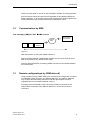
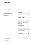
1.2
Communication by SMS
Text messages (SMS) S7-200 Ö SMS receiver
GPRS/
GSM
S7-200
PPI
SMS Empfänger
im GSM-Netz
SINAUT
MD720-3
Figure 1-3
SMS transmission by using the SINAUT MD720-3
With the SINAUT MD720-3 GSM/GPRS modems the controls S7-200 can send
SMS to any station that is able to receive SMS.
During a SMS transmission an existing GPRS connection to the SINAUT MICRO
SC is interrupted.
1.3
Remote configurations by GSM data call
Using a modem (analog, ISDN, GSM) a PC, functioning as configuration computer,
can establish a data connection to a SINAUT MD720-3. The SINAUT MD720-3
only accepts calls that identify themselves with the right telephone number
registered before in the SINAUT MD720-3 (CLIP).
According to the transmitted CLIP the incoming call will be connected to the
internal Service Interface of the SINAUT MD720-3 or to the control which is
connected.
SINAUT MICRO SC
C79000-G8900-C210
9
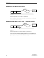
Connections
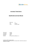
GSM data call S7-200 Õ Configuration computer
GPRS/
GSM
Fixed net
S7-200
PPI
Configuration
computer
SINAUT
MD720-3
Figure 1-4
Remote configurations of the S7-200 by CSD data call
When a call goes to the connected control this control switches to the PPI mode.
Then a software update is possible.
GSM data call SINAUT MD720-3 (Service mode) Ù Configuration computer
GPRS/
GSM
Fixed net
S7-200
PPI
Configuration
computer
SINAUT
MD720-3
Figure 1-5
Remote configurations of the SINAUT MD720-3 by CSD data call
A call to the Service Interface of the SINAUT MD720-3 must be established as
PPP-connection. Then it is possible to update the software of the device via FTP
protocol (refer to chapter 9.4 Service calls in OPC mode).
10
SINAUT MICRO SC
C79000-G8900-C210
Operating condition
2.1
2
Reachability of SINAUT MICRO SC
The computer running the OPC routing software SINAUT MICRO SC needs to be
reachable from the GPRS network permanently. Therefore this computer needs to
be connected directly to the GPRS or must permanently be reachable in the
internet by DSL for example.
Caution
The computer running the OPC routing software should be turned-off only for short
period of times.
If the OPC routing software SINAUT MICRO SC is not reachable, the GPRS/GSM
modems SINAUT MD720-3 try again and again to connect to the SINAUT MICRO
SC. This generates data volume through GPRS with costs.
Avoid any times, when the SINAUT MICRO SC is turned-off or not reachable.
2.2
Firewall
Like any other computer being connected to the internet or another public IP
network, you must protect the OPC server by a firewall against attacks coming
through the connected network.
Please ensure that the configured Server Port (Default 26862; refer to 6.1
Configuration tool) is not blocked by the firewall. Otherwise the trials of the
GPRS/GSM modems to connect via GPRS will generate data volume with costs.
SINAUT MICRO SC
C79000-G8900-C210
11
Operating condition
2.3
Defined Address of the OPC Routing Software SINAUT
MICRO SC
In order that a SINAUT MD720-3 can actively establish a GPRS connection to the
OPC Server SINAUT MICRO SC, the OPC Server SINAUT MICRO SC must have
a fixed IP address. There are three ways of obtaining a fixed IP address:
Fix IP address
The server is connected to the GPRS network via a dedicated line. In this case it
has normally been assigned a fixed IP address by the network operator. (An IP
address consists of 4 numbers, separated by full stops, which can each have up to
three digits, e.g. 184.17.20.30).
OR
The server can be accessed via the Internet and has been assigned a fixed IP
address by the Internet service provider (the address can be applied for from some
Internet service providers).
Fixed IP address via DynamicDNS provider
The server can be accessed via the Internet and is assigned dynamic IP addresses
but he is registered with a DynamicDNS provider (DNS = Domain Name Server) see Glossary. Thus, he has a fixed name (URL = Uniform Resource Locator) in
URL format.
2.4
GPRS subscriber contract
To use the SINAUT MICRO SC and the GPRS modem SINAUT MD720-3
Requirements for using the SINAUT MICRO SC and the SINAUT MD720-3:
12
•
subscriber contract with a GSM network operator (e.g. T-Mobile, Vodafone, EPlus, O2) that supports GPRS
•
release of the GPRS for the user in question by the network operator.
SINAUT MICRO SC
C79000-G8900-C210
Operating condition
2.5
Necessary information
Please have the following information available before you start to configure the
SINAUT MICRO SC and the SPS program modules:
Information about GSM / GPRS
You will get this information from your GSM/GPRS network provider, e.g. on his
Web pages, from his account manager or from his customer service.
APN (Access Point Name) : .............................................................................
Name of the gateway to the Internet, Intranet.
User name : ...............................................................................................
(Optional, depends on the network provider)
Passwort : .......................................................................................................
(Optional, depends on the network provider)
DNS1 : ............................................................................................................
(Optional, only required for Hostname addressing )
DNS2 : ............................................................................................................
(Optional, only required for Hostname addressing as backup for DNS1)
Information about the Internet / GPRS access
You will get this information from your network administrator, your internet provider
or, if you have a direct connection to the GPRS net from your GSM/GPRS provider.
Host name : ...............................................................................................
or
IP address : ...............................................................................................
of the computer running the OPC Routing Software SINAUT MICRO SC.
SINAUT MICRO SC
C79000-G8900-C210
13
Operating condition
14
SINAUT MICRO SC
C79000-G8900-C210
To establish the system
3
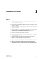
Approach
1. Get the necessary information about the your internet and GPRS access, see
Necessary information, chapter 2.5.
2. Install the OPC Routing Software SINAUT MICRO SC, see Installation SINAUT
MICRO SC, chapter 4.
3. Open the configuration tool and configure the stations, see SINAUT MICRO SC
configuration, chapter 6.
4. Define the entries for the SPS program modules WDC_INIT, see PLC Program
modules, chapter 7.1. Please observe, that the definition die need to
correspond to the entries made in the configuration tool.
5. Compile the SPS program and transfer it to the SPS.
6. Insert the SIM-Karte in the GPRS modem MD 720-3 and install it, see system
manual SINAUT MD720-3.
7. Connect the GPRS modem SINAUT MD720-3 with the SPS via the PPI
adapter, see Connect / Setup the PPI adapter, chapter 9.1.
8. Connect the modem SINAUT MD720-3 to the power supply and switch on the
SPS.
9. When the modem SINAUT MD720-3 and the OPC routing software have
established the connection, the connection status will be indicated as „yellow“.
10. When the SPS has connected to the OPC routing software, the connection
status will be indicated as „green“.
SINAUT MICRO SC
C79000-G8900-C210
15
To establish the system
16
SINAUT MICRO SC
C79000-G8900-C210
Installation SINAUT MICRO SC
4.1
4
System requirements
Hardware
•
PC compatible Server (INTEL or AMD); clock speed: > 1GHz recommended,
•
main memory: > 500Mbyte recommended; hard disk: > 1GByte free memory
space recommended,
•
CD-ROM drive to run the installation,
•
Network adapter and network access to the internet or the GPRS.
Operating system
Die OPC Routing Software SINAUT MICRO SC is suitable for the following
operating system
•
Microsoft Windows XP Professional ServicePack2
•
Microsoft Windows 2003 Server ServicePack1
•
Windows 2000 Professional/Server Service Pack4
Internet access
Internet access, being always accessible from „outside“ (for the GPRS modems),
i.e. having a fix IP address or a Host name (using DNS).
SINAUT MICRO SC
C79000-G8900-C210
17
Installation SINAUT MICRO SC
4.2
Installation
Administrator
To install the SINAUT MICRO SC software you need administrator rights for the
computer.
Number of connections
Depending on the license which you have acquired, the SINAUT MICRO SC
supports
•
8 connections to 8 stations
•
64 connections to 64 stations
•
256 connections to 256 stations
In addition there is a demo version available, which allows the connection to one
only station (for a limited period).
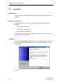
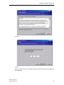
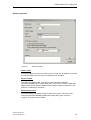
Installation
Insert the CD-ROM SINAUT MICRO SC in the CD-ROM drive of the computer and
start Setup.exe. Select the language you wish. The wizard will guide you through
the installation.
Figure 4-1
18
SINAUT MICRO SC
C79000-G8900-C210
Installation SINAUT MICRO SC
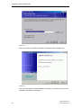
Figure 4-2
Figure 4-3
Enter the license number. The license number is written on the licence certificate of
the packaging.
SINAUT MICRO SC
C79000-G8900-C210
19
Installation SINAUT MICRO SC
Figure 4-4
Select the directory the SINAUT MICRO SC software shall be installed into.
Figure 4-5
After you have start the SINAUT MICRO SC software, you will find an icon for this
software in the task bar of Windows.
20
SINAUT MICRO SC
C79000-G8900-C210
OPC Routing Software SINAUT
MICRO SC
5
Any OPC client gains access to the actual data in the connected controls by means
of the OPC Routing Software SINAUT MICRO. With the software you can also
display the status information of each of the GPRS connections to the controls.
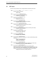
5.1
OPC Server
The SINAUT MICRO SC OPC Server has the name „M2MOPC.OPC.1“. If the OPC
client offers a list of all OPC servers you have to choose the corresponding entry.
Or write the name in the field.
Figure 5-1: A server entry in WinCC flexible (example)
SINAUT MICRO SC
C79000-G8900-C210
21
OPC Routing Software SINAUT MICRO SC
5.2
OPC Items
The OPC server provides for each configured station the following OPC items:
MSC:[<stationname>]DB1,{<type>}<address>{,<count>}
Access to the PLC’s memory
Read / Write
MSC:[<stationnname>]GPRSConnected
GPRS connection is currently established
Datatype: Bool, Read only
MSC:[<stationname>]SignalQuality
GSM signal quality (0..31)
Datatype: Byte, Read only
MSC:[<stationname>]BytesReceived
Counter for received bytes (counted by the modem)
Datatype: DWord, Read only
MSC:[<stationname>]BytesTransmitted
Counter for transmitted bytes (counted by the modem)
Datatype: DWord, Read only
MSC:[<stationname>]BytesTotal
Counter for total transmitted and sent bytes (counted by the modem)
Datatype: DWord, Read only
MSC:[<stationname>]Firmware
The GPRS modem’s firmware version
Datatype: String, Read only
MSC:[<stationname>]DeviceID
The GPRS modem’s device type ID
Datatype: String, Read only
MSC:[<stationname>]PLCConnected
Communication with the PLC program (i.e. with the GPRS library) works
error free.
FALSE: Communication fault
TRUE: Communication ok
Datatype: Bool, Read only
MSC:[<stationname>]RefreshValues
Command to update all values of the PLC variable’s by the OPC client.
Datatype: Bool, Write only, reading results to 0
MSC:[<stationname>]RefreshStatus
Command to test the connection to the PLC by the OPC client.
With this command the user is able to test the connection to the PLC
from inside the OPC client independently to the periodic functional calls.
(After this command the PLCConnected field holds the current status.)
Datatype: Bool, Write only, reading results to 0
22
SINAUT MICRO SC
C79000-G8900-C210
OPC Routing Software SINAUT MICRO SC
Notice
When a new OPC item at the SINAUT MICRO SC OPC server is created, at the
first time 64 bytes will be readout of the CPUs memory to optimize GPRS data
volume. If the memory address is at the memory edge of the CPU, error messages
may occur at the SINAUT MICRO SC. These error messages can be ignored.
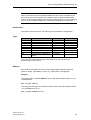
Stationname:
The station’s name to access. This name is part of the station’s configuration.
Type:
Term
B
W
D
CHAR
INT
DINT
REAL
STRING
DT
Description
Byte (unsigned)
Word (unsigned)
Doubleword (unsigned)
Byte (signed)
Word (signed)
Doubleword (signed)
Floating point number
String with fixed length
Date and time, 8 Byte BCD
format
OLE datatype
VT_UI1
VT_UI2
VT_UI4
VT_I1
VT_I2
VT_I4
VT_R4
VT_BSTR
VT_DATE
S7-200 datatype
BYTE
WORD
DWORD
BYTE
INT
DINT
REAL
STRING
The conversion of the different byte order between the PC and the PLC is
performed by the OPC server.
Address:
Byte-offset of the variable in the PLC. With strings additionally there has to be
given the length , separated by a point, e.g. <Byte-offset>.<stringlength>.
Example:
The integer value of variable VW100 in the S7-200 with the station name „S1“ e.g.
is addressed as:
MSC:[S1]DB1,INT100
The string with the length 12 at address 1500 of the S7-200 with the station name
„S1“ are addressed e.g. as:
MSC:[S1]DB1,STRING1500.12
SINAUT MICRO SC
C79000-G8900-C210
23
OPC Routing Software SINAUT MICRO SC
Count:
(optional)
Number of array elements that have to be accessed starting with the offset given in
address. If no number is determined, a single variable will be accessed.
A data block in the remote station is always mapped to DB1.
Example:
8 Bytes starting at address 500 of the S7-200 with the stationname „S1“ are
addressed e.g. as:
TSC:[S1]DB1,B500,8
Notice
The signal quality as well as the data volume counters are not updated every time
because costs for higher data volume are generated. The information are updated
in periodic time intervals (about every hour). This interval is appropriate for
monitoring the station’s running behaviour. Updating these values by synchronous
reading commands from the OPC client is possible at any time.
Refresh_Values
After the start of the OPC clients it is necessary to set the bit „Refresh Values“ to 1.
Only then the SPS will tramit the actual values.
5.3
OPC access path
In case the OPC client allows to define an access path, the stationname can be
used as access path and the address as item ID.
Example:
Access path:
MSC:[S1]
Item ID:
DB1,INT100
Alternatively the complete address can be given as OPC item ID (with an empty
access path).
24
SINAUT MICRO SC
C79000-G8900-C210
OPC Routing Software SINAUT MICRO SC
Example:
5.4
Access path:
-
Item ID:
MSC:[S1]DB1,INT100
Address Space Browsing
The OPC server supports hierarchically Address Space Browsing.
When browsing the data on the PLC there’s an asterisk „*“ given in the Item ID
instead of the address. That one has to be replaced by the requested byte-offset.
5.5
Example: Variable entries at WinCC flexible
Figure 5-2: Example variable entries at WinCC flexible
SINAUT MICRO SC
C79000-G8900-C210
25
OPC Routing Software SINAUT MICRO SC
26
SINAUT MICRO SC
C79000-G8900-C210
SINAUT MICRO SC configuration
6.1
6
Configuration tool
SINAUT MICRO SC provides process remote control via GPRS (General Packet
Radio Service). The system provides communication for the connected stations
with each other and access to all stations over an OPC server. This "SINAUT
MICRO SC" configuration tool is used to configure and monitor all stations
connected to the system. A station consists of a Siemens S7-200 PLC and a
GPRS modem SINAUT MD720-3.
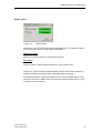
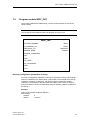
Main window
Figure 6-1
Main window
The main dialog shows a list of all configured stations. For each station the current
state is indicated:
The station is disconnected
The GPRS modem is connected to the server but the communication with
the PLC isn't possible (e.g. because the PLC isn't in RUN mode or the
wire between the PLC and the modem is broken)
The station is connected
SINAUT MICRO SC
C79000-G8900-C210
27
SINAUT MICRO SC configuration
The menu bar provides the following options:
•
File
•
Exit
Closes the configuration tool (the server keeps on running).
•
Extras
• Settings
System-wide settings
•
?
•
•
Help
Opens this help
Info
Shows license information
The buttons on the right side are for processing the connected stations.
Add
Adds a new station to the system. A dialog is opened, to edit the properties of the
new station.
Edit
Opens a dialog to edit the properties of the selected station.
Delete
Removes the selected station from the system.
Test status
Tests the current connection status of the selected station and opens a dialog to
show it.
The station status can also be tested by double clicking on a station in the list.
Status matrix
Shows the status of all configured stations in form of an open matrix.
Close
Terminates the configuration tool.
28
SINAUT MICRO SC
C79000-G8900-C210
SINAUT MICRO SC configuration
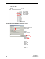
Station properties
Figure 6-2
Station properties
Station name
The specific station's name. This name must be unique over all stations. This name
must be provided in the OPC client for addressing the variables.
Station number
The station's unique number. This number must match the parameter
STATION_NUMBER when calling WDC_INIT. This number is used as destination
address with communication between PLCs. Possible values are between 1 and
65535, 0 is reserved for the server.
GPRS modem name
The name used by the GPRS modem for login at the server. This name must
match the parameter MODEM_NAME when calling WDC_INIT in the PLC
program. This name can't be edited.
SINAUT MICRO SC
C79000-G8900-C210
29
SINAUT MICRO SC configuration
GPRS modem password
The password used by the GPRS modem for login at the server. This password
must match MODEM_PASSWORD when calling WDC_INIT in the PLC program.
This password is proposed depending on the station number but can be changed
at any time.
SPS status monitoring
Indicates if and how the connection to the PLC is monitored in periodic intervals.
•
Status monitoring deactivated
The connection to the PLC is not monitored. No additional costs are created.
•
Status monitoring by value updates
The connection to the PLC is monitored by updating all values from the PLC in
the configured time interval. With this option it might not be necessary to update
analogue values and counters by the PLC program in periodic intervals.
•
Status monitoring by RealTimeClock synchronization
The connection to the PLC is monitored by synchronizing the PLC real time
clock in the configured interval.
Even if this option is not selected, the PLC real time clock is synchronized once
a day.
The Interval determines the frequency for status monitoring.
Notice
The status monitoring has the function to test and to indicate, if the configured
connection is still available. Often the status monitoring function is also necessary
to keep the connection alive. A lot of network operators disconnect connections
automatically if no data has been transmitted for a period of time. This can be
avoided, when frequently status requests are transmitted.
If you do not have already experiences with your GPRS service, you should
select an interval of 15 minutes and you should use Status monitoring by
RealTimeClock synchronization.
Try if the connections are stable also, if you use intervals greater than 15 minutes
and accordingly select smaller intervals if your connections are often interrupted.
Warning
With frequent status test calls higher costs may be caused, because of higher
data volume.
Comment
Any comment regarding this station.
30
SINAUT MICRO SC
C79000-G8900-C210
SINAUT MICRO SC configuration
Station status
Figure 6-3
Station status
Shows the current connection status of the selected station. The status is checked
by an active call to the PLC when opening this dialog.
GPRS connection
Shows if the GPRS modem is connected to the server.
PLC status
Shows if there's a communication between the server and the PLC.
There's only communication possible between the OPC server and the stations or
between the stations with each other, if both fields show connected.
If the GPRS modem is connected but the PLC isn't, then a possible reason could
be that the PLC isn't in RUN mode or the serial connection between the PLC (port
0) and the modem is broken.
SINAUT MICRO SC
C79000-G8900-C210
31
SINAUT MICRO SC configuration
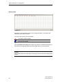
Status matrix
Figure 6-4
Shows the current connection status of all configured stations. The stations are
identified by their station number.
The color coding shows the current state:
The station is disconnected.
The GPRS modem is connected to the server but communication with
the PLC isn't possible.
The station is connected
With Test status of all stations the status of all stations is updated. Depending on
the number of configured stations this action might last for up to 30 seconds.
Caution
With frequent status test calls higher costs may be caused, because of higher data
volume.
32
SINAUT MICRO SC
C79000-G8900-C210
SINAUT MICRO SC configuration
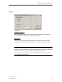
Settings
Figure 6-5
Language selection
Here the language used for the user interface can be selected. If you select an
other language it is active after a restart of the program.
Server Port
Here the TCP/IP port the GPRS modems use to connect to the server can be
configured. Possible values are between 1025 and 32767, the default is 26862.
Notice:
The port as configured here must match the setting in all PLC programs. Otherwise
there won’t be any connection between the station and the server!
After setting another server port you must restart the OPC server. Only then the
new setting becomes effective.
SINAUT MICRO SC
C79000-G8900-C210
33
SINAUT MICRO SC configuration
34
SINAUT MICRO SC
C79000-G8900-C210
PLC Library SINAUT MICRO SC
7
For wireless GPRS communication a GSM/GPRS-Modem SINAUT MD720-3 is
connected to the PLC S7-200. The GSM/GPRS modem is configured and
controlled by program modules of the S7-200.
The PLC library SINAUT MICRO SC offers the possibility to communicate with the
OPC routing software SINAUT MICRO SC“ as well as with other control systems
via GPRS.
Please observe too the PLC library PLC Library SINAUT MICRO SC Flex Px in
chapter 8.
PLC library SINAUT MICRO SC
All PLC program modules of the PLC library are used together to configure the
GSM/GPRS-Modem SINAUT MD720-3 and to communicate with the SINAUT
MICRO SC.
The PLC program modules are executable on the S7-200 CPUs 224, 224XP and
226.
The PLC library uses port 0 of the PLC.
PLC library SINAUT MICRO SC Flex Px
This PLC library includes a PLC program module for the configuration of the
GSM/GPRS-Modem SINAUT MD720-3 and several PLC program modules to
communicate with the SINAUT MICRO SC.
The PLC program modules for configuration and for control and communication are
used separately. That allows the PCL program to become smaller and therefore it
is executable on the S7-200 CPUs 221, 222, 224, 224XP and 226.
SINAUT MICRO SC
C79000-G8900-C210
35
PLC Library SINAUT MICRO SC
7.1
PLC Program modules
The PLC library provides the following modules for developing a GPRS
communication.
•
WDC_INIT
Parameter setting of modem
•
WDC_SEND
Execution of transmission tasks
•
WDC_RECEIVE
Processing of received data
•
WDC_CONTROL
Controlling of communication mode (PPI resp. Freeport)
The library always uses port 0 of the PLC.
36
SINAUT MICRO SC
C79000-G8900-C210
PLC Library SINAUT MICRO SC
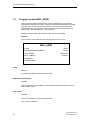
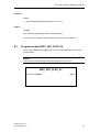
7.2
Program module WDC_INIT
The module initialises the GRPS library, the PLC serial interface as well as the
GPRS modem.
Remark:
This module is to be called from the user program once per cycle.
WDC_INIT
STATION_NUMBER
BUSY
IP_ADDRESS_CS
DONE
DESTPORT_CS
ABORTED
MODEM_NAME
ERROR
MODEM_PASSWORD
PIN
APN
AP_USER
AP_PASSWORD
DNS
CLIP
Entering configuration parameters as string
A lot of the configuration parameters need to be entered as strings. These strings
need to be defined in the „data module“ of MicroWIN. The first Byte of the strings
contains the number of characters, the following Bytes contains the several
characters. The disposal of the parameter to the WDC_INIT module is made by
giving the reference to the corresponding string (&-operator) („Memory address of
the strings“).
Example:
Name of the modem at address VB1830.
Data module:
VB1830
6
VB1831
'modem1'
SINAUT MICRO SC
C79000-G8900-C210
37
PLC Library SINAUT MICRO SC
Call of WDC_INIT:
Corresponding entries MICRO SC Ù SPS program modules
//
//Data module comments
//
//Press F1 to start Help and a
program example.
//
VB1800 11
VB1801 '68.225.63.9'
VB1820 5
VB1821 '26862'
VB1830 6
VB1831 'modem1'
VB1840 7
VB1841 'secret1'
VB1850 4
VB1851 '0000'
VB1860 16
VB1861 'internet.t-d1.de'
VB1910 5
VB1911 'guest'
VB1920 5
VB1921 'guest'
VB1930 26
VB1931 '194.25.2.131;193.254.160.1'
VB1960 6
VB1961 '*;;;;;'
38
SINAUT MICRO SC
C79000-G8900-C210
PLC Library SINAUT MICRO SC
STATION_NUMBER
(WORD)
Logical address of local station.
IP_ADDRESS_CS
(DWORD (Saving address of string))
IP-address or DNS of server (Central Station).
DESTPORT_CS
(DWORD (Speicheradresse des Strings))
TCP/IP Port des Servers.
MODEM_NAME
(DWORD (Saving address of string))
Name for GPRS modem registration to the server.
MODEM_PASSWORD
(DWORD (Saving address of string))
Password for GPRS modem registration to the server.
PIN
(DWORD (Saving address of string))
PIN for activation of SIM card.
APN
(DWORD (Saving address of string))
GPRS access point at provider (Access Point Name).
AP_USER
(DWORD (Saving address of string))
Name for registration to GPRS access point.
SINAUT MICRO SC
C79000-G8900-C210
39
PLC Library SINAUT MICRO SC
AP_PASSWORD
(DWORD (Saving address of string))
Password for registration at GPRS access point.
DNS
(DWORD (Saving address of string))
IP addresses of DomainNameServer of GSM provider.
If two DNS servers are to be specified, these can be divided by semicolon (;)
(DNS1;DNS2), e.g. „194.25.2.131;193.254.160.1“.
CLIP
(DWORD (Saving address of string))
List of all valid dial-in numbers at the station. Several listing entries are divided by
semicolon (;). The sequence is specified, in each case three numbers for the dial-in
to the application (COM) and for the dial-in to the modem service-operation
(SERVICE).
<COM_CLIP_0>;<COM_CLIP_1>;<COM_CLIP_2>;<SERVICE_CLIP_0>;<SERVI
CE_CLIP_1>;<SERVICE_CLIP_2>
Only calls are accepted of valid phone numbers.
The entered numbers for SERVICE_CLIP and COM_CLIP must be different. If
same numbers has been entered the SERVICE_CLIP priority.
Wildcard characters (*) can be used for the definition of phone number groups.
Example:
+49123123* all numbers are accepted starting with +49123123.
Caution
Enter as CLIP a phone number, which you can use to call the PLC or the SINAUT
MD720-3, to download a new software.
If you do not enter a CLIP, you cannot use this teleservice function.
BUSY
(BOOL)
0 Inactive
1 The initialization sequence is in process at the moment.
40
SINAUT MICRO SC
C79000-G8900-C210
PLC Library SINAUT MICRO SC
DONE
(BOOL)
1 The initialization has been successfully accomplished.
ABORTED
(BOOL)
1 The initialization has been aborted due to an error.
ERROR
(WORD)
Error number, describing the result of the processing.
A list of all error numbers and their meaning is to be found in chapter 7.6.
SINAUT MICRO SC
C79000-G8900-C210
41
PLC Library SINAUT MICRO SC
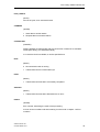
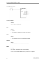
7.3
Program module WDC_SEND
This module processes all transmission tasks, initiated by the user program
(transmission impulse via START). Thereby a new transmission task is accepted
only then when no other task is active (BUSY must be 0). In the context of a
transmission task, it is possible to send a user data block with specification of
starting index and the length to the remote station.
While BUSY is set parameters of the module must not bee edited.
Remark:
This module is to be called from the user program once per cycle.
WDC_SEND
START
BUSY
REMOTESTATIONADDRESS
DONE
DATA_START
DATA_LENGTH
ABORTED
ERROR
COMMAND
CURRENTTIME
START
(BOOL)
A positive edge starts a new transmission task.
REMOTESTATIONADDRESS
(WORD)
Logical address of remote station, to which data should be sent and/or of which
data should be read.
DATA_START
(WORD)
Index of first data byte, to be sent and/or read.
E.g.: „1500“ for VB1500
42
SINAUT MICRO SC
C79000-G8900-C210
PLC Library SINAUT MICRO SC
DATA_LENGTH
(BYTE)
Amount of bytes, to be sent and/or read.
COMMAND
(WORD)
1 Send data to another station
2 Request data from another station
CURRENTTIME
(DWORD)
Starting address of 8-Byte buffer with the current time in Siemens S7-200 BCD
format (see READ_RTC standard module).
If no real-time clock is available, 0 can be specified here.
BUSY
(BOOL)
0 No transmission task is running
1 Transmission task is not terminated yet
DONE
(BOOL)
1 Transmission task has been successfully completed.
ABORTED
(BOOL)
1 Transmission task has been aborted due to an error.
ERROR
(WORD)
Error number, describing the result of the processing.
A list of all error numbers and their meaning is to be found in chapter 7.6 Error
numbers.
SINAUT MICRO SC
C79000-G8900-C210
43
PLC Library SINAUT MICRO SC
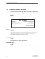
7.4
Program module WDC_RECEIVE
This module monitors the receipt buffer. When a new telegram has arrived it will be
evaluated. Received data will directly be copied to the mentioned address. To the
application the receipt of data will be signaled via the outputs DATA_START and
DATA_LENGTH.
Remark:
This module is to be called from the user program once per cycle.
WDC_RECEIVE
NEWTIME
REMOTESTATIONADDRESS
RECVBUFFER_START
DATA_START
RECVBUFFER_LENGTH
DATA_LENGTH
NEWTIME_RECEIVED
NEWTIME
(DWORD)
Starting address of 8-Bytes buffer, to which the received system time should be
copied (Siemens S7-200 BCD format (see READ_RTC standard module).
If 0 is specified, received time stamps will be rejected.
RECVBUFFER_START
(WORD)
Start index of the part of memory that is released.
RECVBUFFER_LENGTH
(WORD)
Length of the space for data that is released to store the received data in it (in
Bytes).
44
SINAUT MICRO SC
C79000-G8900-C210
PLC Library SINAUT MICRO SC
REMOTESTATIONADDRESS
(WORD)
Logical address of remote station (PLC or OPC server), that has transmitted the
message.
DATA_START
(WORD)
Starting index of received data.
DATA_LENGTH
(BYTE)
If data has been received, amount of received bytes.
If no data has been received, 0.
NEWTIME_RECEIVED
(BOOL)
Flag, which signals the receipt of a new system time. This bit and the value of
NEWTIME should be used as parameter of SET_RTC in the user program, to
synchronise the real-time clock.
This bit can be ignored if no real-time clock is available.
SINAUT MICRO SC
C79000-G8900-C210
45
PLC Library SINAUT MICRO SC
7.5
Program module WDC_CONTROL
This WDC module indicates the current operation mode of the GPRS modem and
the library.
This module enables the modem switching in the AT command mode, to become
access directly to the modem via AT commands from the user program (call via
positive flank ACT_AT_MODE).
This module enables the change to the „normal operation“ after a remote
programming session via CSD call to the GPRS modem (call via rising edge at
ACT_GPRS_SERVICE).
With separation of the CSD connection, the GPRS modem changes automatically
back into the GPRS mode. The controler is not able to recognise the end of the
phone connection. To return in any way to the GPRS communication, a time
delayed switch has to be activated in the freeport mode before connection end via
module WDC_CONTROL from the variable table of MicroWin. Therefore in
DELAY_TIME_GRPS the delay time must be specified and the switch to
ACT_GPRS_SERVICE must be activated.
For security a maximum time interval for the „not GPRS operation“ (this means
INT_MODE <> 1) can be specified (MAX_TIME_AT). After this time the modem is
switched back in any case to the GPRS operation mode, if the PLC is set to RUN.
Remark
This module is to be called from the user program once per cycle.
WDC_CONTROL
ACT_GPRS_SERVICE
INT_MODE
ACT_AT_MODE
BUSY
DELAY_TIME_GPRS
DONE
MAX_TIME_AT
ABORTED
ERROR
46
SINAUT MICRO SC
C79000-G8900-C210
PLC Library SINAUT MICRO SC
ACT_GPRS_SERVICE
(BOOL)
With consideration of the delay time DELAY_TIME_GPRS a rising edge activates
the freeport mode of the interface 0 and puts the modem into the GRPS mode.
ACT_AT_MODE
(BOOL)
A rising edge activates the AT command mode to the modem.
DELAY_TIME_GPRS
(WORD)
Delay time in seconds between rising edge of ACT_GPRS_SERVICE and the
switching in the freeport mode.
MAX_TIME_AT
(WORD)
Standard time in seconds, after which the modem should be switched back in any
case to GPRS mode (e.g. 1800 seconds, i.e. 30 minutes).
INT_MODE
(WORD)
0 Operation mode changing:
Interface is being switched / not yet initialised (Start status after activation)
1 Normal operation:
Interface is in freeport mode, modem is in GPRS mode.
2 Initialisation:
Interface is in freeport mode, modem is in configuration mode (see WDC_INIT,
chapter 1.2.1)
3 AT-Mode:
Interface is in freeport mode, modem is in AT command mode.
With the aid of appropriate AT commands, it is possible f.i. to call up transaction
services from SMS messages.
4 Remote programming:
Interface is in PPI mode, modem is in CSD operation mode BUSY
SINAUT MICRO SC
C79000-G8900-C210
47
PLC Library SINAUT MICRO SC
BUSY
(BOOL)
DONE
(BOOL)
1 A mode change is carried out
ABORTED
(BOOL)
1 Mode change has been successfully completed.
ERROR
(WORD)
Error list with cause of missed mode change.
A list of all error numbers and their meaning is to be found in chapter 7.6 Error
numbers.
48
SINAUT MICRO SC
C79000-G8900-C210
PLC Library SINAUT MICRO SC
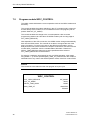
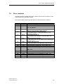
7.6
Error numbers
The WDC program modules return error numbers if errors have occurred, in order
to describe the error situation in detail.
The following table contains all supported error numbers and their meaning.
Error number
dec
hex
0
0000
1
0001
2
0002
10
000A
11
000B
12
000C
13
000D
257
258
259
260
0101
0102
0103
0104
261
262
263
264
265
266
0105
0106
0107
0108
0109
010A
SINAUT MICRO SC
C79000-G8900-C210
Meaning
No error
General error
Error, not specified
Timeout
During function process a timeout occurred
Unknown Communication Participator
The specified station in „DestinationAddress“ is not
known to the system
Invalid Starting Address
The specified starting address of the user data is not
valid
Invalid Length Specification
The specified number of user data is not acceptable (this
means too long)
Function not supported
The requested task is not supported („FunctionCode“)
Invalid parameter „IP_ADDRESS_CS“ in „WDC_INIT“
Invalid parameter „DESTPORT_CS“ in „WDC_INIT“
Invalid parameter „MODEM_USER“ in „WDC_INIT“
Invalid parameter „MODEM_PASSWORD“ in
„WDC_INIT“
Invalid parameter „PIN“ in „WDC_INIT“
Invalid parameter „APN“ in „WDC_INIT“
Invalid parameter „AP_USER“ in „WDC_INIT“
Invalid parameter „AP_PASSWORD“ in „WDC_INIT“
Invalid parameter „DNS“ in „WDC_INIT“
Invalid parameter „CLIP“ in „WDC_INIT“
49
PLC Library SINAUT MICRO SC
50
SINAUT MICRO SC
C79000-G8900-C210
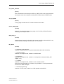
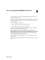
PLC Library SINAUT MICRO SC Flex Px
8
For wireless GPRS communication a GSM/GPRS-Modem SINAUT MD720-3 is
connected to the PLC S7-200.
The PLC library SINAUT MICRO SC Flex Px offers the possibility to communicate
with the OPC routing software SINAUT MICRO SC as well as with other control
systems via GPRS.
The PLC library differs in two variants:
•
SINAUT MICRO SC Flex P0 communication via port 0
•
SINAUT MICRO SC Flex P1 communication via port 1
At first use the PLC program module WDC_CONFIG_FLEX_Px to configure nonvolatile the GSM/GPRS-Modem SINAUT MD720-3.
After the configuration was successful, replace the PLC program module
WDC_CONFIG_FLEX_Px with the other PLC program modules of the PLC library
SINAUT MICRO SC Flex Px. These PLC program modules take the control of the
GSM/GPRS-Modem SINAUT MD720-3 and the communication with the OPCServer SINAUT MICRO SC in operational mode.
The PLC program modules are executable on the S7-200 CPUs 221, 222, 224,
224XP and 226.
The PLC library SINAUT MICRO SC Flex Px supports the PLC port 0 (x = 0) and
port 1 (x = 1).
SINAUT MICRO SC
C79000-G8900-C210
51
PLC Library SINAUT MICRO SC Flex Px
8.1
PLC Program modules
The PLC library provides the following modules for developing a GPRS
communication.
•
WDC_CONFIG_FLEX_Px
Parameter setting of modem SINAUT MD720-3
•
WDC_INIT_FLEX_Px
Parameter setting of communication interface
•
WDC_SEND_FLEX_Px
Execution of transmission tasks
•
WDC_RECEIVE_FLEX_Px
Processing of received data
Program modules being marked with FLEX_P0 always uses port 0 of the PLC.
Program modules being marked with FLEX_P1 always uses port 1 of the PLC.
52
SINAUT MICRO SC
C79000-G8900-C210
PLC Library SINAUT MICRO SC Flex Px
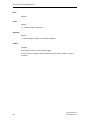
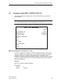
8.2
Program module WDC_CONFIG_FLEX_Px
The module initialises the GRPS library, the PLC serial interface as well as the
GPRS modem.
Remark:
This module is to be called from the user program once per cycle.
WDC_INIT_advanced
BUSY
IP_ADDRESS_CS
DONE
DESTPORT_CS
ABORTED
MODEM_NAME
ERROR
MODEM_PASSWORD
PIN
APN
AP_USER
AP_PASSWORD
DNS
CLIP
Entering configuration parameters as string
A lot of the configuration parameters need to be entered as strings. These strings
need to be defined in the „data module“ of MicroWIN. The first Byte of the strings
contains the number of characters, the following Bytes contains the several
characters. The disposal of the parameter to the WDC_CONFIG_FLEX_Px module
is made by giving the reference to the corresponding string (&-operator) („Memory
address of the strings“).
Example:
Name of the modem at address VB1830.
Data module:
VB1830
VB1831
SINAUT MICRO SC
C79000-G8900-C210
6
'modem1'
53
PLC Library SINAUT MICRO SC Flex Px
Call of WDC_INIT_advanced:
Corresponding entries MICRO SC Ù SPS program modules
//
//Data module comments
//
//Press F1 to start Help and a
program example.
//
VB1800 11
VB1801 '68.225.63.9'
VB1820 5
VB1821 '26862'
VB1830 6
VB1831 'modem1'
VB1840 7
VB1841 'secret1'
VB1850 4
VB1851 '0000'
VB1860 16
VB1861 'internet.t-d1.de'
VB1910 5
VB1911 'guest'
VB1920 5
VB1921 'guest'
VB1930 26
VB1931 '194.25.2.131;193.254.160.1'
VB1960 6
VB1961 '*;;;;;'
54
SINAUT MICRO SC
C79000-G8900-C210
PLC Library SINAUT MICRO SC Flex Px
IP_ADDRESS_CS
(DWORD (Saving address of string))
IP-address or DNS of server (Central Station).
DESTPORT_CS
(DWORD (Speicheradresse des Strings))
TCP/IP Port des Servers.
MODEM_NAME
(DWORD (Saving address of string))
Name for GPRS modem registration to the server.
MODEM_PASSWORD
(DWORD (Saving address of string))
Password for GPRS modem registration to the server.
PIN
(DWORD (Saving address of string))
PIN for activation of SIM card.
APN
(DWORD (Saving address of string))
GPRS access point at provider (Access Point Name).
AP_USER
(DWORD (Saving address of string))
Name for registration to GPRS access point.
AP_PASSWORD
(DWORD (Saving address of string))
Password for registration at GPRS access point.
SINAUT MICRO SC
C79000-G8900-C210
55
PLC Library SINAUT MICRO SC Flex Px
DNS
(DWORD (Saving address of string))
IP addresses of DomainNameServer of GSM provider.
If two DNS servers are to be specified, these can be divided by semicolon (;)
(DNS1;DNS2), e.g. „194.25.2.131;193.254.160.1“.
CLIP
(DWORD (Saving address of string))
List of all valid dial-in numbers at the station. Several listing entries are divided by
semicolon (;). The sequence is specified, in each case three numbers for the dial-in
to the application (COM) and for the dial-in to the modem service-operation
(SERVICE).
<COM_CLIP_0>;<COM_CLIP_1>;<COM_CLIP_2>;<SERVICE_CLIP_0>;<SERVI
CE_CLIP_1>;<SERVICE_CLIP_2>
Only calls are accepted of valid phone numbers.
The entered numbers for SERVICE_CLIP and COM_CLIP must be different. If
same numbers has been entered the SERVICE_CLIP priority.
Wildcard characters (*) can be used for the definition of phone number groups.
Example:
+49123123* all numbers are accepted starting with +49123123.
Caution
Enter as CLIP a phone number, which you can use to call the PLC or the SINAUT
MD720-3, to download a new software.
If you do not enter a CLIP, you cannot use this teleservice function.
BUSY
(BOOL)
0 Inactive
1 The initialization sequence is in process at the moment.
DONE
(BOOL)
1 The initialization has been successfully accomplished.
56
SINAUT MICRO SC
C79000-G8900-C210
PLC Library SINAUT MICRO SC Flex Px
ABORTED
(BOOL)
1 The initialization has been aborted due to an error.
ERROR
(WORD)
Error number, describing the result of the processing.
A list of all error numbers and their meaning is to be found in chapter 7.6.
8.3
Program module WDC_INIT_FLEX_Px
The module initialises the GPRS library, the PLC serial interface as well as the
GPRS modem.
Remark:
This module is to be called from the user program once per cycle.
WDC_INIT_FLEX_Px
STATION_NUMBER
SINAUT MICRO SC
C79000-G8900-C210
BUSY
57
PLC Library SINAUT MICRO SC Flex Px
Call of WDC_INIT_smart:
STATION_NUMBER
(WORD)
Logical address of local station.
BUSY
(BOOL)
0 Inactive
1 The initialization sequence is in process at the moment.
DONE
(BOOL)
1 The initialization has been successfully accomplished.
ABORTED
(BOOL)
1 The initialization has been aborted due to an error.
ERROR
(WORD)
Error number, describing the result of the processing.
A list of all error numbers and their meaning is to be found in chapter 0
58
SINAUT MICRO SC
C79000-G8900-C210
PLC Library SINAUT MICRO SC Flex Px
8.4
Program module WDC_SEND_FLEX_Px
This module processes all transmission tasks, initiated by the user program
(transmission impulse via START). Thereby a new transmission task is accepted
only then when no other task is active (BUSY must be 0). In the context of a
transmission task, it is possible to send a user data block with specification of
starting index and the length to the remote station.
While BUSY is set parameters of the module must not bee edited.
Remark
This module is to be called from the user program once per cycle.
WDC_SEND_FLEX_Px
START
BUSY
REMOTESTATIONADDRESS
DONE
DATA_START
DATA_LENGTH
ABORTED
ERROR
COMMAND
CURRENTTIME
START
(BOOL)
A positive edge starts a new transmission task.
REMOTESTATIONADDRESS
(WORD)
Logical address of remote station, to which data should be sent and/or of which
data should be read.
DATA_START
(WORD)
Index of first data byte, to be sent and/or read.
E.g.: „1500“ for VB1500
SINAUT MICRO SC
C79000-G8900-C210
59
PLC Library SINAUT MICRO SC Flex Px
DATA_LENGTH
(BYTE)
Amount of bytes, to be sent and/or read.
COMMAND
(WORD)
1 Send data to another station
2 Request data from another station
CURRENTTIME
(DWORD)
Starting address of 8-Byte buffer with the current time in Siemens S7-200 BCD
format (see READ_RTC standard module).
If no real-time clock is available, 0 can be specified here.
BUSY
(BOOL)
0 No transmission task is running
1 Transmission task is not terminated yet
DONE
(BOOL)
1 Transmission task has been successfully completed.
ABORTED
(BOOL)
1 Transmission task has been aborted due to an error.
ERROR
(WORD)
Error number, describing the result of the processing.
A list of all error numbers and their meaning is to be found in chapter 7.6 Error
numbers.
60
SINAUT MICRO SC
C79000-G8900-C210
PLC Library SINAUT MICRO SC Flex Px
8.5
Program module WDC_RECEIVE_FLEX_Px
This module monitors the receipt buffer. When a new telegram has arrived it will be
evaluated. Received data will directly be copied to the mentioned address. To the
application the receipt of data will be signaled via the outputs DATA_START and
DATA_LENGTH.
Remark
This module is to be called from the user program once per cycle.
WDC_RECEIVE_FLEX_Px
NEWTIME
REMOTESTATIONADDRESS
RECVBUFFER_START
DATA_START
RECVBUFFER_LENGTH
DATA_LENGTH
NEWTIME_RECEIVED
NEWTIME
(DWORD)
Starting address of 8-Bytes buffer, to which the received system time should be
copied (Siemens S7-200 BCD format (see READ_RTC standard module).
If 0 is specified, received time stamps will be rejected.
RECVBUFFER_START
(WORD)
Start index of the part of memory that is released.
RECVBUFFER_LENGTH
(WORD)
Length of the space for data that is released to store the received data in it (in
Bytes).
SINAUT MICRO SC
C79000-G8900-C210
61
PLC Library SINAUT MICRO SC Flex Px
REMOTESTATIONADDRESS
(WORD)
Logical address of remote station (PLC or OPC server), that has transmitted the
message.
DATA_START
(WORD)
Starting index of received data.
DATA_LENGTH
(BYTE)
If data has been received, amount of received bytes.
If no data has been received, 0.
NEWTIME_RECEIVED
(BOOL)
Flag, which signals the receipt of a new system time. This bit and the value of
NEWTIME should be used as parameter of SET_RTC in the user program, to
synchronize the real-time clock.
This bit can be ignored if no real-time clock is available.
62
SINAUT MICRO SC
C79000-G8900-C210
MD720-3 in OPC Mode
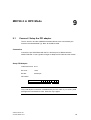
9.1
9
Connect / Setup the PPI adapter
The S7-200 PLC and the GSM/GPRS modem MD720-3 are connected by the
Siemens PPI Modemkabel Typ- Best. Nr. 6NH9701-0AD.
Connection
Connect the port PPI-RS485 with the PLC and the port PC-RS232 with the
SINAUT MD720-3. Use a gender changer to adapt the PPI cable and the modem.
Setup PPI-Adapter
Character format: 8 N 1
Bit count
:
Bit rate:
10 bit
57600 bps
DIP switch:
DIP switch no.:
Position:
1 2 3 4 5 6 7 8
1 1 1 0 0 1 1 0
Caution
Only a half duplex connection is established by the PPI-cable. If (<5-10 Sec.)-data
packages are transmited too often, data loss may happen.
SINAUT MICRO SC
C79000-G8900-C210
63
MD720-3 in OPC Mode
9.2
Prepare the SINAUT MD720-3 for the OPC mode
The GSM/GPRS-Modem SINAUT MD720-3 will be configured by the PLC S7-200
and the program modules. An additional configuration is not necessary.
9.3
SMS transmission in OPC mode
Information about the SMS transmission in OPC mode you can find in the Internet
in the SET21 examples, Beitrags-ID 22537809
9.4
Service calls in OPC mode
To download a new firmware setup a service connection to the GSM/GPRS
modem MD720-3.
You need a computer with a modem (Analogue, ISDN or GSM) and a
corresponding network access. You have installed a modem driver for the used
modem on your PC.
As SERVICE_CLIP (see chapter 7.2 Program module WDC_INIT) need to be
entered the telephone number, which you use to call the SINAUT MD720-3.
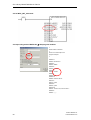
To set up a network connection
A network connection is used to communicate with the SINAUT MD720-3 in
Service mode.
1. Click Start, Control Panel.
2. In the Category View select Network and Internet Connections.
3. Select Set up a connection with the network at the office and follow the wizard
for new connections that will start.
4. Select Remote Data Transmission and click Next.
5. Select the Modem you have installed before and click Next.
6. Give a name to the new connection, e.g. Service-MD720. Then click Next.
7. Enter the telephone number the SINAUT MD720-3 uses for data calls and then
click Next.
8. Click Finish to terminate the wizard.
64
SINAUT MICRO SC
C79000-G8900-C210
MD720-3 in OPC Mode
9. In the Start-menu select Connect to and choose the connection you just have
set up, e.g. Service-MD720.
10. Click two times OK to finish the Modem Configuration and the Properties
windows
To establish a service connection
As soon as the network connection is set up you can establish the service
connection.
1. Click Start.
2. In the Start-menu select Connect to and choose the connection to the SINAUT
MD720-3.
3. Type in the user name (Default: service) and the password (Default: service)
and the click Dial.
4. When the connection is established in the Windows task bar a connection icon
is displayed.
5. Click Start, All Programs, Accessories, Command Prompt.
6. Enter: C:\WINDOWS>ftp 192.168.0.8
Then press Enter.
7. You are asked for the user name (Default: service) and for the password
(Default: service). Enter both in the right case sensitive spelling.
8. As soon as the connection is established successfully you get the message
„230 User logged in“. The prompt changes to „Ftp>“.
To update the firmware of the SINAUT MD720-3
As soon as the service connection is established you can start to upload the
firmware.
1. With Notepad (belongs to Windows) create a file with the name !cmdfile. The
file name must not have any extension (e.g.: .txt). The first line in this file is:
STORE FirmwareName.BIN
Instead of „FirmewareName.BIN“ write the name of the new firmware file.
2. At the Ftp>-prompt enter: put FirmwareName.BIN
Press Enter. Instead of „FirmewareName.BIN“ write the name of the new
firmware file.
SINAUT MICRO SC
C79000-G8900-C210
65
MD720-3 in OPC Mode
3. Then at the Ftp>-prompt enter: put !cmdfile
Press Enter.
After the firmware file and the !cmdfile file are successfully uploaded the
SINAUT MD720-3 will start to install the new firmware. This process can last
up to 10 minutes. After this the SINAUT MD720-3 restarts. Then the SINAUT
MD720-3 is ready again.
To tear-down the service connection
Tear-down the local service connection when you do not use it any more.
1. At the Ftp>-prompt enter: quit
Then press Enter.
2. Then also tear-down the network connection to the device. To do so right-click
the icon in the Windows task bar.
66
SINAUT MICRO SC
C79000-G8900-C210
Troubleshooting
10
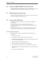
SINAUT MD720-3 and SINAUT MICRO SC do not connect
The status indication
of the SINAUT MICRO SC shows that the connection to
the SINAUT MD720-3 is not established and the LED “C” (Connect) of the SINAUT
MD720-3 is off or blinks slowly.
The SINAUT MD720-3 is not ready for Operation
Please check the LED indication of the SINAUT MD720 (refer to System manual
SINAUT MD720-3, chapter Functions of LEDs in OPC-Mode), if the SIM card is
inserted correctly and the if the PIN is accepted. If a problem is indicated, please
follow the related instructions about the PIN of the SINAUT MD720-3 System
manual.
The Signal quality at the SINAUT MD720-3 is not sufficient
Please check with the LEDs of the SINAUT MD720-3 (refer to System manual
SINAUT MD720-3, chapter Functions of LEDs in OPC-Mode), if the signal quality is
sufficient or better. Change the antennas position, until you have a sufficient or
good signal quality.
The SINAUT MD720-3 does not attach the GPRS
Please check with the LEDs of the SINAUT MD720-3 (refer to System manual
SINAUT MD720-3, chapter Functions of LEDs in OPC-Mode), if the device is
attached to the GPRS. If not, please double-check the entries for APN. AP_USER
and AP_PASSWORD in your PLC program module WDC_INIT. Pushing the SET
button of the SINAUT MD720-3, the device will send a list of the current
configuration to a connected PC running a terminal software (refer to System
manual SINAUT MD720-3, chapter Getting the current values and settings). If the
displayed APN value does not correspond to the value of your PLC program,
please double-check the connection between PLC and SINAUT MD720-3.
Please check also, if your PLC is in RUN mode.
SINAUT MICRO SC
C79000-G8900-C210
67
Troubleshooting
Using a common mobile phone with GPRS function, please check if a GPRS
Service is available in the location of your SINAUT MD720-3.
The SINAUT MD720-3 does not reach the SINAUT MICRO SC
The SINAUT MD720-3 is attached to the GPRS, but the LED “C” is off or blinks
slowly.
If the SINAUT MD720-3 is ready for operation and the signal quality is sufficient
and the device is attached to the GPRS, please check the values for
IP_ADDRESSCS, DESTPORT_CS. DNS, MODEM_NAME und
MODEM_PASSWORD which are referred to in the PLC program module
WDC_INIT. The following values are displayed at a connected PC, when you push
the SET button (refer to System manual SINAUT MD720-3, chapter Getting the
current values and settings):
Remote-Host
corresponds to
IPADDRESS_CS
Destination-Port
corresponds to
DESTPORT_CS
Server-Username corresponds to
MODEM_NAME
If the displayed values correspond to the entries of the PLC, the PLC transmits its
values to the SINAUT MD720-3 correctly. Otherwise please check the connection
between the PLC and the SINAUT MD720-3. Please compare also all values with
the corresponding parameters of the SINAUT MICRO SC.
Please check, if the SINAUT MICRO SC is reachable.
SINAUT MICRO SC is not reachable
When you have double-checked and eventually corrected all connection
Parameters of the PLC and the SINAUT MD720-3 and the connection is still not
established, eventually the SINAUT MICRO SC is not reachable.
If the SINAUT MICRO SC has already established connections to other SINAUT
MD720-3, the SINAUT MICRO SC is reachable.
If the SINAUT MICRO SC has no connection to any SINAUT MD720-3, please
check:
68
•
that the Computer running the SINAUT MICRO SC is connected to the
Internet,
•
that the server port being entered into the SINAUT MICRO SC is the same like
the value for DESTPORT_CS in the PLC program module,
•
that this server port is not blocked in any hardware or software firewall,
SINAUT MICRO SC
C79000-G8900-C210
Troubleshooting
•
that the internet address of your server (IP address or hostname) is correctly
entered in your PLC program module (IP_ADDRESS_CS Parameter),
•
that the DynDNS server is frequently updated, if you are using a DynDNS
Service to get a fixed address for your SINAUT MICRO SC.
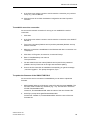
SINAUT MICRO SC and SPS do not connect
The Status indication of the SINAUT MICRO SC shows, that the connection
between SINAUT MICRO SC and SINAUT MD720-3 is established, but that the
PLC is not reachable.
Please check, if the value for Station number corresponds to the values being
entered into the PLC program module.
Please check, if the PPI cable is configured as shown in the System manual.
Data loss between SINAUT MICRO SC and PLC
A loss of data between SINAUT MICRO SC and PLC may occur, because the used
PPI cable is only capable of half-duplex connections.
Please make sure that you wait at least 5 to 10 seconds between two requests
from SINAUT MICRO SC to the PLC.
The LED “S” blinks fast (4 times per second)
If the SIM card is inserted correctly and the SIM card is not PUK-blocked, the LED
“S” blinks fast and indicates a SIM Problem. Please check and eventually reset the
SIMSTATE, refer to System manual SINAUT MD720-3, chapter PIN in OPC-Mode.
SINAUT MICRO SC
C79000-G8900-C210
69
Troubleshooting
70
SINAUT MICRO SC
C79000-G8900-C210
Glossary
DynamicDNS
providers
offer the capability of
being accessible via a
fixed Internet address
Each computer which is connected to the Internet has an IP address
(IP = Internet Protocol). An IP address consists of 4 numbers,
separated by full stops, which each have up to three digits. If the
computer is online via the telephone line per modem, per ISDN or per
ADSL it is assigned a dynamic IP address by the Internet service
provider, i.e. the address changes from session to session. Even if
the computer is online for 24 hours without interruptions (e.g. with a
flat rate) the IP address is changed from time to time.
If a local computer is to be accessible via the Internet it must have an
address which is known to the remote communication partner. Only in
this way can the communication partner establish a connection to the
local computer. However, if the address of the local computer
continually changes this is not possible, except where the operator of
the local computer has an account with a DynamicDNS provider (DNS
= Domain Name Server).
He can then define a name in URL format (URL = Uniform Resource
Locator) with this provider under which the computer shall be
accessible in the future, e.g. www.xyz.abc.de. In addition the
DynamicDNS provider provides a small program which has to be
installed and executed in the computer in question. In each Internet
session of the local computer this tool informs the DynamicDNS
provider of the computer's current IP address. Its domain name server
registers the current assignment of URL IP address and advises
this to other domain name servers in the Internet.
If a remote computer now wishes to establish a connection to the
local computer which is registered with the DynamicDNS provider the
following takes place: The remote computer uses the URL (= host
name) of the local computer as the address. This results in a
connection being established to the responsible DNS (Domain Name
Server) to determine the IP address currently assigned to this URL.
The IP address is transferred back to the remote computer which now
uses it as the destination address. This now leads to exactly the
desired local computer.
This procedure is the basis for all Internet addresses in URL format:
First a connection is established to the DNS to determine the IP
address assigned to this URL. Once that has happened this "lookedup" IP address is used to establish the connection to the desired
communication partner, i.e. to any Internet site.
You can find DynamicDNS providers on the Internet under the
following address: http://netzadmin.org/ddns-provider.php
SINAUT MICRO SC
C79000-G8900-C210
71
Glossary
APN (Access Point
Name)
(Access Point Name). Cross-network connections, e.g. from the GPRS
network into the Internet are established in the GPRS network via socalled APNs
During the dialling into the GPRS network the calling terminal specifies
via the APN with which network it wishes to be connected:
•
the Internet,
•
a private company network connected via a dedicated line.
RAS (Remote
Access Services
The designation for the Windows programming interface and its
functions which the dial-up networking makes available to the
application programs. RAS enables application programs which expect
a network, e.g. a TCP/IP network, to establish a connection via the
TAPI and a modem. The application does not notice at all that the data
are not forwarded via a network board but via the telephone network
using a modem or another transmission device. In the Windows dial-up
networking so-called connections are created. The connection data for
each of these connections is stored, for example a definition is made as
to which modem is used to establish the connection and which network
protocol is available to the application following establishment of the
connection.
TCP/IP
Two network protocols which are used for the connection of two
computers in the Internet.
IP provides the basic mechanisms for the transmission of data
packets.
UDP is based upon IP and transmits individual data packets. They
can reach the receiver in another sequence as the sequence they
have been sent. They also can get lost.
TCP serves to protect the connection and, for example, ensures that
the data packets are forwarded in the correct order to the application.
UDP and TCP also bring port numbers between 1 and 65535, in
addition to the IP addresses. These port numbers distinguish the
different services.
There are some more protocols that are based upon UDP and TCP,
e.g.: HTTP (Hyper Text Transfer Protocol), HTTPS (Secure Hyper
Text Transfer Protocol), SMTP (Simple Mail Transfer Protocol), POP3
(Post Office Protocol, Version 3), DNS (Domain Name System).
ICMP is based upon IP and transmits control messages.
72
SINAUT MICRO SC
C79000-G8900-C210
Glossary
SMTP is based upon IP and is an E-mail protocol.
IKE is based upon UDP and is an IPsec protocol.
ESP is based upon IP and is an IPsec protocol.
On a Windows PC the WINSOCK.DLL (or WSOCK32.DLL) takes over
the handling of both these protocols.
PPP (Point to Point
Protocol)
Designates a transmission procedure via serial point-to-point
connections for data packets, specially for Internet access via a
modem.
As an Internet standard for serial data communication PPP defines
the way data packets are exchanged with other Internet based
systems via modem connections.
In Windows PPP connections are defined in the Dial-up Network.
Service Provider
A company or institution which provides users with access to the
Internet or an online service.
Protocol,
Transmission
protocol
Devices which communicate with one another must use the same rules
for this communication. They must "speak the same language". Such
rules and standards are collectively referred to as a protocol or
transmission protocol. Often used protocols are, for example, IP, TCP,
PPP, HTTP and SMTP. TCP/IP is the major term for all protocols based
upon IP.
COM-Port, virtual
COM-Port
The term "COM port" (communications port) is used to describe a serial
interface (RS232) on a Windows PC. Application programs use COM
ports for data transmission to various devices such as modems, PCs,
terminals etc. A COM port can have a connector (a physical COM port)
or be a software interface in the PC (a virtual COM port). Virtual COM
ports behave in the same way for application programs as physical
COM ports but the data can be rerouted onto other interfaces.
Client / Server
In a client/server environment a server is a program or computer which
receives and answers queries from the client program or client
computer.
In the case of data communication one also uses the term client for the
computer which establishes a connection to a server (or host), i.e. the
client is the calling computer and the server (or host) is the called
computer.
OPC
OPC means Openess, Productivity, Collaboration and contains
specifications for the exchange of data between controls, signal
generators and control systems of the automation technology.
SINAUT MICRO SC
C79000-G8900-C210
73