1
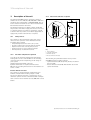
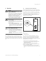
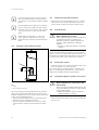
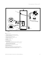
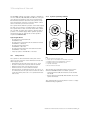
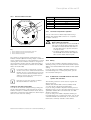
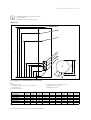
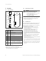
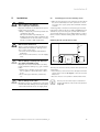
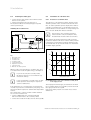
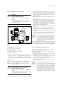
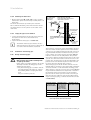
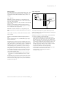
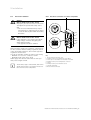
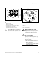
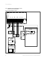
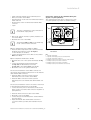
Installation 5
– eBUS-compatible Vaillant gas-fired wall-hung boiler
– Wiring via Control Center VR 65
– Primary heating circuit control via Vaillant dual-channel
eBUS controller
– Room heating control via Vaillant dual-channel eBUS
controller
– Y plan
Connect the cylinder to the standard cabling box
(S plan or Y plan hydraulics)
The cylinder thermostat can be connected to S plan
or Y plan hydraulics by means of standard cabling.
7
i
This type of installation is only permissible for
boilers which comply with G3
> Next to the domestic hot water cylinder, install the Control Center VR 65.
> Dismantle the cover of the VR 65.
i
1
The terminals NTC and CYL. of the VR 65 may
not be connected at the same time.
6
5
4
2
3
Option 1: Temperature sensor (NTC) on VR 65:
> Insert the VR 10 temperature sensor delivered with the
VR 65 into the immersion sleeve (2 ¬ fig. 5.7)
for the reheating circuit (NTC).
> Connect the temperature sensor (NTC) to the terminal
NTC of the VR 65.
Option 2: Cylinder thermostat to VR 65:
> Dismantle the cover of the cylinder thermostat (7 ¬ fig.
5.7).
> Connect the terminals 1 (cylinder thermostat)
(3 ¬ fig. 5.8) and C (reheating circuit TCO)
(5 ¬ fig. 5.8) to the terminal CYL. of the VR 65.
> Mount the cover for the cylinder thermostat.
Fig. 5.12 Connections of the cylinder thermostat and the thermal cut-out
Key
1 Cylinder thermostat
2 Cylinder thermostat protective earth terminal
3 Cylinder thermostat terminal 1
4 Primary heating circuit TCO protective earth terminal
5 Primary heating circuit TCO C terminal
6 Primary heating circuit TCO reset button
7 Primary heating circuit thermal cut-out (TCO)
The electrical installation of the eBUS connection is
described in the installation instructions for the Vaillant
dual-channel eBUS controller.
> Install the eBUS connection from the gas-fired
wall-hung boiler to the Control Center VR 65.
> Install the eBUS connection from the gas-fired
wall-hung boiler to the Vaillant dual-channel eBUS controller.
The electrical installation of the zone valves is described
in the installation instructions for the VR 65.
> Connect the 3-way valve for the heating circuit and hot
water circuit in accordance with connection diagram 2 (Y
plan hydraulics).
> Install the mains connection cable for the VR 65.
> Mount the covers of the VR 65.
> Connect the gas-fired wall-hung boiler and the VR 65 to
the power mains.
> Adjust the Vaillant dual-channel eBUS controller in
accordance with its operating and installation instructions.
Installation and maintenance instructions for uniSTOR 0020111105_00
27