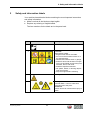
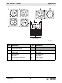
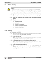
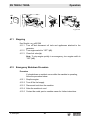
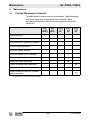
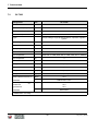
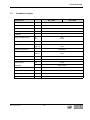
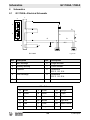
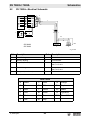
1
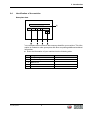
Operator´s manual Portable Generator GV 7000A GV 7003A 02.2013 5100004230en / 002 Manufacturer Wacker Neuson Produktion GmbH & Co. KG Preußenstraße 41 80809 München www.wackerneuson.com Tel.: +49-(0)89-354 02-0 Fax: +49-(0)89-354 02-390 Translation of the original operator's manual in German 1 Foreword 1 Foreword This operator's manual contains information and procedures for the safe operation and maintenance of your Wacker Neuson machine. In the interest of your own safety and to prevent accidents, you should carefully read through the safety information, familiarize yourself with it and observe it at all times. This operator's manual is not a manual for extensive maintenance and repair work. Such work should be carried out by Wacker Neuson service or authorized specialists. The safety of the operator was one of the most important aspects taken into consideration when this machine was designed. Nevertheless, improper use or incorrect maintenance can pose a risk. Please operate and maintain your Wacker Neuson machine in accordance with the instructions in this operator's manual. Your reward will be troublefree operation and a high degree of availability. Defective machine parts must be replaced immediately! Please contact your Wacker Neuson representative if you have any questions concerning operation or maintenance. All rights reserved, especially reproduction and distribution rights. Copyright 2013 Wacker Neuson Produktion GmbH & Co. KG No part of this publication may be reproduced in any form or by any means, electronic or mechanical, including photocopying, without the expressed written permission of Wacker Neuson. Any type of reproduction, distribution or storage on data media of any type and form not authorized by Wacker Neuson represents an infringement of copyright and will be prosecuted. We expressly reserve the right to make technical modifications – even without special notice – which aim at further improving our machines or their safety standards. 3 100_0000_0002.fm 2 Introduction 2 2.1 Introduction Means of representation for this operator's manual Warning symbols This operator's manual contains safety information of the categories: DANGER, WARNING, CAUTION, NOTICE. They should be followed to prevent danger to life and limb of the operator or damage to equipment and exclude improper service. DANGER This warning notice indicates immediate hazards that result in serious injury or even death. X Danger can be avoided by the following the actions mentioned. WARNING This warning notice indicates possible hazards that can result in serious injury or even death. X Danger can be avoided by the following the actions mentioned. CAUTION This warning notice indicates possible hazards that can result in minor injury. X Danger can be avoided by the following the actions mentioned. NOTICE This warning notice indicates possible hazards that can result in material damage. X Danger can be avoided by the following the actions mentioned. Notes Note: Complementary information will be displayed here. 100_0000_0003.fm 4 2 Introduction Instructions X This symbol indicates there is something for you to do. 1. Numbered instructions indicate that you have to carry out something in a defined sequence. 2.2 This symbol is used for lists. Wacker Neuson representative Depending on your country, your Wacker Neuson representative is your Wacker Neuson service, your Wacker Neuson affiliate or your Wacker Neuson dealer. You can find the addresses in the Internet at www.wackerneuson.com. The address of the manufacturer is located at the beginning of this operator's manual. 2.3 Described machine types This operator's manual is valid for different machine types from a product range. Therefore some figures can differ from the actual appearance of your machine. It is also possible that the descriptions include components which are not a part of your machine. Details for the described machine types can be found in the chapter Technical data. 5 100_0000_0003.fm 2 Introduction 2.4 Identification of the machine Nameplate data The nameplate lists information that uniquely identifies your machine. This information is needed to order spare parts and when requesting additional technical information. X Enter the information of your machine into the following table: Item 100_0000_0003.fm Designation Your information 1 Group and type 2 Construction year 3 Machine no. 4 Version no. 5 Item no. 6 EG-Konformitätserklärung Hersteller Wacker Neuson Produktion GmbH & Co. KG, Preußenstraße 41, 80809 München Produkt Produkt GV 7000A Produkt-Art Generator Produkt-Funktion Erzeugen von Strom Artikel-Nummer 0009348 Installierte Nutzleistung GV 7003A 0009353 5,47 kW 5100002155 5,60 kW Gemessener Schallleistungspegel 97 dB(A) Garantierter Schallleistungspegel 97 dB(A) Konformitätsbewertungsverfahren Nach 2000/14/EG, Anhang VIII. Benannte Stelle SNCH Société Nationale de Certification et ’Homologation, L-5230 Sandweiler Richtlinien und Normen Hiermit erklären wir, dass dieses Produkt den einschlägigen Bestimmungen und Anforderungen folgender Richtlinien und Normen entspricht: 2006/42/EG, 2006/95/EG, 2000/14/EG, 2004/108/EG, 2011/65/EU Bevollmächtigter für technische Unterlagen Axel Häret, Wacker Neuson Produktion GmbH & Co. KG, Preußenstraße 41, 80809 München München, 01.02.2013 Dr. Michael Fischer Geschäftsführer Technik und Innovation Original-Konformitätserklärung GV 7000A / 7003A Table of Contents Foreword 1 3 Safety Information 1.1 1.2 1.3 1.4 1.5 11 Signal Words Used in this Manual ..................................................... 11 Machine Description and Intended Use ............................................. 12 Safety Guidelines for Operating the Machine ..................................... 13 Operator Safety while Using Internal Combustion Engines ............... 16 Service Safety .................................................................................... 17 2 Labels 19 3 Lifting and Transporting 20 4 Operation 21 4.1 4.2 4.3 4.4 4.5 4.6 4.7 4.8 4.9 4.10 4.11 4.12 Preparing the Machine for First Use ................................................... 21 Power Requirements .......................................................................... 22 Installation .......................................................................................... 22 Generator Derating ............................................................................. 24 Grounding the Generator ................................................................... 25 Operating Heavy Loads ...................................................................... 25 Use of Extension Cords ...................................................................... 26 Control Panel ...................................................................................... 28 Before Starting ................................................................................... 30 Starting ............................................................................................... 30 Stopping ............................................................................................. 31 Emergency Shutdown Procedure ....................................................... 31 wc_bo5000187301_08TOC.fm 9 Table of Contents 5 GV 7000A / 7003A Maintenance 5.1 5.2 5.3 5.4 5.5 5.6 32 Periodic Maintenance Schedule ..........................................................32 Engine Oil ............................................................................................33 Servicing the Air Cleaner .....................................................................34 Spark Plug ...........................................................................................35 Engine Speed ......................................................................................36 Long-Term Storage .............................................................................37 6 Basic Troubleshooting 38 7 Technical Data 39 8 Schematics 42 8.1 8.2 GV 7000A—Electrical Schematic ........................................................42 GV 7003A—Electrical Schematic ........................................................43 10 wc_bo5000187301_08TOC.fm GV 7000A / 7003A 1 1.1 Safety Information Safety Information Signal Words Used in this Manual This manual contains DANGER, WARNING, CAUTION, NOTICE, and NOTE signal words which must be followed to reduce the possibility of personal injury, damage to the equipment, or improper service. This is the safety alert symbol. It is used to alert you to potential personal hazards. f Obey all safety messages that follow this symbol. DANGER DANGER indicates a hazardous situation which, if not avoided, will result in death or serious injury. f To avoid death or serious injury from this type of hazard, obey all safety messages that follow this signal word. WARNING WARNING indicates a hazardous situation which, if not avoided, could result in death or serious injury. f To avoid possible death or serious injury from this type of hazard, obey all safety messages that follow this signal word. CAUTION! CAUTION indicates a hazardous situation which, if not avoided, could result in minor or moderate injury. f To avoid possible minor or moderate injury from this type of hazard, obey all safety messages that follow this signal word. NOTICE: Used without the safety alert symbol, NOTICE indicates a situation which, if not avoided, could result in property damage. Note: A Note contains additional information important to a procedure. wc_si000530gb.fm 11 Safety Information 1.2 GV 7000A / 7003A Machine Description and Intended Use This machine is a portable electric power source. The Wacker Neuson Portable Generator consists of a tubular steel frame surrounding a fuel tank, a gasoline engine, a control panel, and an electric alternator. The control panel includes controls and receptacles. As the engine runs, the generator converts mechanical energy into electric power. The operator connects loads to the electric power receptacles. This machine is intended for the purpose of supplying electrical power to connected loads. Refer to the product specifications for the output voltage and frequency of this generator, and the maximum output power limit of this generator. This machine has been designed and built strictly for the intended use described above. Using the machine for any other purpose could permanently damage the machine or seriously injure the operator or other persons in the area. Machine damage caused by misuse is not covered under warranty. The following are some examples of misuse: • Connecting a load that has voltage and frequency requirements that are incompatible with the generator output • Overloading the generator with a load that draws excessive power during either continuous running or start-up • Operating the generator in a manner that is inconsistent with all federal, state and local codes and regulations • Using the machine as a ladder, support, or work surface • Using the machine to carry or transport passengers or equipment • Operating the machine outside of factory specifications • Operating the machine in a manner inconsistent with all warnings found on the machine and in the Operator’s Manual This machine has been designed and built in accordance with the latest global safety standards. It has been carefully engineered to eliminate hazards as far as practicable and to increase operator safety through protective guards and labeling. However, some risks may remain even after protective measures have been taken. They are called residual risks. On this machine, they may include exposure to: • Heat, noise, exhaust, and carbon monoxide from the engine • Fire hazards from improper refueling techniques • Fuel and its fumes • Electric shock and arc flash 12 wc_si000530gb.fm GV 7000A / 7003A • Safety Information Personal injury from improper lifting techniques To protect yourself and others, make sure you thoroughly read and understand the safety information presented in this manual before operating the machine. 1.3 Safety Guidelines for Operating the Machine DANGER Carbon monoxide. Using a generator indoors CAN KILL YOU IN MINUTES. Generator exhaust contains carbon monoxide (CO). This is a poison you cannot see or smell. If you can smell the generator exhaust, you are breathing CO. But even if you cannot smell the exhaust, you could be breathing CO. f NEVER use a generator inside homes, garages, crawlspaces, or other partly enclosed areas. Deadly levels of carbon monoxide can build up in these areas. Using a fan or opening windows and doors does NOT supply enough fresh air. f ONLY use a generator outside and far away from windows, doors, and vents. These openings can pull in generator exhaust. f Even when you use a generator correctly, CO may leak into the home. ALWAYS use a battery-powered or battery-backup CO alarm in the home. f If you start to feel sick, dizzy, or weak after the generator has been running, move to fresh air RIGHT AWAY. See a doctor. You could have carbon monoxide poison. WARNING Electrocution, fire, or explosion hazards. Improper connection of generator to a building’s electrical system can allow electrical current from the generator to backfeed into utility lines. This may result in electrocution, serious injury, or death to utility workers! f Comply with the connection requirements described below. Connection requirements The following are required when connecting the generator to a building’s electrical system. wc_si000530gb.fm • The generator must meet the power, voltage, and frequency requirements of the equipment in the building. • The generator power must be isolated from the utility power. • Connections from the generator to a building’s electrical system must be made by a qualified electrician. • Electrical connections must comply with all applicable laws and electrical codes. 13 Safety Information WARNING GV 7000A / 7003A Familiarity and proper training are required for the safe operation of the machine. Machines operated improperly or by untrained personnel can be hazardous. Read the operating instructions contained in this manual and the engine manual, and familiarize yourself with the location and proper use of all controls. Inexperienced operators should receive instruction from someone familiar with the machine before being allowed to operate it. Operator qualifications Only trained personnel are permitted to start, operate, and shut down the machine. They also must meet the following qualifications: • have received instruction on how to properly use the machine • are familiar with required safety devices The machine must not be accessed or operated by: • children • people impaired by alcohol or drugs Personal Protective Equipment (PPE) Wear the following Personal Protective Equipment (PPE) while operating this machine: • Close-fitting work clothes that do not hinder movement • Safety glasses with side shields • Hearing protection • Safety-toed footwear 1.3.1 NEVER operate the generator when open containers of fuel, paint, or other flammable liquids are near. 1.3.2 NEVER operate the generator, or tools attached to the generator, with wet hands. 1.3.3 NEVER use worn electrical cords. Severe electrical shock and equipment damage may result. 1.3.4 NEVER run the electrical cords under the generator, or over vibrating or hot parts. 1.3.5 NEVER enclose or cover the generator when it is in use or when it is hot. 1.3.6 NEVER overload the generator. The total amperage of the tools and equipment attached to the generator must not exceed the load rating of the generator. 1.3.7 NEVER operate the machine in snow, rain, or standing water. 1.3.8 NEVER allow untrained personnel to operate or service the generator. The generator set should be set up by a certified electrician. 14 wc_si000530gb.fm GV 7000A / 7003A Safety Information 1.3.9 Store the machine properly when it is not being used. The machine should be stored in a clean, dry location out of the reach of children. 1.3.10 Be sure the machine is on a firm, level surface and will not tip, roll, slide, or fall while operating. 1.3.11 ALWAYS transport the generator in an upright position. 1.3.12 ALWAYS keep the machine at least one meter (three feet) away from structures, buildings, and other equipment during use. 1.3.13 ALWAYS keep the area immediately surrounding and underneath the machine clean, neat, and free of debris and combustible materials. Make sure that the area overhead is clear of debris that could fall onto or into the machine or exhaust compartment. 1.3.14 ALWAYS remove all tools, cords, and other loose items from the generator before starting it. 1.3.15 DO NOT ground this generator. Generator vibration Generators vibrate in normal use. During and after the use of the generator, inspect the generator as well as extension cords and power supply cords connected to it for damage from vibration. wc_si000530gb.fm • Have damaged items repaired or replaced as necessary. • Do not use plugs or or cords that show signs of damage such as broken or cracked insulation or damaged blades. 15 Safety Information 1.4 GV 7000A / 7003A Operator Safety while Using Internal Combustion Engines WARNING Internal combustion engines present special hazards during operation and fueling. Failure to follow the warnings and safety standards could result in severe injury or death. f Read and follow the warning instructions in the engine owner’s manual and the safety guidelines below. DANGER f Carbon monoxide. Using a generator indoors CAN KILL YOU IN MINUTES. Generator exhaust contains carbon monoxide (CO). This is a poison you cannot see or smell. If you can smell the generator exhaust, you are breathing CO. But even if you cannot smell the exhaust, you could be breathing CO. Refueling safety When refueling the engine: • Do not smoke. • Do not refuel if the generator is sitting in a truck fitted with a plastic bed liner. Static electricity can ignite the fuel or fuel vapors. • Do not refuel a hot or running engine. • Do not refuel the engine near an open flame. When refueling the engine, always: • Refill the fuel tank in a well-ventilated area. • Replace the fuel tank cap after refueling. Operating safety When operating the generator: • Check the fuel lines and the fuel tank for leaks and cracks before starting the engine. • Do not run the machine if fuel leaks are present or the fuel lines are loose. • Do not run the engine near open flames. • Do not start the engine if fuel has spilled or a fuel odor is present. Move the generator away from the spill and wipe the generator dry before starting. • Do not smoke while operating the machine. 16 wc_si000530gb.fm GV 7000A / 7003A 1.5 Safety Information Service Safety WARNING Poorly maintained equipment can become a safety hazard! In order for the equipment to operate safely and properly over a long period of time, periodic maintenance and occasional repairs are necessary. If the generator is experiencing problems or is being serviced, attach a “DO NOT START” sign to the control panel to notify other people of its condition. Personal Protective Equipment (PPE) Wear the following Personal Protective Equipment (PPE) while servicing or maintaining this machine: • Close-fitting work clothes that do not hinder movement • Safety glasses with side shields • Hearing protection • Safety-toed footwear In addition, before servicing or maintaining the machine: wc_si000530gb.fm • Tie back long hair. • Remove all jewelry (including rings). 1.5.1 Do not use gasoline or other types of fuels or flammable solvents to clean parts, especially in enclosed areas. Fumes from fuels and solvents can become explosive. 1.5.2 DO NOT attempt to clean or service the machine while it is running. 1.5.3 Do not modify the machine without the express written approval of the manufacturer. 1.5.4 DO NOT allow water to accumulate around the base of the machine. If water is present, move the machine and allow the machine to dry before servicing. 1.5.5 DO NOT service the machine if your clothing or skin is wet. 1.5.6 DO NOT allow untrained personnel to service this equipment. Only trained electrical technicians should be allowed to service the electrical components of this equipment. 1.5.7 Keep the machine clean and labels legible. Replace all missing and hard-to-read labels. Labels provide important operating instructions and warn of dangers and hazards. 1.5.8 ALWAYS replace the safety devices and guards after repairs and maintenance. 1.5.9 ALWAYS let the engine cool before transporting or servicing the machine. 1.5.10 ALWAYS keep hands, feet, and loose clothing away from the moving parts on the generator and engine. 17 Safety Information GV 7000A / 7003A 1.5.11 ALWAYS turn the engine off before servicing the machine. If the engine has electric start, disconnect the negative terminal on the battery before servicing the machine. 1.5.12 ALWAYS keep the fuel lines in good condition and properly connected. Leaking fuel and fumes are extremely explosive. 1.5.13 When replacement parts are required for this machine, use only Wacker Neuson replacement parts or those parts equivalent to the original in all types of specifications, such as physical dimensions, type, strength, and material. 18 wc_si000530gb.fm 2 Safety and information labels 2 Safety and information labels Your machine has adhesive labels containing the most important instructions and safety information. Make sure that all the labels are kept legible. Replace any missing or illegible labels. The item numbers for the labels are in the parts book. Item 100_0402_ls_0004.fm Label Description 1 Guaranteed sound power level. 2 DANGER! Asphyxiation hazard. Engines emit carbon monoxide. Do not run the machine indoors or in an enclosed area. NEVER use inside a home or garage, EVEN IF doors and windows are open. Only use OUTSIDE and far away from windows, doors, and vents. Read the Operator’s Manual. No sparks, flames, or burning objects near the machine. Stop the engine before refueling. 3 Warning of hot surface. 4 Warning of hot surface. Potential Earth - Connect cable from grounding rod to this point. WARNING! Electric shock can cause serious injury or death. 19 Lifting and Transporting 3 GV 7000A / 7003A Lifting and Transporting Lifting the Machine This generator, while compact, is heavy enough to cause injury if proper lifting techniques are not used. Observe the following guidelines when lifting the generator. • Do not attempt to lift and carry the generator unassisted. Use appropriate lifting equipment such as slings, chains, hooks, ramps, or jacks. • Make sure lifting equipment is attached securely and has enough weight-bearing capacity to lift or hold the generator safely. • Remain aware of the location of other people nearby when lifting the generator. Transporting the Machine Observe the following guidelines when transporting the generator to and from the job site. • Allow the engine to cool before transporting the generator. • Drain the fuel tank. • Close the fuel valve. • Ensure that the generator is securely strapped down in the transport vehicle to prevent it from sliding or tipping. • Do not refuel the generator in or on the transport vehicle. Move the generator to its operating location and then fill the fuel tank. 20 wc_tx001617gb.fm GV 7000A / 7003A 4 4.1 Operation Operation Preparing the Machine for First Use Preparing for first use To prepare your machine for first use: 4.1.1 Make sure all loose packaging materials have been removed from the machine. 4.1.2 Check the machine and its components for damage. If there is visible damage, do not operate the machine! Contact your Wacker Neuson dealer immediately for assistance. 4.1.3 Take inventory of all items included with the machine and verify that all loose components and fasteners are accounted for. 4.1.4 Attach component parts not already attached. 4.1.5 Add fluids as needed and applicable, including fuel, engine oil, and battery acid. 4.1.6 Move the machine to its operating location. DANGER Carbon monoxide. Using a generator indoors CAN KILL YOU IN MINUTES. Generator exhaust contains carbon monoxide (CO). This is a poison you cannot see or smell. If you can smell the generator exhaust, you are breathing CO. But even if you cannot smell the exhaust, you could be breathing CO. f NEVER use a generator inside homes, garages, crawlspaces, or other partly enclosed areas. Deadly levels of carbon monoxide can build up in these areas. Using a fan or opening windows and doors does NOT supply enough fresh air. f ONLY use a generator outside and far away from windows, doors, and vents. These openings can pull in generator exhaust. f Even when you use a generator correctly, CO may leak into the home. ALWAYS use a battery-powered or battery-backup CO alarm in the home. f If you start to feel sick, dizzy, or weak after the generator has been running, move to fresh air RIGHT AWAY. See a doctor. You could have carbon monoxide poison. Using gasoline / ethanol blends This portable generator is not for use with gasoline / ethanol blends with over 15% ethanol. wc_tx001624gb.fm 21 Operation 4.2 GV 7000A / 7003A Power Requirements Wacker Neuson generator Model GV 7000A is designed to operate single-phase, 50 Hertz appliances running at 230 VAC. Model GV 7003A is designed to operate single phase, 50 Hertz appliances running at 230VAC and/or three-phase, 50 Hertz appliances running at 400VAC. Both single and three phase sides of the generator may be run at the same time. NOTICE: Do not exceed the power output of the generator. Damage to tools or generator will occur. See Technical Data. Check the nameplate or label provided on tools and appliances to make sure their power requirements are met by the power output of the generator. If the wattage is not given for a particular tool or appliance, contact the tool manufacturer for wattage requirements. Some appliances and tools require a surge of current when starting. This means that the amount of power needed to initially start the equipment is larger than the power required to keep it running. The generator must be capable of supplying this "surge" current. Other types of appliances require more power than is actually stated on their nameplate. The information in “Approximate Starting Power Requirements” is offered only as a general guideline to help you determine power requirements for different types of equipment. Check with your nearest Wacker Neuson dealer, or contact the manufacturer or dealer of the tool or appliance, if you have questions regarding power requirements. NOTICE: DO NOT exceed the rated current limit of any receptacle. NOTICE: If a tool or appliance does not reach full speed within a few seconds after it is switched on, turn it off immediately to avoid damage. Approximate Starting Power Requirements • Incandescent lights and appliances such as irons and hot plates, which use a resistive-type heating element, require the same wattage to start and run as is stated on their nameplates. • Fluorescent and mercury lamps require 1.2–2 times their stated wattage to start. • Electrical motors and many types of electrical tools often require a large starting current. The amount of starting current depends on the type of motor and its use. • Most electrical tools require 1.2–3 times their stated wattage for starting. • Loads such as submersible pumps and air compressors require a very large force to start. They need as much as 3–5 times the wattage stated on the nameplate in order to start. 22 wc_tx001624gb.fm GV 7000A / 7003A Operation If the wattage is not given for a particular tool or appliance, it can be calculated by multiplying its voltage and amperage requirements: Single Phase: VOLTS x AMPS = WATTS Three Phase: VOLTS x AMPS x 1.732 x 0.8 = WATTS 4.3 Installation Place the generator in an area where it will not be exposed to rain, snow, or direct sunlight. Make sure it is positioned on firm, level ground, so it will not slide or shift. Position the engine exhaust away from areas where people may be present. The surrounding area must be free from water and moisture. All components must be protected from excessive moisture. wc_tx001624gb.fm 23 Operation 4.4 GV 7000A / 7003A Generator Derating All generators are subject to derating for altitude and temperature. Internal combustion engines, unless modified, run less efficiently at higher altitudes due to the reduction of air pressure. This translates into a lack of power and thus reduction in generator output. Temperature affects both engine and generator performance. As temperature increases, an engine will run less efficiently and more resistance will be found in electrical components. Therefore, as the temperature increases, the output of the generator decreases. Altitude also affects the cooling capacity of air—the higher the altitude the less dense the air is and thus the lower its ability to transfer heat. For every increase in altitude of 500 m (1650 ft.) above 1000 m (3300 ft.), the output of the generator will be reduced by 3%. For every increase of 5° C (9° F) in ambient temperature above 40° C (104° F), the output of the generator will be reduced by 3%. Use the tables shown for altitude and temperature deration factors. It may be necessary to consider both altitude and ambient temperature deration factors to determine true generator output. Ambient Temp. °C (°F) Derate Factor 45 (113) 3% 0.97 50 (122) 6% 0.94 55 (131) 9% 0.91 60 (140) 12 % 0.88 Altitude m (ft.) Derate Factor 1500 (4900) 3% 0.97 2000 (6600) 6% 0.94 2500 (8200) 9% 0.91 3000 (9900) 12 % 0.88 3500 (11500) 15 % 0.85 4000 (13100) 18 % 0.82 24 wc_tx001624gb.fm GV 7000A / 7003A 4.5 Operation Grounding the Generator CAUTION The neutral of this machine is not connected to ground. Under standard operating conditions, do not connect the frame PE stud to earth ground. Refer to local codes if machine is used to power a building or similar distribution system. wc_gr001286 4.6 Operating Heavy Loads Limit operations requiring the maximum rated output of the generator to 20–30 minutes. For continuous operation, do not exceed the continuous rated output of the generator. Refer to the Generator Technical Data specification chart. wc_tx001624gb.fm 25 Operation 4.7 GV 7000A / 7003A Use of Extension Cords WARNING When a long extension cord is used to connect an appliance or tool to the generator, a voltage loss occurs—the longer the cord, the greater the voltage loss. This results in less voltage being supplied to the appliance or tool and increases the amount of current draw or reduces performance. A cord with a larger cross section will reduce the voltage loss. NOTICE: Operating equipment at low voltage can cause it to overheat. Use only tough rubber-sheathed cable in accordance with IEC 245-4. Damaged cords can cause electric shock. Electric shock can cause serious injury or death. DO NOT use worn, bare, or frayed cords. Replace damaged cords immediately. Do not exceed the rating of the cord. Contact the cord manufacturer if in doubt about cord use. Choose the cord size from the Minimum Extension Cord Size Table or calculate minimum cord size using the Minimum Extension Cord Size Graph. The X axis of the graph represents A x m (Ampere x meter) values. The Y axis represents wire size in mm2. Multiply the operating current for the load in amps (A) by the desired extension cord length in meters (m). Find the result along the X axis. Move up the graph until you reach the appropriate sloped line for your application. Move to the Y axis; this is the recommended minimum cord size. Example: For a 3-phase, 400V application, if the operating current for the load is 15 A, and the desired extension cord length is 100 m, then: 15 A x 100 m = 1500 A x m. 1500 A x m = 2.5 mm2. 26 wc_tx001624gb.fm GV 7000A / 7003A Operation Minimum Extension Cord Size Table Minimum Extension Cord Size Amp Rating 230V/1~/50Hz 400V/3~/50Hz Length m Length m 25 50 100 200 25 50 100 200 Cross sectional area of wire in mm2 2 1.5 1.5 1.5 1.5 1.5 1.5 1.5 1.5 4 1.5 1.5 1.5 2.5 1.5 1.5 1.5 1.5 6 1.5 1.5 1.5 4 1.5 1.5 1.5 2.5 8 1.5 1.5 2.5 6 1.5 1.5 1.5 2.5 10 1.5 1.5 4 6 1.5 1.5 1.5 4 15 1.5 2.5 4 10 1.5 1.5 2.5 6 20 1.5 4 6 16 1.5 1.5 4 6 30 2.5 4 10 25 1.5 2.5 6 10 40 4 6 16 --- 1.5 4 6 --- Minimum Extension Cord Size Graph 25 z V 50 H 0 3 2 1~ 16 10 mm 2 z V 50 H 0 0 4 3~ 6 4 2.5 1.5 0 1000 2000 3000 Axm wc_tx001624gb.fm 27 4000 5000 6000 Operation 4.8 GV 7000A / 7003A Control Panel See graphic: wc_gr001275 and wc_gr001369 The circuit breaker protects the generator from severe overloads or short circuits. If the circuit breaker opens, turn the engine off immediately and determine the cause before restarting. Check the appliances and tools attached to the generator for defects and make sure their power requirements do not exceed the power rating of the generator or the current limit of the receptacles. Note: Enlargements of receptacles show protective covers removed for identification purposes only. Never remove protective covers. d1 d2 d3 d4 c b a GV 7000A wc_gr001275 Ref. Description a Main circuit breaker - 22 A c CEE receptacle IP44 230 V, 32 A d1 d3 Ref. Description b Main circuit breaker - 12 A Schuko IP44 (CEE 7) receptacle 230 V, 16 A d2 CEE receptacle IP44 2P+E 230 V, 16 A Swiss receptacle 230 V, 16 A d4 French receptacle 230 V, 16 A 28 wc_tx001624gb.fm GV 7000A / 7003A Operation g1 f2 f1 g2 e f4 f3 GV 7003A wc_gr001370 Ref. Description e Main circuit breaker 10 A, 12 A, 10 A 3-Pole f1 Schuko IP54 (CEE 7) receptacle 230V, 16 Amp f2 CEE receptacle IP44 2P+E 230 V, 16 A f3 Swiss receptacle 230 V, 16 A f4 French receptacle 230 V, 16 A g1 CEE receptacle IP44 3P+N+E 400 V, 3 Ø, 16 A g2 Swiss receptacle 400 V, 3 Ø, 16 A wc_tx001624gb.fm Ref. 29 Description Operation 4.9 GV 7000A / 7003A Before Starting DANGER f Carbon monoxide. Using a generator indoors CAN KILL YOU IN MINUTES. Generator exhaust contains carbon monoxide (CO). This is a poison you cannot see or smell. If you can smell the generator exhaust, you are breathing CO. But even if you cannot smell the exhaust, you could be breathing CO. 4.10 4.9.1 Read and understand safety and operating instructions at beginning of this manual. 4.9.2 Read and understand the meanings of all warning and operating labels. 4.9.3 Check: • oil level in engine. • fuel level. • condition of air cleaner. • tightness of external fasteners. • condition of fuel lines. Starting See Graphic: wc_gr001299 4.10.1 Disconnect all loads from the generator and place main circuit breaker in open position (e2) (GV 5003A, GV 7003A). 4.10.2 Open fuel valve (a). Note: If engine is cold, move choke (b) to closed position—pull out.. If engine is hot, set choke to open position—push in. 4.10.3 Turn engine switch to "ON" (c1) and pull starter rope (d). Note: If the oil level in the engine is low, the engine will not start. If this happens, check oil level and add oil as needed. 4.10.4 Open choke as engine warms (b). 4.10.5 Place main circuit breaker in closed position (e1) (GV 5003A, GV 7003A). Allow the engine to warm up for a few minutes before attaching loads. 30 wc_tx001624gb.fm GV 7000A / 7003A e2 Operation b c2 c1 e1 d a wc_gr001299 4.11 Stopping See Graphic: wc_gr001299 4.11.1 Turn off and disconnect all tools and appliances attached to the generator. 4.11.2 Turn engine switch to “OFF” (c2). 4.11.3 Close fuel valve (a). Note: To stop engine quickly in an emergency, turn engine switch to “OFF” (c2). 4.12 Emergency Shutdown Procedure Procedure If a breakdown or accident occurs while the machine is operating, follow the procedure below: 4.12.1 Stop the engine. 4.12.2 Turn off the fuel supply. 4.12.3 Disconnect tools from the machine. 4.12.4 Allow the machine to cool. 4.12.5 Contact the rental yard or machine owner for further instructions. wc_tx001624gb.fm 31 Maintenance 5 5.1 GV 7000A / 7003A Maintenance Periodic Maintenance Schedule The table below lists basic machine maintenance. Tasks designated with check marks may be performed by the operator. Tasks designated with square bullet points require special training and equipment. Daily before starting Check fuel level. 3 Check engine oil level. 3 Inspect air filter. Replace as needed.* 3 Check external hardware. 3 After first 20 hrs. Clean air cleaner element.* Every 50 hrs. Every 100 hrs. Every 300 hrs. 3 Inspect shockmounts for damage. 3 Change engine oil.* Check and clean spark plug. Check and adjust valve clearance. Clean fuel tank.* Check condition of fuel line. Replace when necessary. *Service more frequently in dusty conditions. 32 wc_tx001625gb.fm GV 7000A / 7003A 5.2 Maintenance Engine Oil See Graphic: wc_gr000022 5.2.1 Drain the oil while the engine is still warm. 5.2.2 Remove the oil filler plug (a) and the drain plug (b) to drain the oil. Note: In the interests of environmental protection, place a plastic sheet and a container under the machine to collect any liquid that drains off. Dispose of this liquid in accordance with environmental protection legislation. 5.2.3 Install the drain plug. 5.2.4 Fill the engine crankcase with the recommended oil up to the level of the plug opening (c). See section Technical Data for oil quantity and type. 5.2.5 Install the oil filler plug. wc_gr000022 wc_tx001625gb.fm 33 Maintenance 5.3 GV 7000A / 7003A Servicing the Air Cleaner See Graphic: wc_gr0001287 The engine is equipped with a single element air cleaner. Service air cleaner frequently to prevent carburetor malfunction. NOTICE: NEVER run the engine without the air cleaner. Severe engine damage will occur. NEVER use gasoline or other types of low flashpoint solvents for cleaning the air cleaner. A fire or explosion could result. WARNING To service: 5.3.1 Release latches (a) on the top and bottom of the air cleaner cover (b), and remove the cover. 5.3.2 Check the filter element (c) to be sure it is in good condition. Replace damaged filters. 5.3.3 Wash filter element in solution of mild detergent and warm water. Rinse thoroughly in clean water. Allow element to dry thoroughly. Soak element in clean engine oil and squeeze out excess oil. 5.3.4 Reinstall the element and air cleaner cover. a b c wc_gr001287 34 wc_tx001625gb.fm GV 7000A / 7003A 5.4 Maintenance Spark Plug See Graphic: wc_gr000028 Clean or replace the spark plug as needed to ensure proper operation. Refer to your engine operator’s manual. The muffler becomes very hot during operation and remains hot for a while after stopping the engine. Do not touch the muffler while it is hot. WARNING Note: Refer to section “Technical Data” for the recommended spark plug type and the electrode gap setting. 5.4.1 Remove the spark plug and inspect it. 5.4.2 Replace the spark plug if the insulator is cracked or chipped. 5.4.3 Clean the spark plug electrodes with a wire brush. 5.4.4 Set the electrode gap (a). 5.4.5 Tighten the spark plug securely. NOTICE: A loose spark plug can become very hot and may cause engine damage. wc_tx001625gb.fm 35 Maintenance 5.5 GV 7000A / 7003A Engine Speed See Graphic: wc_gr001300 Generators require a fixed engine speed to maintain the correct voltage. Engine speed is controlled by a governor which automatically adjusts to varying loads on the engine to maintain a constant speed of 3000 rpm. There is no throttle control. To set the engine to the proper speed: Turn the speed adjusting screw (a) in or out to obtain a no-load speed of 3100 rpm. NOTICE: Setting the engine speed too high or too low may damage tools and other appliances attached to the generator. Adjust engine to the no load or idle speed per the Technical Data. 5.5.1 Start the engine and allow it to warm up to normal operating temperature. 5.5.2 Turn the throttle stop screw (a) in to increase speed, out to decrease speed. Make sure the throttle lever is touching the stop screw before measuring rpm. a wc_gr001300 36 wc_tx001625gb.fm GV 7000A / 7003A 5.6 Maintenance Long-Term Storage Before storing generator for a long period of time: 5.6.1 Turn the engine fuel valve to the OFF position. 5.6.2 Disconnect the fuel line from the carburetor. Place open end of fuel line into a suitable container and open fuel valve to drain fuel from tank. Gasoline is extremely flammable. Drain fuel tank in a well ventilated area. DO NOT drain tank in an area with flames or sparks. WARNING wc_tx001625gb.fm 5.6.3 Loosen the drain screw on the carburetor and drain any remaining fuel from carburetor. 5.6.4 Change the engine oil. 5.6.5 Remove the spark plug and pour approximately 30 ml (1 ounce) of clean engine oil into the cylinder. Crank the engine a few turns to distribute the oil to the inside of the cylinder walls. 5.6.6 Pull the starter rope slowly until resistance is felt and leave handle in this position. This ensures that the intake and exhaust valves are closed. 5.6.7 Store generator in a clean, dry area. 37 Basic Troubleshooting 6 GV 7000A / 7003A Basic Troubleshooting Problem / Symptom Reason / Remedy If engine doesn't start, check that: • Engine switch is on "Start". • Fuel valve is open. • Fuel tank has fuel. • Choke lever is in correct position. Choke should be closed when starting a cold engine. • All loads are disconnected from generator. • Spark plug is in good condition. • Spark plug cap is tight. • Engine oil level is adequate. If engine starts but there is no power at receptacles, check that: • Circuit breaker is closed. If engine starts but runs erratically, check: • Condition of air filter. • Wiring from generator to receptacles is tight. • Condition of spark plug and plug cap. • Freshness of fuel. 38 wc_tx001618gb.fm 7 Technical data 7 7.1 Technical data GV 7000 Designation Unit Item no. GV 7000A GV 7000A 0009348 0009353 Maximum Output (LTP) kVA 7,2 Continuous Output (COP) kVA 6,0 Net installed power kW 5,47 Type Single voltage, single phase Brushless, capacitor regulator system AC Voltages Available V 230 Phase ~ 1 Frequency Hz 50 Power Factor cos 0,9 AC receptacles 230V 16A 1~ CEE7/4, 230V 32A 1~ CEE 230V 16A 1~ CEE7/5, 230V 32A 1~ CEE AC receptacles qty 2 Main Circuit Breaker A 25 Length mm (in) 729 (28.7) Width mm (in) 500 (19.7) Height mm (in) 536 (21.1) Weight kg (lb) 76,0 (167.6) Sound pressure level LpA * dB(A) 77,0 Standard Sound power level LWA measured guaranteed DIN EN ISO 11201 dB(A) 97,0 97,0 Standard 2000/14/EC * Measured in 4 m away. 100_0402_td_0004.fm 39 7 Technical data 7.2 GV 7003 Designation Unit GV 7003A Item no. 5100002155 Maximum Output (LTP) kVA 8,3 Continuous Output (COP) kVA 7,0 Net installed power kW 5,60 Type Single voltage, single phase Brushless, capacitor regulator system AC Voltages Available V 230 / 400 Phase ~ 1~ + 3~ Frequency Hz 50 Power Factor cos 0,8 AC receptacles 230V 16A 1~ CEE, 400V 16A 3~ CEE, 230V 16A 1~ CEE7/4 AC receptacles qty 3 Main Circuit Breaker A 25 Length mm (in) 729 (28.7) Width mm (in) 500 (19.7) Height mm (in) 536 (21.7) Weight kg (lb) 81,0 (198.9) Sound pressure level LpA * dB(A) 77,0 Standard Sound power level LWA measured guaranteed DIN EN ISO 11201 dB(A) 97,0 97,0 Standard 2000/14/EC * Measured in 4 m away. 40 100_0402_td_0004.fm 7 Technical data 7.3 Combustion engine Designation GV 7000A Manufacturer GV 7003A Honda Engine type GX390RT2 Combustion method Four-cycle Cooling Air cooling Cylinder 1 Engine displacement cm3 (in3) 389 (23.7) Fuel type Fuel consumption Ottokraftstoff l/h (gph us) 2.1 (0.6) Mixture preparation Tank capacity Carburetor l (gal us) 11,0 (2.9) Oil specification SAE 10W-40 Rated output kW 7.0 Rated speed rpm 3,600 Standard Upper idling speed SAE J1349 rpm 3,000 Type of spark plug Spark plug air gap NGK BPR5ES mm (in) 0.7 (0.027) Starter type 100_0402_td_0004.fm Recoil starter 41 Schematics 8 GV 7000A / 7003A Schematics 8.1 GV 7000A—Electrical Schematic 1 4 5 7 6 R 5 R 6 7 G G 2 R G/Y G/Y 3 8 9 GV 7000A Ref. wc_gr001302 Description Ref. Description 1 Main Windings 6 Surge Absorber 2 Auxiliary Winding 7 Circuit Breaker 3 Capacitor 8 Receptacle 230 V, 1 Ø, 16 A 4 Rotor Windings 9 Receptacle 230 V, 1 Ø, 32 A 5 Diode Wire Colors B Black V Violet Or Orange G Green W White Pr Purple L Blue Y Yellow Sh Shield P Pink Br Brown LL Light Blue R Red Cl Clear G/Y T Tan Gr Gray 42 Green/Yellow wc_tx001619gb.fm GV 7000A / 7003A 8.2 Schematics GV 7003A—Electrical Schematic 5 1 Br L Br Br W1V1 U1 V2 U2 W2 B W Br W Br B L W Br B B W 7 B ROTOR R 4 6 3 B W Br L W L Br G/Y 10 L Br GND GV 5003A GV 7003A 1~230V/16A 8 3~400V/16A 9 wc_gr001249 Ref. Description Ref. Description 1 Main Windings 6 Terminal board 2 Auxiliary Winding 7 Circuit Breaker 3 Regulator (Rectifier) 8 Receptacle 230 V, 1 Ø, 16 A 4 Rotor Windings 9 Receptacle 400 V, 3 Ø, 16 A 5 Compound (transformer) 10 Brushes Wire Colors wc_tx001619gb.fm B Black V Violet Or Orange G Green W White Pr Purple L Blue Y Yellow Sh Shield P Pink Br Brown LL Light Blue R Red Cl Clear G/Y T Tan Gr Gray 43 Green/Yellow