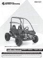
1
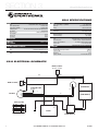
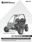
Book 2 of 2
K
BLAC
BLUE
E
WHIT
s
Curntitroller
o
C g
Plu
N
GREE
BF1
RED
E
WHIT
K
BLAC
K
BLAC
RED
r
BLUE
BLUE e/Regen
Driv
rse
Revfeety
Sa itch
Sw
N
BLUE
GREE
OW
ard
Forwafety
S itch
Sw
YELL
BLUE
K
BLAC
HITE
ry
Battceharge
s
i
D icator
Ind
Fus e
BLUE
10A
ter
ome
nti
Pote
OW
YELL
acto
Cont
GREY
BLUE
N
BROW
K
BLAC
W
R
R
F/N/
ch
Swit
N
F
N
GREE
RED
MODEL 5210 / AGES 13+ / 24 MPH MAX SPEED
5210 208cc FUN KART OWNER’S MANUAL / PARTS GUIDE
15362R1
THIS VEHICLE IS FOR OFF-ROAD USE ONLY THIS VEHICLE IS NOT DESIGNED FOR USE ON RENTAL TRACKS OR RACING
BEFORE OPERATING THIS VEHICLE, THE OWNER AND EACH OPERATOR MUST UNDERSTAND THIS VEHICLE WAS NOT DESIGNED OR MANUFACTURED TO MEET SPECIFICATIONS FOR USE ON PUBLIC ROADS,
STREETS, HIGHWAYS AND THOROUGHFARES. THE OWNER AND EACH OPERATOR MUST READ AND UNDERSTAND ALL THE INSTRUCTIONS FOR PROPER ASSEMBLY AND SAFE OPERATION, AS WELL AS THE
INSTRUCTIONS CONCERNING THE ENGINE AND ALL OTHER PORTIONS OF THE VEHICLE. CHILDREN MUST BE 13+ YEARS OF AGE FOR THIS VEHICLE AND SUPERVISED BY AN ADULT AT ALL TIMES WHEN USING
THIS FUN KART. SPEED REDUCTION KITS ARE AVAILABLE FOR ALL VEHICLES. THIS VEHICLE IS NOT A TOY.
limited warranty
American SportWorks (hereinafter referred to as “ASW”) hereby warrants to the original purchaser that the frame components of new ASW fun karts will be
free from defects in material and workmanship. The period of warranty is thirty (30) days from date of purchase for the component parts (except as noted
below), ninety (90) days from the date of purchase for the frame, and one (1) year from date of purchase on select engines. Some engines may carry a separate
manufacturer’s warranty and are not covered by this ASW warranty. ASW, if notified of a defect in material or workmanship during the period of warranty,
will repair or replace, at its option, defective parts at no charge, other than the reasonable cost for the transportation of the component(s). ASW will also agree
to pay reasonable charges for labor, if necessary, to perform a warranty repair. Proof of Purchase must be provided to an approved ASW service center before
any warranty work is performed.
The original purchaser must operate the vehicle and maintain the vehicle in accordance with the instructions provided in the Operator’s Manual, the
supplements hereto, and labels affixed to the vehicle. Additionally, within (10) days of the discovery of an alleged defect, the original purchaser must contact
ASW’s Customer Service Department at 1-800-643-7332, 4404 Engle Ridge Drive, Fort Wayne, IN 46804 or via the internet at www.amsportworks.com.
The repair or replacement of any part or parts under this Limited Warranty shall not extend the term of the warranty beyond the original term as set forth
above.
General Exclusions: This limited warranty does not cover component failure or damage caused by any of the following: abnormal strain or stress, neglect;
abuse; improper assembly of components which were supplied in the factory sealed carton after the vehicle left ASW; improper maintenance, improper use of
the vehicle, including, but not limited to racing, jumping, stunt driving, or any other uses prohibited by the Operator’s Manual. Additionally, this warranty
does not cover component failure or damage to vehicles which are leased or rented, or vehicles which are used at a concession track.
Specific Exclusions: This limited warranty does not apply to components, which are subject to normal wear and tear. These items include, but are not limited
to, the tires, brakes, throttle, shift and brake cables, drive belt, the torque converter system, chain, seat, lights, fasteners, decals, or cosmetic body panels and
natural discoloration of material due to ultraviolet light. Downtime, pick-up and delivery charges are not covered by this warranty. This warranty does not
apply to select engines covered by a separate manufacturer’s warranty.
ASW MAKES NO OTHER WARRANTY OF ANY KIND, EXPRESSED OR IMPLIED. ALL WARRANTIES OF MERCHANTABILITY AND
FITNESS FOR A PARTICULAR PURPOSE WHICH EXCEED THE OBLIGATIONS AND TIME LIMITATIONS SPECIFIED IN THE
WARRANTY ABOVE ARE HEREBY DISCLAIMED BY ASW AND EXCLUDED FROM THIS WARRANTY. ADDITIONALLY, THIS WARRANTY
EXCLUDES ANY INCIDENTAL OR CONSEQUENTIAL DAMAGES, INCLUDING BUT NOT LIMITED TO LOSS OF USE. SOME STATES
DO NOT ALLOW A MANUFACTURER TO EXCLUDE OR LIMIT INCIDENTAL OR CONSEQUENTIAL DAMAGES AND, THEREFORE,
THE ABOVE EXCLUSION MAY NOT APPLY TO YOU.
SOME STATES DO NOT ALLOW LIMITATIONS ON HOW LONG AN IMPLIED WARRANTY WILL LAST. IT IS POSSIBLE THAT THE
ABOVE LIMITATION MAY NOT APPL Y TO YOU. THIS WARRANTY GIVES YOU SPECIFIC LEGAL RIGHTS, AND YOU MAY ALSO HAVE
OTHER LEGAL RIGHTS, WHICH VARY, FROM STATE TO STATE.
VEHICLE IDENTIFICATION NUMBER
Record the Vehicle Identification Number (VIN) and Model number of your American SportWorks Fun Kart
below for service and insurance records. The VIN can be found on the crossbar, behind the seat. The
Model number is located on the SKU decal near the floorboard.
VIN
MODEL
i
TABLE OF CONTENTS
ASW Limited Warranty . . . . . . . . . . . . . . . . . . . . . . . . . . . . . . . . . . . . . . . . . . . . . . . . . . . . . . . . . . . . . . . . . . . i
SECTION 1 INTRODUCTION
Forward . . . . . . . . . . . . . . . . . . . . . . . . . . . . . . . . . . . . . . . . . . . . . . . . . . . . . . . . . . . . . . . . . . . . . . . . . . . . . . 1
Emissions Warranty . . . . . . . . . . . . . . . . . . . . . . . . . . . . . . . . . . . . . . . . . . . . . . . . . . . . . . . . . . . . . . . . . . . . . 1
Cell Phone Use . . . . . . . . . . . . . . . . . . . . . . . . . . . . . . . . . . . . . . . . . . . . . . . . . . . . . . . . . . . . . . . . . . . . . . . . 1
SECTION 2 OPERATION
Kart Operation . . . . . . . . . . . . . . . . . . . . . . . . . . . . . . . . . . . . . . . . . . . . . . . . . . . . . . . . . . . . . . . . . . . . . . . . . 2
Kart Features and Locations . . . . . . . . . . . . . . . . . . . . . . . . . . . . . . . . . . . . . . . . . . . . . . . . . . . . . . . . . . . . . . 4
SECTION 3 SERVICE / GENERAL MAINTENANCE
Replacement Parts . . . . . . . . . . . . . . . . . . . . . . . . . . . . . . . . . . . . . . . . . . . . . . . . . . . . . . . . . . . . . . . . . . . . . 5
Air Cleaner . . . . . . . . . . . . . . . . . . . . . . . . . . . . . . . . . . . . . . . . . . . . . . . . . . . . . . . . . . . . . . . . . . . . . . . . . . . . 5
Engine lubrication . . . . . . . . . . . . . . . . . . . . . . . . . . . . . . . . . . . . . . . . . . . . . . . . . . . . . . . . . . . . . . . . . . . . . . 5
Spark Plug . . . . . . . . . . . . . . . . . . . . . . . . . . . . . . . . . . . . . . . . . . . . . . . . . . . . . . . . . . . . . . . . . . . . . . . . . . . . 6
Carburetor Adjustment . . . . . . . . . . . . . . . . . . . . . . . . . . . . . . . . . . . . . . . . . . . . . . . . . . . . . . . . . . . . . . . . . . . 6
Cleaning Instructions . . . . . . . . . . . . . . . . . . . . . . . . . . . . . . . . . . . . . . . . . . . . . . . . . . . . . . . . . . . . . . . . . . . . 6
General Lubrication . . . . . . . . . . . . . . . . . . . . . . . . . . . . . . . . . . . . . . . . . . . . . . . . . . . . . . . . . . . . . . . . . . . . . 6
Chain Lubrication & Adjustment . . . . . . . . . . . . . . . . . . . . . . . . . . . . . . . . . . . . . . . . . . . . . . . . . . . . . . . . . . . . 6
Shock Adjustment . . . . . . . . . . . . . . . . . . . . . . . . . . . . . . . . . . . . . . . . . . . . . . . . . . . . . . . . . . . . . . . . . . . . . . 7
Shifter Adjustment . . . . . . . . . . . . . . . . . . . . . . . . . . . . . . . . . . . . . . . . . . . . . . . . . . . . . . . . . . . . . . . . . . . . . . 7
Storage Instructions . . . . . . . . . . . . . . . . . . . . . . . . . . . . . . . . . . . . . . . . . . . . . . . . . . . . . . . . . . . . . . . . . . . . . 7
SECTION 5 ILLUSTRATED PARTS LIST
Cylinder Head Assembly . . . . . . . . . . . . . . . . . . . . . . . . . . . . . . . . . . . . . . . . . . . . . . . . . . . . . . . . . . . . . . . . . 10
Cylinder . . . . . . . . . . . . . . . . . . . . . . . . . . . . . . . . . . . . . . . . . . . . . . . . . . . . . . . . . . . . . . . . . . . . . . . . . . . . . . 11
Engine Crankcase . . . . . . . . . . . . . . . . . . . . . . . . . . . . . . . . . . . . . . . . . . . . . . . . . . . . . . . . . . . . . . . . . . . . . . 12
Transmission . . . . . . . . . . . . . . . . . . . . . . . . . . . . . . . . . . . . . . . . . . . . . . . . . . . . . . . . . . . . . . . . . . . . . . . . . . 13
CVT Cover . . . . . . . . . . . . . . . . . . . . . . . . . . . . . . . . . . . . . . . . . . . . . . . . . . . . . . . . . . . . . . . . . . . . . . . . . . . . 14
Outer Crankcase Assembly . . . . . . . . . . . . . . . . . . . . . . . . . . . . . . . . . . . . . . . . . . . . . . . . . . . . . . . . . . . . . . . 15
Piston, Crank & Connecting Rod . . . . . . . . . . . . . . . . . . . . . . . . . . . . . . . . . . . . . . . . . . . . . . . . . . . . . . . . . . . 16
Camshaft Assembly . . . . . . . . . . . . . . . . . . . . . . . . . . . . . . . . . . . . . . . . . . . . . . . . . . . . . . . . . . . . . . . . . . . . . 17
Oil Pump Assembly . . . . . . . . . . . . . . . . . . . . . . . . . . . . . . . . . . . . . . . . . . . . . . . . . . . . . . . . . . . . . . . . . . . . . 18
Driven Pulley & Clutch . . . . . . . . . . . . . . . . . . . . . . . . . . . . . . . . . . . . . . . . . . . . . . . . . . . . . . . . . . . . . . . . . . . 19
Engine Electrical . . . . . . . . . . . . . . . . . . . . . . . . . . . . . . . . . . . . . . . . . . . . . . . . . . . . . . . . . . . . . . . . . . . . . . . 20
Electric Start . . . . . . . . . . . . . . . . . . . . . . . . . . . . . . . . . . . . . . . . . . . . . . . . . . . . . . . . . . . . . . . . . . . . . . . . . . 21
Driver Pulley . . . . . . . . . . . . . . . . . . . . . . . . . . . . . . . . . . . . . . . . . . . . . . . . . . . . . . . . . . . . . . . . . . . . . . . . . . 22
Fan Cover & Shroud Assembly . . . . . . . . . . . . . . . . . . . . . . . . . . . . . . . . . . . . . . . . . . . . . . . . . . . . . . . . . . . . 23
Carburetor . . . . . . . . . . . . . . . . . . . . . . . . . . . . . . . . . . . . . . . . . . . . . . . . . . . . . . . . . . . . . . . . . . . . . . . . . . . . 24
Frame Warning Labels . . . . . . . . . . . . . . . . . . . . . . . . . . . . . . . . . . . . . . . . . . . . . . . . . . . . . . . . . . . . . . . . . . . 25
Frame Group . . . . . . . . . . . . . . . . . . . . . . . . . . . . . . . . . . . . . . . . . . . . . . . . . . . . . . . . . . . . . . . . . . . . . . . . . . 26, 27
Steering & Brakes . . . . . . . . . . . . . . . . . . . . . . . . . . . . . . . . . . . . . . . . . . . . . . . . . . . . . . . . . . . . . . . . . . . . . . 28
Front Suspension . . . . . . . . . . . . . . . . . . . . . . . . . . . . . . . . . . . . . . . . . . . . . . . . . . . . . . . . . . . . . . . . . . . . . . . 29
Rear Swingarm Assembly . . . . . . . . . . . . . . . . . . . . . . . . . . . . . . . . . . . . . . . . . . . . . . . . . . . . . . . . . . . . . . . . 30
Engine / Muffler / Air Cleaner . . . . . . . . . . . . . . . . . . . . . . . . . . . . . . . . . . . . . . . . . . . . . . . . . . . . . . . . . . . . . . 31
Rear Axle . . . . . . . . . . . . . . . . . . . . . . . . . . . . . . . . . . . . . . . . . . . . . . . . . . . . . . . . . . . . . . . . . . . . . . . . . . . . . 32
Electrical . . . . . . . . . . . . . . . . . . . . . . . . . . . . . . . . . . . . . . . . . . . . . . . . . . . . . . . . . . . . . . . . . . . . . . . . . . . . . 33
5210 OWNERS MANUAL / ILLUSTRATED PARTS LIST
15362R1
SECTION 1
introduction/safety
FORWARD
Your vehicle has been supplied with:
• OPERATOR SAFETY MANUAL (Book 1)
• OWNERS MANUAL / PARTS GUIDE (Book 2)
• KART SAFETY DVD
• ENGINE MANUAL
Congratulations on the purchase of your American
SportWorks / ASW Fun Kart. Please take a few moments
to get well acquainted with your vehicle by reading the
Operator Safety Manual as well as this Owners Manual /
Parts Guide. Before operating this vehicle, the owner,
and each operator, must understand that this vehicle was
not designed or manufactured to meet specifications for
use on public roads, streets, highways and thoroughfares.
The owner, operator(s) and passenger(s) must read and
understand all the instructions for proper assembly and
safe operation, as well as the instructions concerning the
engine and all other portions of the vehicle as described
and illustrated in this manual, the Operator Safety Manual
and on the included Kart Safety DVD. Children must be 13
years of age or older and supervised by an adult at all times
when using the vehicle. This vehicle is not a toy.
If any of these items are missing or were not
supplied with your vehicle, please contact
American SportWorks at 800-643-7332 or visit
our website at www.amsportworks.com.
Be sure to follow the recommended maintenance schedule
and service your machine accordingly.
Preventative
maintenance is extremely important to the safe operation
and longevity of your vehicle.
Inexperienced and first time drivers are urged to seek
instruction from a dealer or qualified instructor before and
during the initial use of this vehicle. It is also recommended
to practice in a large open area to become familiar with
the operation of the machine. This vehicle is designed for
drivers and riders 13 years and older.
For more information on American Sportworks and its
products visit our website at www.amsportworks.com.
New Vehicle Limited Warranty
For a detailed description of warranty coverage for your
vehicle, refer to the Warranty section of the Owners Manual
/ Parts Guide as supplied with the vehicle, or go to www.
amsportworks.com.
Emissions Warranty
For a detailed description of the emissions warranty for your
vehicle, refer to the Emissions Warranty section of the LCT
Engine Operation Manual as supplied with the vehicle.
Cell Phone Use
The use of Mobile Communications Equipment has become
increasingly important and prevalent in both personal
and business affairs. Drivers must not compromise their
own, or others safety when using such equipment. ASW
recommends against the use of any handheld device while
driving this vehicle.
We hope you will have a fun, safe experience with our
products and thank you again for choosing an American
SportWorks Fun Machine.
115362R1
safety section
SOME WORDS ABOUT SAFETY
Please thoroughly read and understand the Safety
Section outlined in the Operator Safety Manual supplied
with this Fun Kart along with the Kart Safety DVD. If,
for some reason, you did not receive these items please
contact American Sportworks or visit our website at www.
amsportworks.com.
WARNINGS AND CAUTIONS
! This is the safety alert symbol. When you see this
symbol on your machine or in this manual, be alert to the
potential for personal injury.
Read and follow all instructions in the Operator Safety
Manual, this manual and any accompanying manuals
before attempting to operate this vehicle. Make sure to
view the Kart Safety DVD.
!
WARNING
Indicates a potential hazard that could result in
severe personal injury or death
!
CAUTION
Indicates a potential hazard which may result in
personal injury or damage to the machine.
NOTE: Use of the word “NOTE” will alert you to key
information or instructions.
5210 OWNERS MANUAL / ILLUSTRATED PARTS LIST
1
SECTION 2
operation
KART OPERATION
A. Operation controls
!
WARNING
Do not attempt to start or operate the engine until completely familiar with the location and use of each
control necessary to operate this vehicle. The operator must know how to stop this machine before
starting and driving it.
B. Throttle
The right foot pedal is the throttle and controls the speed of the kart. As the engine speed increases above idle, the driver pulley automatically engages
the drive belt and moves the vehicle forward. To disengage the driver pulley at any time, allow the throttle to return to the idle position.
!
WARNING
Every time, prior to starting the engine, check the throttle assembly to ensure that when the pedal is
pushed all the way forward the assembly is working smoothly and returns to idle when released. Do
not operate this unit if pedal or engine throttle linkage fail to return to the idle position. If unable to
correct the problem through lubrication, adjustment or replacement of worn parts, contact your dealer
for assistance.
C. Brake
fuel valve
in “OFF”
position
D. Fuel Valve
OF
fig. D1
(see fig. D1)
The manual valve is mounted to the bottom of the fuel tank. Refer to the LCT Engines
Operation Manual. NOTE: Turn fuel valve to OFF position during transport
E. Engine Starting
Ignition Keyswitch
(see fig. E1)
For parental control and added security, this unit is equipped with a keyed ignition
switch. To start the unit, first apply the foot brake and ensure the Engine Stop Switch
is in the RUN position. The RUN position may be identified on the switch by the word
“RUN”, the word “ON”, or the symbol “I”. (NOTE: Your Fun-Kart is equipped with (2)
engine stop switches, one located on the dash and one located on the engine. BOTH
switches must be in the “RUN” position for the engine to start). Apply choke by pulling
out and holding the choke cable located under the driver’s seat (See Figure). Turn
ignition key fully clockwise and hold to start the engine. (Caution: Do not let the
engine turn over for more than 5 seconds at a time as this may cause starter
damage). Once the engine starts, allow the key to return to the run position. The engine
will warm up within 5 minutes, allowing the engine to operate at the normal RPM. On a
warm day, this period of time may be reduced to less than 1 minute. The choke may be
closed at this time by releasing the choke cable and allowing it to draw back in. Before
driving this vehicle, test that the ignition switch will turn off the engine. With the engine
running, turn the ignition key counter-clockwise to the “OFF” position to shut down the
engine. A back-up pull rope starter mechanism is provided on the engine. Follow the
same starting instructions except turn the key clockwise only to the “RUN” position and
have a supervisor start the engine by pulling the recoil starter.
F. Engine Stop Switch
(see fig. F1)
Before driving this vehicle, test each Engine Stop Switch to ensure that it is
operating properly. With the engine running, switch the Engine Stop Switch to
the STOP position to shut down the engine. The STOP position may be identified
on the switch by the word “STOP”, the word “OFF”, or the symbol “O”. Repeat
the process for the other Engine Stop Switch. With the engine running, turn the
ignition key to the “OFF” position to shut down the engine.
2
ON
F
The brake is controlled by the left foot pedal (See Figure below). Applying pressure to the
pedal draws the brake pads against the brake disc at the rear axle and slows or stops the
kart. The locking lever can be applied to act as a park brake and should remain applied
during starting and engine warming (choke cycle). See I. Park Brake for more instruction.
Engine Stopswitch
Brake Pedal
Throttle Pedal
Choke Knob
Choke Cable
fig. E1
5210 OWNERS MANUAL / ILLUSTRATED PARTS LIST
TYPICAL ENGINE
STOP SWITCH
fig. F1
= RUN
= STOP
15362R1
SECTION 2
operation
G. Seat Adjustment
The unit is equipped with an adjustable driver’s seat. To adjust, lift the lever just in front of the seat bottom and move the seat either forward or
backward. Release the lever at the desired seat location, ensuring that it snaps back into place to lock the seat in position.
!
WARNING
Never operate this vehicle when the seat is not securely locked into position. Serious injury or death
could occur due to loss of control. Always make seat adjustments with the vehicle fully stopped and
the engine shut off.
H. Occupant Restraints
This kart is equipped with 3 point retracting seat belts. Insert the metal tongue into the buckle until it is securely attached. Final adjustments should be
made with the plastic tension stop such that the belt is against the shoulder and chest with no excess slack.
!
WARNING
Operating this kart without your seat belt could cause you to be thrown from the kart, causing serious
injury or death.
I. Rear Spoiler
The spoiler is NOT to be used as a cargo rack. Do not place items on, or tie items to the spoiler.
!
WARNING
Attempting to use the spoiler as a cargo rack may cause serious injury or death. Do not place items
on, or tie items to the spoiler.
J. Park Brake
(see fig. J1)
The park brake should be applied during starting, engine warming (choke cycle), and anytime the vehicle is parked and/or left unattended. The park
brake is set by applying pressure to the brake pedal and latching the locking lever over the latch pin.
To apply the park brake
Latch Pin
Locking Lever
Brake pedal
Latch Pin
Brake pedal
Locking Lever
fig. J1
Front Driver Side
Front Driver Side
Parking brake not engaged
!
Parking brake engaged
CAUTION
NEVER use E-15 or E-85 fuel or blends with Ethanol content in excess of 10%. Ethanol blends in excess of 10%
will cause damage to the engine and void manufacturer warranty
a. Use regular unleaded 87 octane gasoline with up to a 10% ethanol blend.
b. This engine supplied with this Fun-Kart is NOT designed for Flex Fuel operation.
15362R1
5210 OWNERS MANUAL / ILLUSTRATED PARTS LIST
3
SECTION 2
operation
Kart Features and Locations
Spoiler
Manual Choke
Whip Flag Stem
Steering Wheel
Park Brake Latch
Fuel Tank
Backup Recoil Start
Air Filter
Fuel Valve
Fuel Tank
Fuel Valve
Air Filter
Backup Recoil Start
4
Engine Stopswitch
5210 OWNERS MANUAL / ILLUSTRATED PARTS LIST
15362R1
SECTION 3
maintenance
REPLACEMENT PARTS AND SERVICE
Most replacement parts are typically available from your dealer. Because of immediate availability and convenience, it is recommended that replacement
parts be ordered from an authorized dealer. Take this manual and all supplements to the dealer when ordering parts in person.
If replacement parts are not available from a dealer, they may be ordered directly from American Sportworks by contacting ASW at 1-800-643-7332 or
online at www.amsportworks.com. Orders may be subject to a minimum fee. A listing of authorized service center locations in your area is also available
from our Customer Service department.
Record the Vehicle Identification Number (VIN) in the spaces provided at the front of this manual. The VIN can be found on the crossbar, behind the seat.
SERVICE & GENERAL MAINTENANCE
A. Engine Service
NOTE: For engine service, maintenance, and general information, please refer to the LCT Engines Operation Manual.
B. Cleaning Instructions
Keep your kart clean by using a clean rag and a mild detergent and water solution. Wipe off all dirt and oil from around the controls. Wipe off any spilled
fuel and oil. Keep the engine clean and clear of foreign objects, especially those around the air intake fan and air inlet ductwork.
C. Chain Lubrication and Adjustment
(see fig. C1)
For optimum chain life, lubrication with a spray on chain lubricant should be performed on a regular basis. DO NOT USE OTHER OILS.
3/8” -1/2”
NUT 2
ADJUSTMENT
fig. C1
NUT 1
A new chain will stretch within the first few hours of use and therefore will require adjustment. The first chain adjustment should be made after the first 2
hours of use. If the chain has more than ½” of slack or “flex” then it will require adjustment.
To adjust:
1) Loosen Nut (1).
2) Adjust nut (2) until the proper chain tension is achieved.
3) Re-tighten Nut (1).
15362R1
5210 OWNERS MANUAL / ILLUSTRATED PARTS LIST
5
SECTION 3
maintenance
D. Belt Replacement
Ensure the kart is on a smooth flat surface and the engine is OFF. Apply parking brake. Remove the three mounting bolts for the belt cover. Remove
mounting screw located behind the belt cover at the bottom. Using a ½” socket or box wrench, remove the driver (front) pulley mounting bolt and pull
the pulley off the crank shaft. To prevent the engine crank shaft from turning with the pulley mounting bolt, use a strap wrench around the pulley outer
stationary sheave. If the existing belt is still intact, remove it. If not, look for anything that may have caused the belt to fail prematurely. Inspect pulley
and perform clutch lubrication and cleaning (Section E). Install new belt with the tapered edge away from the engine (Arrow pictured on belt will point
TOWARD THE ENGINE). Place belt around the driven (rear) pulley and stretch over the crank shaft and onto the bronze bushing. Replace the driver
pulley and mounting bolt. Tighten bolt to 30 ft*lb
E. Driver Pulley Lubrication and Cleaning
(see fig. E1)
The driver pulley may perform poorly if not lubricated properly within each 25 hour period. Premature failure of its components may also occur. Before
reaching 25 hours of operation, remove the driver pulley from the engine output shaft paying close attention to how all the components nest with
each other inside the driver pulley. Disassemble the components of the driver pulley. Using brake or carburetor cleaner and a soft brush, clean all
the components of the assembly. Ensure there are no rough surfaces. Apply a dry graphite lube to the entire outer surface of the hub and the inner
surfaces of the outer stationary sheave. Allow the lube to dry completely. Reassemble the driver pulley and install onto the engine output shaft.
When installing the driver pulley, make certain to align and
engage the flats of the outer stationary sheave and the pulley
hub. The two parts nested for installation are shown here.
Lube entire inner surface of the driver
pulley outer stationary sheave
fig. E1
Lube entire outer surface of the
driver pulley hub
F. Storage Instructions
If you plan to store (and not operate) your kart for a period in excess of 30 days, or at the end of each driving season, the unit should be set up for
storage as follows:
1) Drain fuel tank and carburetor by allowing the engine to run until the fuel system is dry.
2) Lubricate the engine cylinder by removing the air cleaner and by spraying an engine fogging oil through the carburetor.
3) Do NOT save or store gasoline over the winter. Using old gasoline, which will deteriorate from storage, will make the engine difficult to start and affect the performance of the engine.
4) To protect the paint, plastics and upholstery, it is a good idea to keep the unit covered when not in use.
G. Front Wheel Replacement
(see fig. G1)
Remove cotter pin and castle nut. Wheel should be easily removed. After
replacing the wheels, tighten castle nut and replace cotter pin with a new one.
Replace rubber cover
15
21
16
13
6
5210 OWNERS MANUAL / ILLUSTRATED PARTS LIST
fig. G1
15362R1
SECTION 3
maintenance
H. Rear Wheel Replacement
(see fig. H1)
Remove cotter pin and castle nut. Wheel should be easily removed. After replacing the wheels,
tighten castle nut and replace cotter pin with a new one. Replace rubber cover
I. Front Wheel Alignment
(see fig. I1)
The front wheels should be set with a “toe-in” from 1/4” to 1/2”. At the centerline of the tires,
measure the Distance A and the Distance B. For proper toe adjustment, Dimension A should
be 1/4” – 1/2” greater than Dimension B. While adjusting, ensure rubber boots are in good
condition.
18
fig. H1
To make adjustments:
1) Loosen the lock nuts on both sides of Front Tie Rods.
2) Ensure the steering wheel is centered, and adjust Dimension B by equally rotating the
tie rod adjusting sleeve in or out with a 12mm wrench.
3) After adjusting to the desired length, tighten the lock nuts against the Tie Rods.
4) Recheck the dimensions for proper alignment.
3
2
1
4
A
Lock Nuts
Right Rotate
Right Rotate
Left Rotate
Tie Rod Adjusting Sleeve
Left Rotate
B
Toe Adjustment Diagram fig. I1
J. Storage Instruction
If you plan to store (and not operate) your kart for a period in excess of 30 days, or at the end of each driving season, the unit should be set up for
storage as follows:
a. Drain fuel tank and carburetor by allowing the engine to run completely out of fuel.
b. Lubricate the engine cylinder by using an engine fogging oil, following the instructions provided with the product.
c. Do NOT save or store gasoline over the winter. Using old gasoline, which will deteriorate from storage, will make the engine difficult to start and
affect the performance of the engine.
d. Remove the battery from the unit and apply a periodic trickle charge to maintain the battery at a proper voltage level for the next riding season.
e. To protect the paint, plastics and upholstery, it is a good idea to keep the unit covered when not in use.
!
CAUTION
Prevailing torque type locknuts must be replaced with new after the old locknuts are removed.
15362R1
5210 OWNERS MANUAL / ILLUSTRATED PARTS LIST
7
SECTION 3
maintenance
5210 SPECIFICATIONS
ENGINE
Type
Power (BHP @ RPM)
Torque (Ft-lbs @ RPM)
Starting System
Air Filtration
Exhaust System
Fuel Capacity
Oil Capacity
Spark Plug
Single Cylinder, 208cc, Air Cooled, 4 cycle
≈ 6.45 @ 3573
≈ 9.48 @ 3073
Electric Start with Recoil Backup plus Manual Choke
Dual Element
Muffler with Heat Shield
.67 gal
16 oz.
F6RTC
TRANSMISSION
Type: Dual Wheel Drive
CVT
#420 1/2” Pitch
CHAIN SIZE
TIRES & WHEELS
Front / Rear
16 x 6 - 8 / 18 x 9.5 - 8
FRAME
Type - Heavy Gauge - Jig Welded
Rear Axle
Finish
1.125” Main Frame
7/8” Hardened Alloy Steel
Baked Powder Coat
BRAKES
Type: Rear
Single Hydraulic Disc
PERFORMANCE
Max Speed Approx.
Fuel Consumption
Up to 24 mph
30 - 50 mpg
SPECIAL FEATURES
Seat
Restraint System
Engine Stop Switch/Dual
Custom Bars
Safety
Adjustable Driver, Fixed Passenger Buckets
3-Point Shoulder / Lap Belts w/Retractor
On Engine, In Dash and Key Switch
1.125” Full Brush Bars
Whip flag/Pedal Latch Style Parking Brake
DIMENSIONS
ADVANCED GEOMETRY SUSPENSION
Front
Rear
Double A-Arm with Damped Shocks
Swing Arm with Damped Shocks
STEERING
Type:
Rack and Pinion
Curb Weight
Weight (Driver, Passenger & Gear)
Seat To Pedals
Wheelbase
Vehicle - Overall
335 lbs.
400 lbs.
39” - 41”
54.7”
82”L x 48”W x 52.7”H
5210 ELECTRICAL SCHEMATIC
ENGINE STOP SWITCH
(MOUNTED ON ENGINE)
B/W
B/W
B/W
STARTER
B/W
B/W
G
ENGINE STOP SWITCH
G
G
B/W
KEY SWITCH
B/W
B
G
Y/R
R
ENGINE MAGNETO
12V SWITCHED POWER
(NOT USED)
B
Y/R
G
Y/R
ENGINE GENERATOR
G
WIRE COLOR CHART
Black
Green
Red
White
Yellow
R
B
G
R
W
Y
G
R
_
+
R
Y
G
Y
BATTERY
VOLTAGE REGULATOR
8
5210 OWNERS MANUAL / ILLUSTRATED PARTS LIST
15362R1
illustrated parts lists
SECTION 4
5210 SECTION 1 FRAME GROUP WARNING LABELS
15362R1
5210 OWNERS MANUAL / ILLUSTRATED PARTS LIST
9
SECTION 4
illustrated parts lists
5210 SECTION 2 FRAME GROUP
Ref #
1
2
3
4
5
6
7
8
9
10
11
12
13
14
10
Part #
15470
15471
15472
15473
14465
14492
14087
14696
14088
14466
15474
15475
14464
Description
BAR, REAR C PILLAR - 5210
BAR, OH CROSS - 5210
BAR, LH B PILLAR - 5210
BAR, RH B PILLAR - 5210
BOLT, M12 X 1.75 X 30 FLAG MOUNT
NUT, M12 X 1.25 HEX ZN
WASHER, CONCAVE CLAMP DAC
BOLT, M8 X 1.25 X 50 FHCS DAC
NUT, M8 X 1.25 LOCKING FLANGE ZN
NUT,1.75 THREAD DECORATIVE PLSTC FLG MNT
BAR, OH FRONT - 5210
ENDCAP, BAR - 1.125” BLACK PLASTIC
FLAG, SAFETY
(This item is intentionally left blank.)
Qty
1
1
1
1
1
1
20
8
6
1
2
8
1
Ref #
15
16
17
18
19
20
20a
20b
21
22
23
24
25
26
Part #
15476
15477
N/A
14612
15478
15565
15567
15479
15480
15113
15546
15114
14086
Description
CABLE, THROTTLE
CABLE, CHOKE
(This item is intentionally left blank.)
FRAME, 5210 (Not Available)
PAD, RUBBER FOOT
HOOD, 5210
SCREW, M6 X 1.0 X 16 BUTTON HEAD SOCKET SS
WASHER, M6 FENDER
SPOILER, 5210
HARNESS, MAIN WIRING - 5210
COVER, BOLT CAP
SEAL, BAR CONNECTION - 1.125”
WASHER, BAR CONNECTION M8 X 24 X 1.25
BOLT, M8 X 1.25 X 55 FHCS DAC
5210 OWNERS MANUAL / ILLUSTRATED PARTS LIST
Qty
1
1
1
2
1
4
4
1
1
20
6
20
6
15362R1
SECTION 4
illustrated parts lists
5210 SECTION 3 INTERIOR
Ref #
1
2
2a
3
4
4
5
6
7
8
9
10
11
12
15362R1
Part #
15271
15482
14588
15371
15369
15370
14440
15483
14088
14243
14289
14451
8778
14324
Description
SWITCH, ENGINE STOP ROCKER
IGNITION SWITCH W/KEY - 5210
KEY SET (not shown)
HEADREST - 5210 BLACK
ASM, SEAT W/SLIDES - DRIVER 5210
ASM, SEAT W/ NO SLIDES - PASS 5210
BOLT, M8 X 1.25 X 40 HHCS DAC
BOLT, M8 X 1.25 X 40 “T” STYLE DAC
NUT, M8 X 1.25 LOCKING FLANGE DAC
NUT, M10 X 1.25 LOCKING FLANGE DAC
SPACER, M10 STEPPED SEAT BELT DAC
BOLT, M10 X 1.25 X 25 FHCS DAC
SEATBELT, RETRACTABLE W/ SLEEVE
NUT, M12 X 1.25 LOCKING FLANGE DAC
Qty
1
1
1
2
1
1
2
2
2
4
4
2
2
3
Ref # Part # Description
13
15485 BOLT, M12 X 1.25 X 25 FHCS DAC
14
14451 BOLT, M10 X 1.25 X 25 FHCS DAC
5210 OWNERS MANUAL / ILLUSTRATED PARTS LIST
Qty
3
2
11
SECTION 4
illustrated parts lists
5210 SECTION 4 FRONT SUSPENSION
Ref #
1
2
3
4
5
6
7
8
9
10
11
12
13
13
12
Part #
14615
14126
14617
14618-2
14243
14246
14619
14620
14621
14622-2
14623-2
14624
15367
15368
Description
BOLT, M8 X 1.25 X 95 FLANGE
BUSHING, FLANGED SLEEVE 12 X 16 X 12
UPPER SUSPENSION ARM COLLAR, 75MM
UPPER SUSPENSION ARM - BLACK
NUT, M10 X 1.25 LOCKING FLANGE ZN
BOLT, M10 X 1.25 X 40 FHCS ZN
SHOCK, FRONT - RED
BOLT, M8 X 1.25 X 105
LOWER SUSPENSION ARM COLLAR, 85MM
LOWER SUSPENSION ARM ASSY - BLACK
SPINDLE AND STRUT SUPPORT, R - BLK
BEARING 6003Z
ASM, TIRE/WH RH 16X6-8
ASM, TIRE/WH LH 16X6-8 (not shown)
Qty
2
8
2
2
4
4
2
2
2
2
1
2
1
1
Ref #
13a
14
15
16
17
18
19
20
21
22
23
24
25
Part #
15486
14626
14244
14627
14242
15542
14629-2
14241
15542
14923
14857
14088
Description
TIRE, 16 X 6 - 8 FAR EAST “V” TREAD (not shown)
BEARING 6201
NUT, M12 X 1.25 CASTLE ZN
HUB COVER, FRONT 36MM ID
NUT, M10 X 1.25 CASTLE
PIN, M2.5 X 25 COTTER
SPINDLE AND STRUT SUPPORT, L - BLK
WASHER, M10 SPLIT LOCK ZN
PIN, M2.5 X 25 COTTER
(This item is intentionally left blank.)
CAP, NUT COVER RUB - BLK
SEAL, BALL JOINT
NUT, M8 X 1.25 LOCKING FLANGE ZN
5210 OWNERS MANUAL / ILLUSTRATED PARTS LIST
Qty
2
2
2
2
4
4
1
4
2
2
4
4
15362R1
SECTION 4
illustrated parts lists
5210 SECTION 5 STEERING ASSEMBLY
Ref #
1
2
3
4
5
6
7
8
9
10
11
12
13
14
15
16
17
18
19
20
21
15362R1
Part #
14631
14426
14632
14633-2
14634
14635
14341
14636
14565
14637
14638
14639
14243
14641
14236
14642-2
14643
14119
14645-2
14526
14646
Description
COVER, STEERING WHEEL
BOLT, M6 X 1.00 X 14 FHCS ZN
STEERING WHEEL
SHAFT, STEERING - BLACK
BUSHING, NYLON - 18 X 16
KEY, 4 X 4 X 11.5
BOLT, M6 X 1.00 X 20 FHCS ZN
STEERING BALL JOINT DUST COVER
SCREW, M5 X 12 PH
ASM, TIE ROD END - BLACK
ASM, RACK & PINION
STEERING GEAR
NUT, M10 X 1.25 LOCKING FLANGE ZN
DUST COVER
NUT, M6 X 1.00 NYLOC FLANGE ZN
STEERING GEAR BRACKET (R.S.B.) - BLACK
SPRING, THROTTLE PEDAL
BUSHING, SLEEVE 12 X 21 X 12
PEDAL, THROTTLE BLACK
CAP, THROTTLE PEDAL - 31X/41X/61X
CAP, BRAKE MASTER CYLINDER
Qty
1
3
1
1
1
1
4
2
2
2
1
1
1
1
4
2
1
4
1
1
1
Ref #
22
23
24
25
26
27
28
29
30
31
32
33
34
35
36
37
38
39
40
41
Part #
14647
14648
14649-2
14650
14651
14239
14088
14652
14628
14653
14654
14236
14655
14656
14657
14658
14455
14744
14130
14495
5210 OWNERS MANUAL / ILLUSTRATED PARTS LIST
Description
BOLT, M6 X 1.0 X 25 ZN
BOLT, M8 X 1.25 X 144 HHCS
PEDAL, BRAKE - BLACK
PAD, BRAKE PEDAL - BLACK
SPRING, BRAKE PEDAL
BOLT, M8 X 1.25 X 20 FHCS ZN
NUT, M8 X 1.25 LOCKING FLANGE ZN
LEVER, PARKING BRAKE
PIN, M1.6 X 14 COTTER
STUD, 6 X 16
KIT, BRAKE PAD
NUT, M6 X 1.00 NYLOC FLANGE ZN
ASM, HYDRAULIC BRAKE
BOOT, BRAKE
SHAFT, BRAKE MASTER CYLINDER
ASM, BRAKE CALIPER (includes brake pads)
BOLT, M8 X 1.25 X 14 SHCS PL
MASTER CYLINDER, BRAKE (RESERVOIR AND CAP INCLUDED)
HOSE, HYD BRAKE - 75”
WASHER, M8 SPLIT LOCK
Qty
2
1
1
1
1
1
3
1
1
1
1
2
1
1
1
1
2
1
1
2
13
SECTION 4
illustrated parts lists
5210 SECTION 6 REAR SWING ARM
Ref #
1
2
3
4
5
6
7
8
9
10
11
12
13
14
15
16
14
Part #
15271
15424
15490
14246
14796
14243
14661
14243
15489
14662
14666
14426
15054
8227
14778
14341
Description
SWITCH, ENGINE STOP ROCKER
PLATE, MTG - ENGINE STOP SWITCH
HARNESS, ENGINE STOP SWITCH
BOLT, M10 X 1.25 X 40 FHCS ZN
SHOCK, REAR - RED & BLACK
NUT, M10 X 1.25 LOCKING FLANGE ZN
BUSHING, SWINGARM ISOLATOR
NUT, M10 X 1.25 LOCKING FLANGE ZN
ASM, REAR SWINGARM - 5210
BOLT, M10 X 1.25 X 174 HHCS
SPANNER
BOLT, M6 X 1.00 X 14 FHCS DAC
COVER, DRIVE - PLASTIC
NUT, 1/4-20 CLIP NUT
SCREW, M4 X 1.75 X 12 PH
BOLT, M6 X 1.00 X 20 FHCS
Qty
1
1
1
6
2
6
2
1
1
1
1
2
1
2
1
1
Ref #
16a
17
17a
18
19
20
21
22
22
23
24
25
26
27
27
Part #
14236
15390
14426
14186
14187
14189
14188
15444
15388
15491
15057
15059
15058
15055
15495
Description
NUT, M6 X 1.00 NYLOC (not shown)
BRKT, BELT COVER
BOLT, M6 X 1.00 X 14 FHCS DAC
COVER, BATTERY
STRAP, BATTERY HOLD DOWN
BATTERY - GTX9-BS
GASKET, BATTERY CAP
ENGINE, LCT 208CC 49 STATE
ENGINE, LCT 208CC 50 STATE
FILTER, AIR - PAPER ELEMENT (SEE SPECS)
SPARK PLUG, TORCH F6RTC
PLUG, OIL DRAIN - LCT 136CC / 208CC
DIPSTICK, OIL - LCT 136CC / 208CC
CAP, FUEL - LCT 136CC / 208CC 49 STATE
CAP, FUEL - LCT 208CC 50 STATE
5210 OWNERS MANUAL / ILLUSTRATED PARTS LIST
Qty
1
1
1
1
1
1
1
1
1
1
1
1
1
1
1
15362R1
SECTION 4
illustrated parts lists
5210 SECTION 7 JACKSHAFT
NOTE:
* For vehicles assembled prior to March, 2013
** For vehicles assembled after March, 2013
Provide your American SportWorks Customer Service Representative with
the VIN to determine the vehicle’s assembly date.
Ref# Part# Description
1
15542 PIN, M2.5 X 25 COTTER
2
14727 NUT, M14 X 1.25 CASTLE
3
14690 WASHER, M12 ZN
4
14691 SHAFT, SPROCKET & DRIVEN PULLEY
5
14692 KEY
6
14693 BEARING
7
15494 ENGINE MOUNTING PLATE - 208CC
8
14088 NUT, M8 X 1.25 LOCKING FLANGE ZN
9
14695 BUSHING
10
(This item is intentionally left blank.)
11
14697 BOLT, M8 X 1.25 X 60 FHCS
12
14698 SHEAVE, STATIONARY
13
14699 BUSHING
14
14700 SHEAVE, MOVEABLE
15
14701 HUB
16
14702 DRUM
17
14703 WASHER, M8
18
1454 BOLT 5/16-24 X 1.750 HHCS G5
19
5959 BELT
20
14705 NUT, M16 X 1.25 LOCKING FLANGE
21
14706 DRIVEN PULLEY
15362R1
Qty
1
1
1
1
1
2
1
4
2
4
1
1
1
1
1
1
1
1
1
1
Ref#
22
23
24
25
26
27
28
29
30
31
32*
32**
33
34
35
36
36a
37
38*
38**
39
Part# Description
15061 GUARD, REAR CHAIN (black plastic)
(This item is intentionally left blank.)
14446 BOLT, M10 X 1.25 X 45 FHCS ZN
14243 NUT, M10 X 1.25 LOCKING FLANGE ZN
14708 CHAIN ADJUSTER
14709 NUT, M12
14710 WASHER - CHAIN ADJUSTER
14469 SPACER, ENGINE ADJ ALIGNMENT
14467 BUSHING, ENGINE ADJ ISOLATOR
14468 SPACER, ENGINE ADJ CUP
14714 SPROCKET, 10T DRIVEN
15564 SPROCKET, 9T DRIVEN
14423 SCREW, M5 X 16 PHSM ZN
(This item is intentionally left blank.)
14716 DRIVER PULLEY
15552 PLATE, BACK - 5210 (WITH TABS)
9101 BOLT 5/16-24 X .500 HHCS G5 NL Z (not shown)
14723 CAP, JACKSHAFT 2 IN
15464 SPACER, TORQUE CONV. DRIVER 30 SERIES
14838 WASHER, FLAT 0.75 X 1.050 X 0.115 HT ZN
14724 WASHER, 29.5 X 17MM X 3.0
5210 OWNERS MANUAL / ILLUSTRATED PARTS LIST
Qty
1
1
1
1
2
2
1
1
1
1
1
1
1
1
2
1
1
1
1
15
SECTION 4
illustrated parts lists
5210 SECTION 8 REAR AXLE
Ref #
1
2
3
4
4
4a
5
6
7
8
9
10
11
12
16
Part #
14627
15541
14249
15365
15366
15487
14434
14668
14593
14669
14670
14671
14769
14672
Description
CAP, HUB NOSE - BLACK
COTTER PIN 3.2 X 40
NUT, M16 X 1.5 CASTLE
ASM, TIRE/WH RH - 18X9.5-8
ASM, TIRE/WH LH - 18X9.5-8
TIRE, 18 X 9.5 - 8 FAR EAST “V” TREAD (not shown)
BOLT, M8 X 1.25 X 16 FHCS ZN
FLANGE BEARING - 150CC
BEARING 6005Z
MASTER LINK
DISK, REAR BRAKE - 150CC
SPACER, SPROCKET
SCREW, SET M8 X 1.25 X 14 SHCS PL
SPROCKET, 60 TOOTH
Qty
2
2
2
1
1
2
10
2
2
1
1
1
1
1
Ref #
13
14
15
16
17
Part #
14434
15488
14724
14675
14676
Description
BOLT, M8 X 1.25 X 16 FHCS ZN
AXLE - 5210
WASHER, 29.5 X 17MM X 3.0 ZN
CHAIN (#420 1/2” pitch)
KEY, 5 X 5 X 75
5210 OWNERS MANUAL / ILLUSTRATED PARTS LIST
Qty
4
1
2
1
1
15362R1
4404 Engle Ridge Drive
Fort Wayne IN 46804
62194 Commercial Street
Roseland, LA 70456
Toll Free 800-643-7332
Fax 800-399-1399
www.amsportworks.com